Hello, let me start with I picked up this nice condition JVC receiver because it hosts a 130w per channel amplifier. However when I start turn the volume up and I get to an almost perfect level of "loud" but not "distorting" (it's not even nearing distortion, so I can tell there is still lots of room for more volume...) but when I pump it up a bit more the over current protection kicks in. (I have about 14 other receivers here all around 100w to 110w and they all drive these same speakers much louder with more punch).
I can tell whoever set this protection circuit up must have leaned towards safety over performance, because the heatsinks are not even hot.
I opened it up and I thought I saw "temperature sensors" thermistor's near the amp chips, with the "left channel" one being bent very close to the amp IC (I bent it back like the others) and I assumed ok now I'll get more volume. But I got the same cut out at around the exact same volume. So I installed a large PC fan on the heatsink to keep it cool... and it cut off at the same volume (I might add this is not digital/display volume on the unit - but the same audible volume).
So there is something causing the cut off to cut out long before it's technical abilities are overloaded/tapped.
I'd like to figure out where the over-current protection circuit might be, and possibly remove it and or change it's value so it does not cut out so soon before the peak performance of this unit has had a chance.
I might add some key points:
The speakers I am using are in A+B combination (4 speakers) / the unit states in the manual use only 8 or 16ohm speakers at each terminal, however both pairs of my speakers being used are 4ohms. Technically speaking I get away with using these same speakers on other receivers fine (making sure to always use a good fan to keep the heatsink cool) and there is no issue driving them hard for extended periods. I have one Sony 110w which only has Speaker A terminals and it's got a hard switch to select 4ohm or 8ohm, so I set it to 4ohm and installed the 2x 4ohm speakers totalling 2ohms and ran it for 10mins, the heatsink got so hot I panicked and installed a permanent fan. Now it runs fine 2ohm speakers testing for a solid hour at loud volume, no issues (and stays just warm now).
So out of all these other receivers I've run these same speakers off - this is the only unit having "issues" and I think it's simply because they set the cut off limit too low.
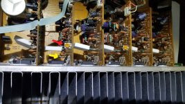
I've included some images, in the one image I have two arrows, the Red Arrow points to a trimmer that is on only found on the L / R channels amp boards. Judging from the type of wires running to these pcb's I'm assuming these pot/trimmers are a "line input levels" (for gain up or down). However I'm not sure how these circuits were designed, and more importantly what an over-current circuit looks like (and or where they would locate it) so these might also be the "cut off voltage trimmers?" I dunno hence why I am posting here.
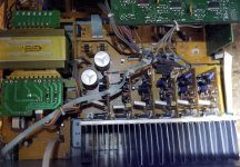
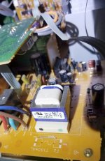
I've also included a potential "sectioned out pcb" that looks like it might be regulating the voltage... so perhaps this is the over current circuit?
But lastly, I also marked a "yellow arrow" to what I originally thought was temperature sensors doing the cut off....(it looks an awful like a Thermistor to me) AND the PCB label for this part is literally "TH731" further indicating it's "THermal" sensor, so perhaps I can just swap these out with another value? Or put a resistor in their place? But what value... hmmm.
Any help would be greatly appreciated!
I can tell whoever set this protection circuit up must have leaned towards safety over performance, because the heatsinks are not even hot.
I opened it up and I thought I saw "temperature sensors" thermistor's near the amp chips, with the "left channel" one being bent very close to the amp IC (I bent it back like the others) and I assumed ok now I'll get more volume. But I got the same cut out at around the exact same volume. So I installed a large PC fan on the heatsink to keep it cool... and it cut off at the same volume (I might add this is not digital/display volume on the unit - but the same audible volume).
So there is something causing the cut off to cut out long before it's technical abilities are overloaded/tapped.
I'd like to figure out where the over-current protection circuit might be, and possibly remove it and or change it's value so it does not cut out so soon before the peak performance of this unit has had a chance.
I might add some key points:
The speakers I am using are in A+B combination (4 speakers) / the unit states in the manual use only 8 or 16ohm speakers at each terminal, however both pairs of my speakers being used are 4ohms. Technically speaking I get away with using these same speakers on other receivers fine (making sure to always use a good fan to keep the heatsink cool) and there is no issue driving them hard for extended periods. I have one Sony 110w which only has Speaker A terminals and it's got a hard switch to select 4ohm or 8ohm, so I set it to 4ohm and installed the 2x 4ohm speakers totalling 2ohms and ran it for 10mins, the heatsink got so hot I panicked and installed a permanent fan. Now it runs fine 2ohm speakers testing for a solid hour at loud volume, no issues (and stays just warm now).
So out of all these other receivers I've run these same speakers off - this is the only unit having "issues" and I think it's simply because they set the cut off limit too low.
I've included some images, in the one image I have two arrows, the Red Arrow points to a trimmer that is on only found on the L / R channels amp boards. Judging from the type of wires running to these pcb's I'm assuming these pot/trimmers are a "line input levels" (for gain up or down). However I'm not sure how these circuits were designed, and more importantly what an over-current circuit looks like (and or where they would locate it) so these might also be the "cut off voltage trimmers?" I dunno hence why I am posting here.
I've also included a potential "sectioned out pcb" that looks like it might be regulating the voltage... so perhaps this is the over current circuit?
But lastly, I also marked a "yellow arrow" to what I originally thought was temperature sensors doing the cut off....(it looks an awful like a Thermistor to me) AND the PCB label for this part is literally "TH731" further indicating it's "THermal" sensor, so perhaps I can just swap these out with another value? Or put a resistor in their place? But what value... hmmm.
Any help would be greatly appreciated!
Attachments
Last edited:
")
