The Capacitance Multiplier
One of the simplest methods of regulation is just a plain capacitor. However, there comes a time when it's less expensive to use regulation - large capacitors can cost lots of money.
Someone once told me that a power supply was the exact same as as an amplifier, except you were trying to keep the output steady.
Look at this.
https://i198.photobucket.com/albums/aa290/keantoken/CapacitanceMultiplier.png
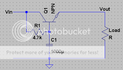
First, notice C1. This is a filtering cap. R1 supplies Q1 with enough base current to give the load power. Voltage fluctuations are filtered out by C1 so that Q1 has steady base current, and so the output voltage will be steady.
This simple circuit has a trick: the transistor has the effect of multiplying the capacitance of C1. So if the transistor has a gain of, say, 100, then we would have an effective capacitance of 100000uF, or 100mF! This is the basis of many simple regulator designs.
Now let's look more closely at what's happening. The transistor will keep the output voltage at about 0.6V below the input voltage, or more directly the voltage across C1. So if you have an input voltage of about 13.8V, your output would be about 13.2V
The downfall of this deign is that it will always have a voltage drop of 0.6V.
[my brain has stopped working, so I wouldn't mind if someone would expand upon the above principles and make them more comprehensive]