Feedback soundclip "Synergy-07x3fe22-10pb" Patricia Barber - A taste of honey.
Hope useable and put a gran of salt, we seldom express the perceived in same way and a recording plus distribution between us.
First i say sounds good when listening by itself without comparing. Compared to the same track on YouTube (to be clear not the kees52 amp clip) say I've listened other of your speaker builds as sound clips where it seems a tendency when it's a Trynergy, room is much less involved especially this clip. Your clip is much brighter have nearly a ringing up very high a guess 10kHz easy to hear when tambourine come in just before drummer. This makes the original YouTube clip much warmer and softer in hole sound picture and very easy reconized in the reverb that has more depth in orginal and yours is bit thin/bright reverb.

Synergy for TB & Sony drivers, PE buyout
Hi there X: Thanks for the simm(s), culminating in Post #158. Your are a helpful friend indeed. I'll try to figure out the foam core cutting plan from your previous posts. I will be byamping HF/Mid and have always expected to use a bass unit with 120hz(+-) xover, which is on target. ...regards, Michael
Hi there X: Thanks for the simm(s), culminating in Post #158. Your are a helpful friend indeed. I'll try to figure out the foam core cutting plan from your previous posts. I will be byamping HF/Mid and have always expected to use a bass unit with 120hz(+-) xover, which is on target. ...regards, Michael
Regarding the recording still think listened isolated sound good bright or not and especially when thinking the long path, first pro recorded, distributed to media, played back your basement and recorded homegear, then distributed to lover bitrate media, last played my homegear.
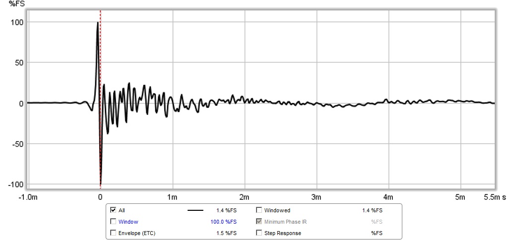
Don't laugh or just do but haven't got to the point yet where have experience REW and technical plots as IR, you know only last week got the UMM-6 microphone so will come, but in reality i need to read some manuals regarding IR. Have a feeling though it's that first 0,083mS down or upward ringing after the 100% ones.
Attachment is just my interest/curiousity or trying to help little, look 3FE22 8ohm datasheet frequency plot, could be that the 45º reading 12-15kHz upward boom, that when it passes through horn lens will be added more or less on axis.
Attachments

Hi there X: Thanks for the simm(s), culminating in Post #158. Your are a helpful friend indeed. I'll try to figure out the foam core cutting plan from your previous posts. I will be byamping HF/Mid and have always expected to use a bass unit with 120hz(+-) xover, which is on target. ...regards, Michael
Michael J Droke,
You are welcome - just hope you build it. Looking forward to seeing your progress.
I was wondering, X, could you make a PDF of the profile of the horn at the point where the sides meet the top/bottom panel?
I'm taking a different route in my construction (more on that if it works), and making a jig would be very useful!
This will take some work as that interface is defined in 3d and again has to be projected to 2d for a cut plan. I will see what I can do. I skipped it because I was in a hurry to build something and knew that the mechanical constraints could force the curve from a flexible panel. I guess you are cutting conventional layers and stacking?
Afcourse I need a amp for the tapped horn first.
This is a allfet amplifier and has very low impedance. Thus not
a hybrid, for max 100 Hz it is not needed, but go test this amp
with a wideband speaker to hear all sound from it.
almost ready with the PCB.
regards
kees
This is a allfet amplifier and has very low impedance. Thus not
a hybrid, for max 100 Hz it is not needed, but go test this amp
with a wideband speaker to hear all sound from it.
almost ready with the PCB.
regards
kees
Attachments

Kees,
Neat design there - what are the design's performance specs? There is an inductor - almost looks like a class D but you are an analog guy through and through so probably not.
You should post this in the solid state amp forum as it is a bit OT here. Very cool though. In the class D forum, one of the members just designed a new PCB for the TPA3116 as a group buy with all the options and the main difference being a PBTL monoblock capable of 100w into 2ohms. I bought a couple of boards and will have to populate them with SMT parts. The TPA3116 is what I use now and all the sound clips posted are played through it.
Hi kees52 looks nice, if you like spare time to put in your car and Trynergy builds, here link same princip amp regarding output devices though it use only one output pair but dual device into same package. 150 Wrms/8 Ohm 230 Wrms/4 Ohm plus other fine specs http://www.diyaudio.com/forums/vendors-bazaar/248996-first-one-mosfet-amplifier-module.html.
Kees,
Neat design there - what are the design's performance specs? There is an inductor - almost looks like a class D but you are an analog guy through and through so probably not.
You should post this in the solid state amp forum as it is a bit OT here. Very cool though. In the class D forum, one of the members just designed a new PCB for the TPA3116 as a group buy with all the options and the main difference being a PBTL monoblock capable of 100w into 2ohms. I bought a couple of boards and will have to populate them with SMT parts. The TPA3116 is what I use now and all the sound clips posted are played through it.
You are right, I do not like D, I have it elsware, it is in allfet threads, I have get my inspiration from there.
This momente I am busy with a loudspeaker jigg for measuring speakers, it constists of a 6 watts class b amp and some opamps, it will work a lot better with limp then through a pc headphone output.
And yes it is OT.
regards
kees
Hi kees52 looks nice, if you like spare time to put in your car and Trynergy builds, here link same princip amp regarding output devices though it use only one output pair but dual device into same package. 150 Wrms/8 Ohm 230 Wrms/4 Ohm plus other fine specs http://www.diyaudio.com/forums/vendors-bazaar/248996-first-one-mosfet-amplifier-module.html.
Looks like you have the same? I am happy that you use current feedback, it is the way to go to prevent feedback have impact on sound, current feedback is independent of bandwidh, it give a fast amp who go easely beyond Mhz.
I have ones build the alexander amp, dit fit it with a super emitor follower and ringemitters, and burr brown drive opamp in current mode, still have the schematic did sound fantastic for a bipolair amp.
But now back to the speakers, who I need first to test amps. If you search on my name you find amps threats here but are old because I am now learn speakers, that is needed as say't.
regards
kees
This will take some work as that interface is defined in 3d and again has to be projected to 2d for a cut plan. I will see what I can do. I skipped it because I was in a hurry to build something and knew that the mechanical constraints could force the curve from a flexible panel. I guess you are cutting conventional layers and stacking?
No, nothing that drastic
I'm making use of different materials that I had lying around, and a big holding the pieces in place would make things easier. I know extracting that kind of information is difficult, so don't worry!Cut/Glue plan for full scale top/bottom flat walls
Here is the full scale pdf for the top and bottom panel walls. Use the Tile print feature in Acrobat so that the throat is 2.80 inches wide for the 1.0x scale version and 2.00 in wide for the 0.7x scale Trynergy. Note that since it is drawn full scale (1:1) on A1 paper, only half the horn is shown. Mirror the othee half for a full drawing if you wish, or flip drawing upside down once thru with one half of the walls. Again, my experience has been that an additional scale factor of 95% is needed to print from Acrobat to a true full scale Tile print.
Here is the full scale pdf for the top and bottom panel walls. Use the Tile print feature in Acrobat so that the throat is 2.80 inches wide for the 1.0x scale version and 2.00 in wide for the 0.7x scale Trynergy. Note that since it is drawn full scale (1:1) on A1 paper, only half the horn is shown. Mirror the othee half for a full drawing if you wish, or flip drawing upside down once thru with one half of the walls. Again, my experience has been that an additional scale factor of 95% is needed to print from Acrobat to a true full scale Tile print.
Attachments
Last edited:
No, nothing that drastic
What is your mystery material? Are you 'cutting wood' (or foam in this case) yet as they say? Please post pics of your build progress if any.
There will be more questions as I left out a lot of details and finer points if you are not used to building in foam from scratch. I leave details like that out on purpose because there are many ways to craft a foam core speaker box. One of the coolest developments by another member was the trick for using a long strip that is creased and folded then glued to side panels for a Karlsonator speaker. I had been cutting out individual pieces as if they were wood previously. But it turns out the entire core of the speaker could be made from a single strip folded and bent many times saving a lot cutting and gluing.
When I make the stereo pair I will take more photos along the way to provide a build guide for those new to foam core craftsmanship.
Last edited:
Some build photos from earlier
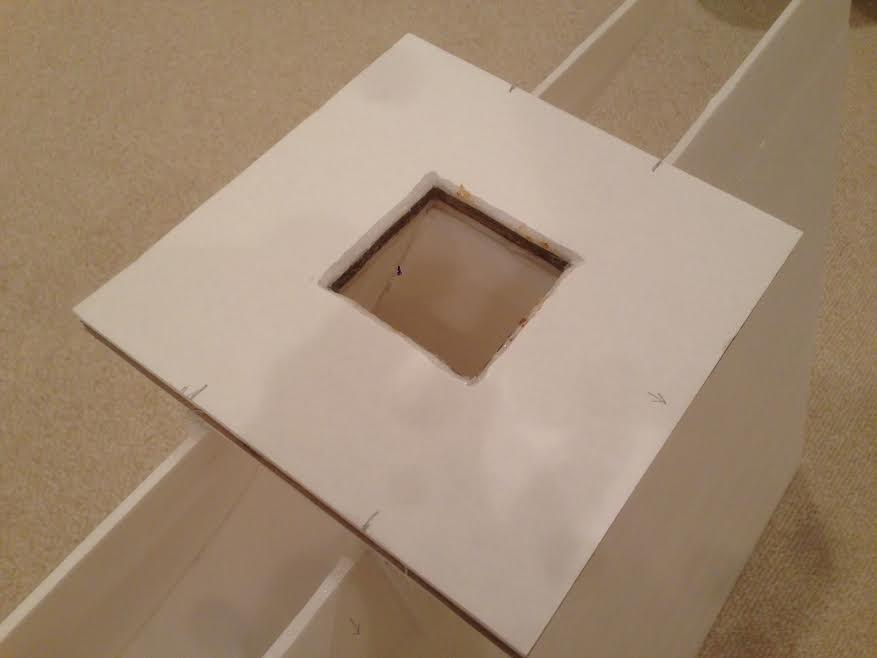
Just thought these might be useful for folks to see the interim stages of the build showing a closeup of the the throat flange where the driver bolts onto, and the rear chambers and how terminal binding posts are attached as well as how they are lined with foam.
Throat flange (note sandwich construction of FC-3-layer cardboard-FC):
Throat flange with 3FE22 installed and rear sealed chamber removed showing foam and polyfill damping material:
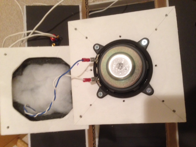
Rear view of Trynergy showing all three rear chambers in place:

Just thought these might be useful for folks to see the interim stages of the build showing a closeup of the the throat flange where the driver bolts onto, and the rear chambers and how terminal binding posts are attached as well as how they are lined with foam.
Throat flange (note sandwich construction of FC-3-layer cardboard-FC):
Throat flange with 3FE22 installed and rear sealed chamber removed showing foam and polyfill damping material:
Rear view of Trynergy showing all three rear chambers in place:
Attachments


Last edited:
Ok, you've twisted my arm Oh, and it seems to be working, so it might be worth showing...
Ages ago I wanted to build the cornu spiral speakers that Cal Weldon and xrk971 had designed. I was struggling with Foam Core board, so I looked for a material that was flexible in one dimension, but stiff in the other.
Whilst walking around Lowe's one day, I came to the section where they sell damaged display items. Lo and behold there were a number of sheets of plastic that are used in lighting fixtures (the thin sheet that sits on a flange in the soffit, making the light from fluorescent tubes more diffuse).
Brand-new, these sheets were nearly $10 a piece, but the damaged ones (where a corner had been snapped off) sold for 10 cents! So began my escapade
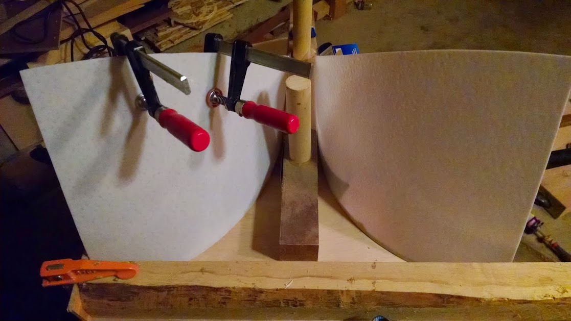
Now, I'm using those sheets as the curved walls in the Trynergy. The plastic cut really nicely with my bandsaw, and I had some squares of 3/8" plywood left over from the abandoned Cornu project. So, I used construction glue to attach the plastic panels to the plywood sheet.
I did it in stages, gluing up the throat. Once that had set, I used small clamps as weights to hold the panels in the correct curve while the remainder of the glue line was setting.
I hope the pictures make sense! The first one was more time consuming, as the second one was approached with the jig that I'll eventually make from X's template in mind. Using a wooden tab I was able to locate the end of the mouth into the corner of it and a larger block, and using the small clamps again I was able to get the curve correct and glued up in one step.
I hope these pictures make sense!
Gluing up the first side, step two of three:

Step three of three:

Gluing up the second side, step two of two:

A general shot looking at the mouth. Note that the smooth side of the panel is facing us, so the texture is on the back. I didn't want to mess with any high frequencies!
I'm sure there will be bracing to do, and I'll have to think about where to cut the synergy ports, but I'm alright with the project running at this pace. I rarely get eight hours to work on something like this in one go!
Oh, and it seems to be working, so it might be worth showing...Ages ago I wanted to build the cornu spiral speakers that Cal Weldon and xrk971 had designed. I was struggling with Foam Core board, so I looked for a material that was flexible in one dimension, but stiff in the other.
Whilst walking around Lowe's one day, I came to the section where they sell damaged display items. Lo and behold there were a number of sheets of plastic that are used in lighting fixtures (the thin sheet that sits on a flange in the soffit, making the light from fluorescent tubes more diffuse).
Brand-new, these sheets were nearly $10 a piece, but the damaged ones (where a corner had been snapped off) sold for 10 cents! So began my escapade
Now, I'm using those sheets as the curved walls in the Trynergy. The plastic cut really nicely with my bandsaw, and I had some squares of 3/8" plywood left over from the abandoned Cornu project. So, I used construction glue to attach the plastic panels to the plywood sheet.
I did it in stages, gluing up the throat. Once that had set, I used small clamps as weights to hold the panels in the correct curve while the remainder of the glue line was setting.
I hope the pictures make sense! The first one was more time consuming, as the second one was approached with the jig that I'll eventually make from X's template in mind. Using a wooden tab I was able to locate the end of the mouth into the corner of it and a larger block, and using the small clamps again I was able to get the curve correct and glued up in one step.
I hope these pictures make sense!
Gluing up the first side, step two of three:
Step three of three:
Gluing up the second side, step two of two:
A general shot looking at the mouth. Note that the smooth side of the panel is facing us, so the texture is on the back. I didn't want to mess with any high frequencies!
I'm sure there will be bracing to do, and I'll have to think about where to cut the synergy ports, but I'm alright with the project running at this pace. I rarely get eight hours to work on something like this in one go!
unaHM,
Nicely done! Wow - fluorescent lamp diffusers as speaker material never would have thought of that one. Great progress and love your use of alternative materials. You will probably need to do the CLD on the plastic as it will vibrate like a drumhead. Too bad too as it would have been cool to have lights on the outside walls illuminating the horn channel.
 Bravo!
Nicely done! Wow - fluorescent lamp diffusers as speaker material
never would have thought of that one. Great progress and love your use of alternative materials. You will probably need to do the CLD on the plastic as it will vibrate like a drumhead. Too bad too as it would have been cool to have lights on the outside walls illuminating the horn channel. Bravo!- Home
- Loudspeakers
- Multi-Way
- Presenting the Trynergy - a full range tractrix synergy.