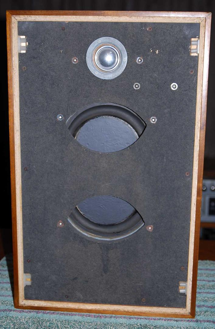
If you have a look at the Kef Concord from the late 1960s, the B139 seems to be half hidden behind the baffle board:
Why would Kef do this?
What effect would it have on the sound output?
I am not really interested in the qualities of the speaker as a whole, I am aware that the B139 is only effective up to about 800Hz and that the T15 isn't really likely to cope adequately above that. I just can't understand the logic behind hiding half of the bass driver; particularly since in relation to this speaker, Kef say
Kef LINKMany otherwise fine loudspeakers at the time were ruined by their grille fabrics, which upset the frequency response ...
Some sort of an attempt at using the baffle board as a phase plug to correct for frequency peaks or droops? According to this link audio-talk :: View topic - Kef Concord loudspeakers. "The Concord had B139 XOed to T15 at 1kHz, The B139 has a nasty resonance right near there and even using it as high as 400 Hz is pushing it. To get the tweeter to go that low its extension is not all that good. "
Factory data sheet here. TL Links
Factory data sheet here. TL Links
Apart from what surv1v0r noted, i think there "might" be other reasons, and/or too.
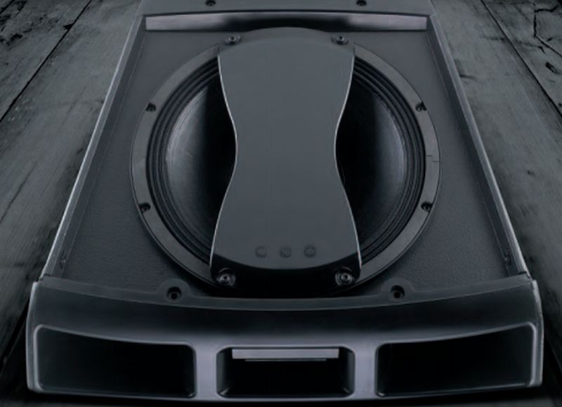
1 - That device appears similar to what's used in some Pro line arrays.
2 - Richard Small of Thiele/Small fame, in one of his papers stated that, obstructions can either increase/decrease output, depending on type.
So a couple more ideas to consider 😉
If anybody knows exactly why KEF did that, i'm sure we'ld like to know 🙂
More from Nexo:
"In line arrays, the physical diameter of cone drivers would appear to make it impossible to achieve interference-free, close coupling of wavesources at the frequencies necessary to crossover with HF drivers. NEXO’s revolutionary Directivity Phase Device causes an 8 inch driver, for instance, to behave as twin 4 inch drivers, with two acoustical centres spaced 5 inches apart, cleverly extending the upper frequency limit for line source coupling between adjacent woofers."
"In line arrays, the physical diameter of cone drivers would appear to make it impossible to achieve interference-free, close coupling of wavesources at the frequencies necessary to crossover with HF drivers. NEXO’s revolutionary Directivity Phase Device causes an 8 inch driver, for instance, to behave as twin 4 inch drivers, with two acoustical centres spaced 5 inches apart, cleverly extending the upper frequency limit for line source coupling between adjacent woofers."
Possible that in the Kef baffle, the twin eyeshaped openings create two new acousstic centers, then facilitate the crossover add on point to the tweeter? , it is , one B139 becomes = two B110's ?
I must admit that that had crossed my mind but as you perhaps suggest, why waste half of a B139 when it would seem much more logical to use all of two B110s?Possible that in the Kef baffle, the twin eyeshaped openings create two new acousstic centers, then facilitate the crossover add on point to the tweeter? , it is , one B139 becomes = two B110's ?
I must admit that that had crossed my mind but as you perhaps suggest, why waste half of a B139 when it would seem much more logical to use all of two B110s?
When you mask off the diaphragm it doesn't 'waste' any of the speaker. Output is determined by displacement*, and displacement doesn't change when you mask off the cone of a driver. So you basically get the output of an eight, with the directivity of a couple of fives.
* exception to this rule would be when you're limited by power handling. But generally one eight will have power handling which is comparable to a couple of fives, unless the voice coil on the eight isn't any bigger than on the fives.
In those days voice coil overhang was proportional to cone area. Maybe they were loading the driver to lower Fb?
Hi,
FYI: IME (40 Years ago) If detaching the restrictive covering on the Driver front-side: Frequencies around ~1 kHz did not sound as good as when mounted. The Speaker acted like an T-W-W system with halving the C-C distance between the Drivers for a much better XO summing than if no area splitting is in use.
I used those speakers placed horizontally(One of KEF:s recommendations) with the tweeters at the inside of a ~isosceles triangle.
The sweet-spot could accommodate 2 listeners at most with unsurpassed phantom focus if compared to a vertical set-up. My room at that time was very absorptive and walls acting very diffusing on reflexes.
b 🙂
Attachments

Some sort of an attempt at using the baffle board as a phase plug to correct for frequency peaks or droops? According to this link audio-talk :: View topic - Kef Concord loudspeakers. "The Concord had B139 XOed to T15 at 1kHz, The B139 has a nasty resonance right near there and even using it as high as 400 Hz is pushing it. To get the tweeter to go that low its extension is not all that good. "
Factory data sheet here. TL Links
I think thats right. The styrofoam diaphragm was known to have some serious modes fairly low down. The aluminum foil skin was a partial fix as first used by Barlow in the Leak woofer.
No different than a lot of tweeters where the first big vibrational mode can be reduced in effect with the right phase plug, forcing some sound portions from part of the diaphragm to go extra distance to offset how it is out of phase. Most likely there is a big beam mode with the center out of phase with the two ends.
http://p10hifi.net/TLS/drivers/images/B139B_newer.gif
Response curve here. Note the peak at 700 and the dip at 1800, leading to difficulty when used in a 2 way.
David S
I am way out of my depth here but I can't really get to grips with that. Surely the displacement must be unobstructed? Otherwise, why not simply block off the entire driver to protect it from tiny inquisitive fingers. I realise that this is taking it a bit far but at the very least, some of the displaced air will bounce back off the obstruction and interfere with the movement of the diaphragm?When you mask off the diaphragm it doesn't 'waste' any of the speaker. Output is determined by displacement*, and displacement doesn't change when you mask off the cone of a driver. [TEXT SNIPPED]
ps - interesting graphs speaker dave, thanks for that. Were Kef suggesting that the effective usable frequency range of the B139 is 25Hz to 500Hz? Do you by any chance have similar data for the B110 & T27?
Last edited:
Damage limited excursion 12mm p>p...times have changed. I just assisted my prosound buddy set up his new small rig with 4 LAB 12 tapped horns. It does seem like our time is about realizing what the Brits of the mid 20th imagined decades ago.
On the Spendor BC111 there is a deliberate restriction of the woofer opening on the front baffle. This was the bigger brother of the BC1 and had similar BBC origins. It was a 4 way (the BBC version was only a THREE way) system with the 12" bextrene bass unit crossing over to an 8" mid' at about 400 c/s. They are a vertically aligned layout and the bass unit has two strips down each side which form a vertical opening about 9" wide and 12" high. There is currently a nice photo of one on Australian eBay, posted 22nd June at 14:05 hrs. (Go electronics> audio> "speakers and sub woofers" section.) In this case the designer stated quite clearly that in this case they were placed there to narrow the aperture from which the bass frequencies emerged so as to increase horizontal dispersion and reduce "beaming" in that region. I.e. near the bass/mid cross over point. It was all written up in a three part article in "Wireless World" circa 1968? (And I think the author of those articles was Dudley Harwood of BBC Research and not Spencer Hughes of Spendor.) I am guessing that this is NOT exactly the same rationale as the Concord but can't be certain especially given the comment in an earlier post about using them lying on the long axis rather than the vertical.
Cheers from Oz. Jonathan
Cheers from Oz. Jonathan
Last edited:
SpeakerDave has it right. It is a phase plug to control the effects of cone breakup just as is done with rigid diaphragm tweeters. This allows the B139 to be used up to higher frequencies to cross over to the T15 directly rather than need a B110 as a midrange.
Not really a good solution: Both drivers are being used over a wider frequency range than is optimum. There will be consequences on distortion, coloration, directivity etc, but it is cheaper than a 3-way!
The idea that you can split a single large driver with a central baffle and make it appear as though it is two smaller drivers with a common acoustic center with the directivity of a smaller driver is pure hokum. Spaced drivers absolutely behave as spaced drivers, not as a common single driver. Just look at the impulse response off axis and you will see two non-coincident impulses. Its why center channel speakers behave so badly horizontally off axis!!
Andrew
So, an unsuccessful attempt at a cost-cutting compromise then?
I presume that that is why Kef never repeated the exercise and the technique is not more common.
I also get the feeling that the T15 was not deemed to be a successful driver, is that correct?
I presume that that is why Kef never repeated the exercise and the technique is not more common.
I also get the feeling that the T15 was not deemed to be a successful driver, is that correct?
The T15 is interesting. The dome is similar to the much later T52 found on the early R105's and other KEF combinations from the 70's (R103?). If you remove the metal ring from the T15 held on with three Philips head screws you get an almost identical looking driver to the T52. The T52 was a very well regarded driver in its day one of the very few to come out of the "HiFi Choice" group tests without a criticism. But I understand the voice coil is different from the T15 with greater power handling. I have never seen a T52 used under 2,500 c/s while the T15 has been used from around 1,000 c/s i.e. on the Concord.
It was successful enough that we are writing about it 😉.So, an unsuccessful attempt at a cost-cutting compromise then?
I presume that that is why Kef never repeated the exercise and the technique is not more common.
The "eye" holes are an acoustical band pass, to correct the woofer's peaking response above 1000 Hz would have required a lot of crossover parts, and still may not have been as effective.
Using the faceplate as an acoustical band pass cut the LF crossover parts count to one coil.
Looks like they got about the best possible results without adding the expense of going three-way.
Attachments

Re: #17. There is a guy called Royle over on the dedicated vintage KEF site who would be the best person to follow this (KEF tweeters) up with. Google "hifiloudspeakers" and it should pop up. They have a forum.
Cheers Jonathan
Cheers Jonathan
- Status
- Not open for further replies.
- Home
- Loudspeakers
- Multi-Way
- What is the effect of hiding the B139 in the Kef Concord?