Welcome aboard JG ! It will be great that you are doing this as your 3d cad work is top notch and you are fast. 🙂
Would you consider 3d printing this?
Thanks for the rice measurement of the cone volume. Looks like a cone filler plug will be needed. I will show what it looks like without one.
It will be really helpful that you are on board because until we lay it all out on a 3d model it will be tough to see if this horn is physically buildable. I have some concerns with how small the panels are relative to the size of the drivers that need to mount to them. I think we may be looking at mounting all 4 on the top and bottom panels and routing the injection ducts to the corners of the horn walls as long slot shaped ports. This may mean the port will be longer than the thickness of the wall. Not a big deal, but it has an effect on the bandwidth and needs to be modeled.
Let me hand draw a sketch of what I think this may look like with some dimensions of the design this far.
Last edited:
Initial plans for 55Hz or 100Hz Synergy Tripp 10in
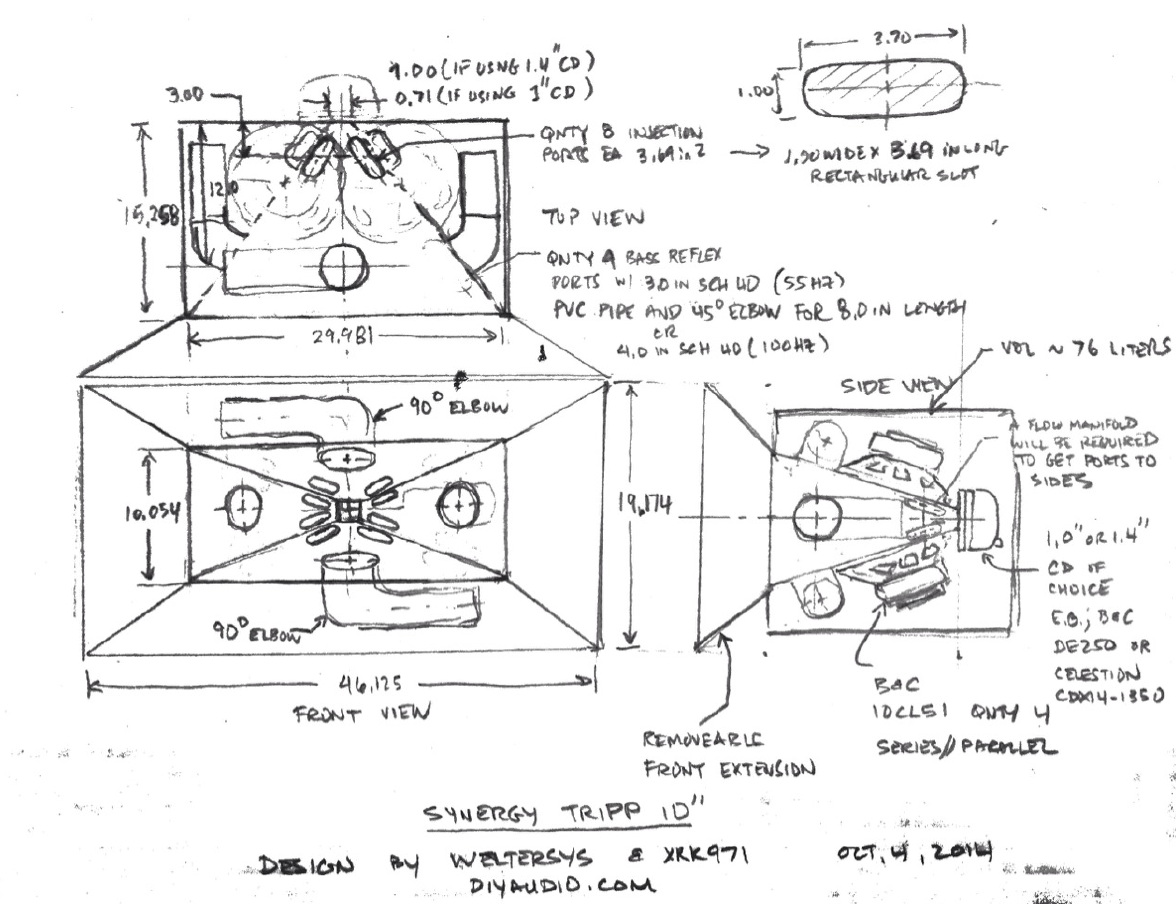
Based on the simulations thus far and on the Bwaslo spreadsheet from post #9, I came up with a rough plan that shows the essential concept and layout of ports and vents with a suggested driver mounting scheme. Hopefully, Jennygirl can take this and translate it to a nice CAD model.
I was going to make the bass reflex ports rectangular slots in the corners but that is probably a pain and not necessary given that the effects of the wall on the HF dispersion is not as important near the mouth. It is much simpler to go with qnty 4 x SCH 40 PVC elbows and pipe to achieve either 55Hz tuning (3 in pipe) or 100Hz tuning (4 in pipe), all 8.0 inches long.
For the main woofer driver injection ports, they are relatively close to the critical HF CD region and thus care has to be taken to minimize their impact on the wall surfaces. Thus keep them near the corners and use something like a 1.0 in wide x 3.70 in long slot with rounded ends. Some clever duct work and manifolding will be needed to get the flow from the top/bottom mounted drivers to get to the two side wall injector spots. There isn't enough room to mount drivers on the sides - at least I don't think so.
Note that a volume plug form will need to be placed inside the cone cavity to reduce it from 850 cc to about 450 cc in order to extend the bandwidth of the woofer higher to successfully XO with the CD at circa 700Hz to 900Hz.
Attachments

One question I have is with the un-phase plug used to take up volume under the 10CL51 cones. Without it, the high frequency cut off is too low. The throat port has to go through both the wall of the horn and the plug and gets to be over an inch long. Its length affects the rolloff as well as a has a big impact approaching the reflection null.
Do you anticipate any shaping of the surface of the plug closest to the dust cap to optimize the response?
Do you anticipate any shaping of the surface of the plug closest to the dust cap to optimize the response?
I was thinking the plug would be the inverse shape of the cone and dust cap with enough clearance for cone movement. A section would be cutout to allow flow access to the ports. I was thinking of shaping it with modeling clay that is hardenable. JG can just print it in 3d. Or pour one into the cone itself lined with plastic wrap using plaster of Paris or polyester resin.
Its that "section cutout to allow flow access to the ports" that I was asking about. Love to see what it looks like when its done.
Starting with plaster of Paris molded right in the cone is a good idea for the trial and error that is going to be needed!
Starting with plaster of Paris molded right in the cone is a good idea for the trial and error that is going to be needed!
I'll get started on the CAD file right away.
I think I understand everything, but I'll let you know if I hit any snafus.
Cheers!
I think I understand everything, but I'll let you know if I hit any snafus.
Cheers!
Wouldn't the synergy work better with the bass reflex ports to the sides? I remember reading a remark from Tom about his choice of placement of the ports to the side...
What material thickness(es) do you want to use?
Weltersys was going to use 1/2 in ply or 0.469 in thick as I assumed. Seems like a lot of SPL and maybe 3/4in (0.712in) may be better?
Last edited:
here is how it is coming, just getting stuff roughed out with curves before adding material thickness
the throat injection ports are kind of large, and as specific must be pulled away from the throat to fit the sidewalls of the horn
as well it doesn't look like there is much space to keep the BR ports completely inside the specified master chamber (unless it can exceed the dimensions of the main horn section like the right side view in your drawing)

This is with 4" reflex ports, figured I would do biggest specified dimensions first
the throat injection ports are kind of large, and as specific must be pulled away from the throat to fit the sidewalls of the horn
as well it doesn't look like there is much space to keep the BR ports completely inside the specified master chamber (unless it can exceed the dimensions of the main horn section like the right side view in your drawing)
This is with 4" reflex ports, figured I would do biggest specified dimensions first
Last edited:
Wouldn't the synergy work better with the bass reflex ports to the sides? I remember reading a remark from Tom about his choice of placement of the ports to the side...
You mean to the side as in not inside the horn? He uses 3 ways and there would be too many ports to put inside. This is a 2 way and has room for ports inside. I don't know of there is anything detrimental - maybe someone with synergy experience can chime in.
here is how it is coming, just getting stuff roughed out with curves before adding material thickness
the throat injection ports are kind of large, and as specific must be pulled away from the throat to fit the sidewalls of the horn
as well it doesn't look like there is much space to keep the BR ports completely inside the specified master chamber (unless it can exceed the dimensions of the main horn section like the right side view in your drawing)
This is with 4" reflex ports, figured I would do biggest specified dimensions first
JG,
Great questions - exactly what I was hoping we could go through to flesh this out. Just can't tell if it will fit until drawn to scale.
Let's try making the port slots 0.75in wide x equivalent length to keep CSA the same. The bass reflex vents look fine and if we use elbows I think it should fit.
Looks great.
Thanks,
X
Okay, went ahead and did a rough *inner* surface model of the 4" pvc corners.
throat injection ports have been resized to .75" diameter x 4.807" length to match CSA (total 3.485 sq in) and scooted in closer


Note: this is just an outer surface model, does not account for 0.5" material thickness
PVC fittings are 1.5" length near port exit, then 3.14" for 90 degree bend or 1.57" for 45, and leftover tube length added to equal 8" total
throat injection ports have been resized to .75" diameter x 4.807" length to match CSA (total 3.485 sq in) and scooted in closer
Note: this is just an outer surface model, does not account for 0.5" material thickness
PVC fittings are 1.5" length near port exit, then 3.14" for 90 degree bend or 1.57" for 45, and leftover tube length added to equal 8" total
Last edited:
You mean to the side as in not inside the horn? He uses 3 ways and there would be too many ports to put inside. This is a 2 way and has room for ports inside. I don't know of there is anything detrimental - maybe someone with synergy experience can chime in.
No, in the corners, where Weltersys had them in his original drawing...
I think it was discussed in that midrange for synergy thread.
JG,
You are GOOD! This looks great 🙂 I can really see how cool this is going to look and can imagine it will sound just as good as it looks.
Thanks!
X
You are GOOD! This looks great 🙂 I can really see how cool this is going to look and can imagine it will sound just as good as it looks.
Thanks!
X
You mean to the side as in not inside the horn? He uses 3 ways and there would be too many ports to put inside. This is a 2 way and has room for ports inside. I don't know of there is anything detrimental - maybe someone with synergy experience can chime in.
If I were building a compact version (minus the L45 horn extension), would it then make sense to do slot ports along the outer left and right edges? This would eliminate the need for PVC fittings and resulting bigger exterior box
JG,
You are GOOD! This looks great 🙂 I can really see how cool this is going to look and can imagine it will sound just as good as it looks.
Thanks!
X
Thanks xrk! 😀 I agree, it is looking awesome!
No, in the corners, where Weltersys had them in his original drawing...
I think it was discussed in that midrange for synergy thread.
I originally drew it that way but to keep things simple decided to go with 4 round PVC ducts instead of smaller oblong ducts on the corners. My experience with the Trynergy has shown me that when you are this close to the mouth it doesn't matter much. It is important when close to the throat but wven that has been questioned by how well the simple 11cm dia hole right next to the throat seems to work in his synergy. I am not too worried about it and thought keeping the bass reflex ducts simple with easy to buy and cut PVC pipe would be more user friendly. Although folks are free to go the complicated 8 duct route.
Last edited:
If I were building a compact version (minus the L45 horn extension), would it then make sense to do slot ports along the outer left and right edges? This would eliminate the need for PVC fittings and resulting bigger exterior box
I agree and was thinking the same thing. A slot port will require a bit of cutting wood and I would have to redo the sims to estimate the CSA and length as there is more surface drag on a slot port and it is treated differently in AkAbak.
I agree and was thinking the same thing. A slot port will require a bit of cutting wood and I would have to redo the sims to estimate the CSA and length as there is more surface drag on a slot port and it is treated differently in AkAbak.
Okay neat, I was just wondering. I am down with finishing this one first and then moving on to the compact version
- Status
- Not open for further replies.
- Home
- Loudspeakers
- Multi-Way
- Synergy Tripp 10"