After auditioning Gary Eickmeier's new IMP's last week along with the behringer B2031A's, I was impressed with both systems. They each had their own great strengths. The behringer's for their focused detail and the IMP's for their spaciousness.
However, they had one thing in common....
Poor stereo center image localization.
Also, Gary's system had "larger than should be" imaging, and the berhringer's had the problem of being omni-polar at frequencies below the baffle step and mono-polar for frequencies above, which gave a disconnected sound because there were reflections for lower frequencies and no reflections for high frequencies.
So, I started thinking about ambiophonics (I know, when am I not) haha.
I was just about to build a reference ambiopole before the experience with the IMP's and the B2031A's.
And to tell you the truth, it's annoying keeping your head still during listening.
Also, only 1 person can enjoy it at a time.
So I've been racking my brains so much lately on how to get the best of all worlds. Ya know.....(forgetting that I already washed my hair in the shower kind of obsessing) LOL
Now, this is what I've come up with.

This is an exploded view from the top.
It has 3 sides, 3 waveguides, 3x12 vifa tc9's
It will have active matrix wiring.
The front has L&R summed to mono, rear left is L, rear right is R
They will all have their own volume control.
The rectangles inside just show the depth of the waveguide plus CD tweeter.
This project borrows heavily from Elias' thread, http://www.diyaudio.com/forums/multi-way/200040-stereophonic-sound-single-loudspeaker.html
The difference is that I am using waveguides for controlled dispersion.
also, these will not fire to the sides, but rather to the rear at a 60 degree angle.
There are two reasons for this.
1. Not all of us have symmetrically rectangle rooms.
2. The plots I have seen for this and most waveguides, show that at 60 degrees, amplitude is down by 6 db, and as we know from LR style crossovers, -6 db x 2 will give a flat response.
So, i'm anticipating a pretty flat response as you move around the speaker.
I ordered the parts today, I already have the B/BB grade Baltic birch.
I'll be ready to start next week.
Forgot to mention, I'm using the mini-dsp of course.
Any feedback is welcome
Wish me luck!
However, they had one thing in common....
Poor stereo center image localization.
Also, Gary's system had "larger than should be" imaging, and the berhringer's had the problem of being omni-polar at frequencies below the baffle step and mono-polar for frequencies above, which gave a disconnected sound because there were reflections for lower frequencies and no reflections for high frequencies.
So, I started thinking about ambiophonics (I know, when am I not) haha.
I was just about to build a reference ambiopole before the experience with the IMP's and the B2031A's.
And to tell you the truth, it's annoying keeping your head still during listening.
Also, only 1 person can enjoy it at a time.
So I've been racking my brains so much lately on how to get the best of all worlds. Ya know.....(forgetting that I already washed my hair in the shower kind of obsessing) LOL
Now, this is what I've come up with.

This is an exploded view from the top.
It has 3 sides, 3 waveguides, 3x12 vifa tc9's
It will have active matrix wiring.
The front has L&R summed to mono, rear left is L, rear right is R
They will all have their own volume control.
The rectangles inside just show the depth of the waveguide plus CD tweeter.
This project borrows heavily from Elias' thread, http://www.diyaudio.com/forums/multi-way/200040-stereophonic-sound-single-loudspeaker.html
The difference is that I am using waveguides for controlled dispersion.
also, these will not fire to the sides, but rather to the rear at a 60 degree angle.
There are two reasons for this.
1. Not all of us have symmetrically rectangle rooms.
2. The plots I have seen for this and most waveguides, show that at 60 degrees, amplitude is down by 6 db, and as we know from LR style crossovers, -6 db x 2 will give a flat response.
So, i'm anticipating a pretty flat response as you move around the speaker.
I ordered the parts today, I already have the B/BB grade Baltic birch.
I'll be ready to start next week.

Forgot to mention, I'm using the mini-dsp of course.
Any feedback is welcome
Wish me luck!
Last edited:
Very cool and as usual, way over the top on TC9FD driver count! 
I am still unclear of the arrangement of Vifa's relative to the waveguides. Your drawing is a top view but that would mean it aims up? Or is it the waveguide and 12 Vifa's have been rotated 90 up so we can see the arrangement? What freq will the XO be or you may get a weird circular comb filter effect.
Very cool though - looking forward to seeing the final build. It is only 1 box right?
I implemented Elias' circuit in a three driver tc9fd with sides firing at 45 deg and very much like the presentation in a smaller office. I do get stereo with a single speaker.
Hey xrk, how ya been.Very cool and as usual, way over the top on TC9FD driver count!
I am still unclear of the arrangement of Vifa's relative to the waveguides. Your drawing is a top view but that would mean it aims up? Or is it the waveguide and 12 Vifa's have been rotated 90 up so we can see the arrangement? What freq will the XO be or you may get a weird circular comb filter effect.
Very cool though - looking forward to seeing the final build. It is only 1 box right?
I implemented Elias' circuit in a three driver tc9fd with sides firing at 45 deg and very much like the presentation in a smaller office. I do get stereo with a single speaker.
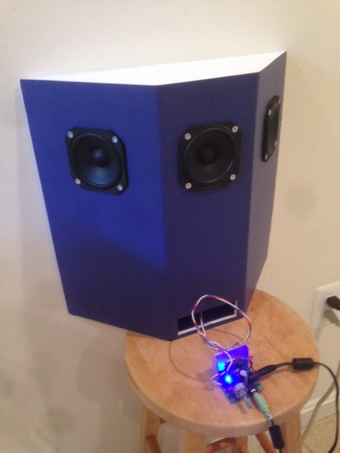
This is an exploded view.
Thos are the three sides.
Yes I have the tc9's around the waveguide.
Crossover will be steep at 1khz, so the circle arangement will be 1 wavelength apart (13.5")
I chose this way instead of a 12" driver under the waveguide, which will create 1 bad vertical lobe.
The vifa's will be omni at that frequency..... I realize they will sum but we will see how it goes.
Also, those frequencies will get in the waveguide (maybe adding to directivity?)
Anyway, vertical polars are aweful with traditional waveguide on top of larger driver speakers.
This is a little experiment with the driver arangement, so we'll see how it goes.
Yeah it's only one box.
Not after you put them in a ring like that.The vifa's will be omni at that frequency
This seems like potentially a big problem to me, but I dunno, maybe not.Also, those frequencies will get in the waveguide (maybe adding to directivity?)
Pretty sure your null spacing vs. crossover point situation here should be very much like a lot of those designs, except on every axis? You're in MTM arrangement here, remember. If you can actually match the -6dB of the MTM nulls at xover to the waveguide's 75°, that might be pretty cool, but I thinnnnk you're gonna have a gap here between where that happens and where the waveguide has directivity control.Anyway, vertical polars are aweful with traditional waveguide on top of larger driver speakers.
Sure, do a panel, measure it. Sounds interesting enough to me, and if it doesn't work, there's no shortage of cool things to try with all those drivers.This is a little experiment with the driver arangement, so we'll see how it goes.
Last edited:
You were the one that inspired me to buy a MiniAmbio and I love it.
I think that once you get used to Ambio, a lot of systems seem to have a 'hole' in the middle of the soundstage.
One idea I've had is to have a dipole ambiopole, with the rear drivers aimed at 45 degrees.
Here's why this might work:
Ambio has a really strong center image. But I find that recordings don't have width and depth unless they're really well recorded. In other words, when I listen to 95% of my music, it nearly sounds mono on an ambiopole.
This isn't an ambio problem; it's a recording problem. Basically ambio is faithfully representing the recording, and the recording is (close) to mono. A lot of my music is like this.
By making the speaker a dipole, we get a strong reflection off of the back wall, and that creates some pleasant additional width and depth.
You could create the same effect with Gary's Imps by simply moving them very close together, and plugging a MiniAmbio into the chain.
Also, I find that Ambio is INSANELY sensitive to timing problems. Due to that, I would personally discourage you from using a waveguide, unless it's a Synergy horn. In my listening tests, I found that the best Ambio speakers are the ones that don't have any timing issues.
Basically Ambio works better when the phase response is correct. It's hard to achieve that with a two way with waveguides, because the CTC spacing is so high. Synergy horns works well, and so do full range drivers.
If you don't want to use a full range speaker or a Synergy Horn, go buy some Kef coaxes. They're readily available for under $100 on eBay.
I'd like to see more but here the photo isn't showing. Just a graphic which says the Photobucket file has been moved.
Sorry, the mobile version of photobucket is a PITA sometimes.
The images are back up.
Sorry, the mobile version of photobucket is a PITA sometimes.
The images are back up.
Have you heard the Gradient Revolution?
From the diagram, it looks like your speaker will look similar:
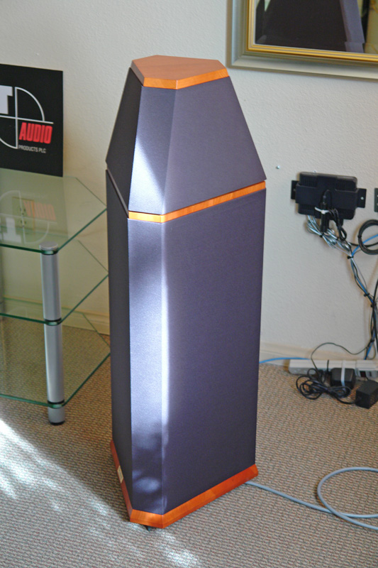
The Gradient uses a Seas Coax, whereas yours is a Vifa/Waveguide coax
Oh wow!
That looks very similar.
Mine will be only one speaker in the middle.
I thought about using the kef coaxes but they didn't have enough controled dispersion.
(it's only a 5.5" driver)
Thanks for the compliment about me getting you into ambio by the way.
Glad it works for you
That looks very similar.
Mine will be only one speaker in the middle.
I thought about using the kef coaxes but they didn't have enough controled dispersion.
(it's only a 5.5" driver)
Thanks for the compliment about me getting you into ambio by the way.
Glad it works for you
xrk, give me your impressions on this bad boy.
I was always weary of Elias' speaker.
It seams you have pointed the L & R drivers out by 45 deg.
Where as his fire directly to the sides.
xrk, give me your impressions on this bad boy.
I was always weary of Elias' speaker.
It seams you have pointed the L & R drivers out by 45 deg.
Where as his fire directly to the sides.
I pointed it 45 deg because I wanted to use it flush against a wall in my office. The 45 deg is used by Nagaoka matrixed stereo. The matrix circuit I used is the Elias circuit with the psychoacoustic filter that serves to reduce HF content on the middle driver. It produces a decent stereo effect - not as good as two separate speakers IMO and depends on having side walls. It is very dramatic when you pan the stereo image left to right and nice versa. You can really hear it even though it emanates from one box. The TC9FD's work very well for this in full range. With single driver the polar dispersion is pretty good. Your WG approach may be better. Looking forward to seeing how your concept works.
You know, your speaker arrangement can be modeled in AkAbak - 12 drivers encircling a waveguide. Is the profile on your WG published ? Or maybe you can measure it.
Yeah, it's the dayton 10" 90 degree waveguide.
I dont care to model the radiation pattern in software because I'm going to build it anyway.
I like to do things the hard way.... Lol
Well, your implementation is interesting.
Is there a thread on it?
I do worry about the off axis top end wonkiness of using a FR driver but i guess it can't be too bad at 45 degrees.
The Elias thread that started it is here: http://www.diyaudio.com/forums/full-range/257110-master-nagaoka-tetsuo-explorations-matrixed-single-stereo-speakers.html
The build is in this thread: http://www.diyaudio.com/forums/full-range/223313-foam-core-board-speaker-enclosures-239.html#post3961261
The model is here: http://www.diyaudio.com/forums/full-range/257110-master-nagaoka-tetsuo-explorations-matrixed-single-stereo-speakers-7.html#post3962898
The build is in this thread: http://www.diyaudio.com/forums/full-range/223313-foam-core-board-speaker-enclosures-239.html#post3961261
The model is here: http://www.diyaudio.com/forums/full-range/257110-master-nagaoka-tetsuo-explorations-matrixed-single-stereo-speakers-7.html#post3962898
The diagram in post#1 reminds me of the fig 8 in this patent:
Patent US8284976 - Sound reproduction with improved performance characteristics - Google Patents
Like others, I'm also looking forward to see how it goes. Must be very interesting.
Patent US8284976 - Sound reproduction with improved performance characteristics - Google Patents
Like others, I'm also looking forward to see how it goes. Must be very interesting.
The diagram in post#1 reminds me of the fig 8 in this patent:
Patent US8284976 - Sound reproduction with improved performance characteristics - Google Patents
Like others, I'm also looking forward to see how it goes. Must be very interesting.
I can't wait to see how it goes either, although I am worried about the driver arrangement around the waveguide and any lobing problems.
But traditionally with a waveguide on top of a large driver..... CTC spacing is nearly 2 wavelengths at the crossover.
With this, arrangement, it is 1 wavelength between the opposing driver.
I will have to fiddle with he crossover and see if i can get the lobe to produce that null at 60 degrees, then the arrangement will actually benefit the design concept.
I'm having a hard time understanding that patent.
It is a unity horn?
It's unclear too me.
It's the Synergy Horn patent.
The Unity Horn and Quad ESL work in a similar fashion.
The difference is that I am using waveguides for controlled dispersion.
also, these will not fire to the sides, but rather to the rear at a 60 degree angle.
There are two reasons for this.
1. Not all of us have symmetrically rectangle rooms.
Looks nice, but BUT


How does this concept get away with the requirement of a symmetric rectangular room ?
Would you illustrate the layout in the room where the speaker will be placed.
.
Looks nice, but BUT
How does this concept get away with the requirement of a symmetric rectangular room ?
Would you illustrate the layout in the room where the speaker will be placed.
.
It's certainly beneficial to have a cemetrical room but i was thinking of my own room.
I have one of those open floor plans.
Wall on one side, no wall on the other.
So i was thinking to use acoustic obsorbers on the left wall.
This way the 60 degree rear firing L & R will rely on the back wall only for stereo effect.
Witth the added bonus of narrowing or widening the L & R localization by how far the speaker is from the wall.
I know my theory here will be refuted but I think it's a reasonable theory none the less.
Tell me more of what you think about the Speaker (aside from the symmetrical room problem)
What about the controled dispersion aspect of it? And the fact that the stereo effect can be widened according to the distance of placement from the wall.
And the fact that it's an active system.
It's certainly beneficial to have a cemetrical room but i was thinking of my own room.
I have one of those open floor plans.
Wall on one side, no wall on the other.
So i was thinking to use acoustic obsorbers on the left wall.
This way the 60 degree rear firing L & R will rely on the back wall only for stereo effect.
Witth the added bonus of narrowing or widening the L & R localization by how far the speaker is from the wall.
I think the most important aspect is to have a scheme how you are going to launch the signal from the speaker to the listening position via the room walls. It looks like your hypothesis is to generate a stereo effect only by the front wall reflection ? I have doubts
 It will not do it, because the reflection comes through the same line as the direct sound.
To have stereo from this kind of matrix speaker there must be side wall reflections.
If you don't have side walls, it is better to have 3 separate speakers and drive them with the matrix.
You complained about the lack of center imaging with spaced 2 stereo speakers, and that is where the center speaker helps.
Maybe you could do 3 speakers instead ?
You have all the parts, right..
- Status
- This old topic is closed. If you want to reopen this topic, contact a moderator using the "Report Post" button.
- Home
- Loudspeakers
- Multi-Way
- The Portal....a controlled dispersion tripole