As already mentioned, you´ve changed the schematics for the shunts used, and in a way that completely ruins their performance.
Those are minor changes and don't affect the output impedance much, if at all. However, why don't you post a complete schematic? You've implemented the thing. Why not post the actual schematic of that shunt?
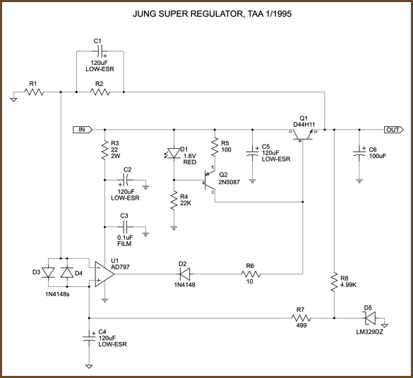
It seems that a few other people with a lot more credentials than me use a capacitor in that position, for instance the Jung super regulator?
Jung regulator is a series-pass and not a shunt.
Jung regulator is a series-pass and not a shunt.
Yes, I showed the first thing that came up in the search, my mistake.
OK, let's correct Broskie and Borbely then.
http://www.tubecad.com/2007/06/blog0109.htm
http://www.borbelyaudio.com/psshunt.asp
An externally hosted image should be here but it was not working when we last tested it.
Is this better? Though I don't know if any of them two is a certified electrical engineer.
@hurtig
I respect all the experience and knowledge you have. It would be better if you showed evidence, point to EE articles, rather than titles and certification.
@Ikoflexer!
We also simulated our circuit in PSpice, and came out with completely different graphs.
Also the circuit will go into oscilation when decoupled, and theoretically it has to do so. Even non optimized layout can cause oscillating, so I think we could have some software problem here.
Which simulation tool are you using?
Btw.
FET´s will never find their way into this project, as they can be heard no matter where they are used. This is intentionally kept completely bipolar.
Hurtig is a certified engineer.
Last edited:
Jung regulator is a series-pass and not a shunt.
Precisely!
And therefor it is quite normal to decouple.
Our digital supplies are series regulators, because even though a shunt is very fast, it still is not fast enough for digital logic.
So ceramic decoupling is mandatory, and that does not go with shunts.
Last edited:
Main issue : you are arrogant. Look also at how you polluted the Buffalo thread.
Next : this thread is 8 months old. Walk the talk man!!
This is my last post here.
Thanks

The simulation was not oscillating. The 0R1 resistor I use for easy measuring the current through the shunt, it does not affect output impedance or anything else. Nor does the shunt capacitor. Removing them gives exactly the same results as I posted earlier.
Why didn't you just put in a current measurement probe, insteed of changing the circuit??
It seems that a few other people with a lot more credentials than me use a capacitor in that position, for instance the Jung super regulator?
Better tell me what you used in your simulations, I'll use the same. Unless it's a secret.
I use ltspice.
That is not what I claim. What I said is that your claims are not in tune with my simulations.
The really dark side is not of diyaudio. The reason why I put even one minute in this is because there are people without the technical background who would accept your claims sight unseen. If your circuit is indeed what you say it is, you should be happy that I'm helping you get credibility. There is nothing more credible than independent tests of one's design.
Well, first of all. I do not know LTSpice that well. I always used PSpice/OrCAD, since this is the state of art simulator. Guess no one will argue against that

About the schematic.... I just draw tghe schematic in OrCAD again, to ensure that I did not do anything wrong. The design i simulated is based on BFR92A, BC856B and the good old BD136 as the shunting element. I have attached the schematic.
Also attached is the result when simulating the impedance.
To perform the impedance-simulation, I stimulated the output by a 1mA AC generator. In the measurement-window, I multiplied the curser-value by 1000. This way the numeric value on the Y-axis is the numeric value of the impedance. At 100kHz you will see, that the impedance is 5,8381milliohms.
As you notice, the impedance starts rising above 1MHz. In practical implementation, I actually measured the impedance to be flat up to approx 10MHz, being better than the simulation.
Last but not least, I added the PSRR simulation. To do this I stimulated the input voltage of the regulator with a 1 volt AC generator.
In the measurement-window, I made the DB calculation on the reciprocal value. This gives you the PSRR.
As you can see, the PSRR at 100Hz is 176dB.
In real life, measurements has shown that this is not possible to achieve. Most likely because these figures are only possible when you have absolutely zero impedance in the PCB tracks, which isn't possible (Even in woodoo audio). I don't remember the precise figures from the measurement. But as I recall, it's about 130dB
So again... If you do use a state of art simulator, and not some freeware/low spec version on the real schematic... You will get the right results.
Next time, please do the homework, before you accuse us of cheating
Attachments

Now we're getting somewhere. Can you please post the impedance plot from 0 to 25mOhm on the Y axis?
You cannot point to a post where I accuse you of cheating, so don't say that. Which one of us is doing whose homework? Think about it.
(ltspice is more than adequate for a simple impedance plot.)
You cannot point to a post where I accuse you of cheating, so don't say that. Which one of us is doing whose homework? Think about it.
(ltspice is more than adequate for a simple impedance plot.)
The simulations are in fact pretty cool
But the most important part is the sonic performance.
Before the decission about shunts were taken, we fiddled around with very nice series regs., but no matter what, it seemed like an endless task to design a powersupply, that did not annoy or collorate the sound in some way afterall. The shunts simply solved theese problems the moment they came about.
In the resulting sound you simply feel that the Q is equal from the very buttom end and up. It isn´t even possible to say whether the effect is biggest in the lows or in the highs, you just experience that every single note/tone or what ever you might call it, is reproduced in a natural and integer way.
You might call it tonal integrity, some will experience it as natural timbre, to me it is just the lack of resonance and uncontrolled behavior, which is perfectly underlined by both simulations and measurements.
The downside of this is heat, in this case almost 3 kg. aluminium with a pretty large surface runs @ 40 dgr. C on the outside.
But that´s life.
Now we're getting somewhere. Can you please post the impedance plot from 0 to 25mOhm on the Y axis?
You cannot point to a post where I accuse you of cheating, so don't say that. Which one of us is doing whose homework? Think about it.
(ltspice is more than adequate for a simple impedance plot.)
What's your point??
Wanna build this design or not??
As KvK says, the sonic performance is the most important issue in this DAC.
If you are more into discussing technical issues, feel free to to that. That's just not the idea of this DAC.
If your main interest is optaining the best possible sound, this DAC may very well be it. And again...: That's what we were seeking

BTW: I don't believe LTSpice is adequate for simulation on that much. It's OK as a guideline. But if you need to go deeper into analyzing, you need something better.
Last edited:
You post in a diy forum. Do you really expect the discussion to stay non-technical? If you did, then why throw around figures of output impedance?
You still didn't show your simulation results for Zout from 0 to 25mOhm. Surely you have nothing to hide?
Don't get angry. Not good for your health. We're just comparing technical results; as an engineer, you know that's normal, and even recommended.
Regards
You still didn't show your simulation results for Zout from 0 to 25mOhm. Surely you have nothing to hide?
Don't get angry. Not good for your health. We're just comparing technical results; as an engineer, you know that's normal, and even recommended.
Regards
You post in a diy forum. Do you really expect the discussion to stay non-technical? If you did, then why throw around figures of output impedance?
You still didn't show your simulation results for Zout from 0 to 25mOhm. Surely you have nothing to hide?
Don't get angry. Not good for your health. We're just comparing technical results; as an engineer, you know that's normal, and even recommended.
Regards
Actually you should not ask for the simulation. Go for the real life performance. Build the shunt yourself and do some measurements. Then you will find that what I say is true.
Maybe I was wrong in assuming, that people in here are seeking the best sonic performance... Are you really more into technical stuff than sonic performance??
@Ikoflexer!
Sorry if you feel that any of us seems a bit edgy on this.
The point is, that we had every single step, and every single component thrown into the game, along with hundreds of components and circuits discarded already. You might try, but you won´t find any basic flaws like the one in question.
You are welcome to build the DAC yourself, we can provide PCB´s if needed.
I have seen something like that with >10k$ audio equipment and maybe this is what your DAC4½ is actually destined for (commercial Danish made Hi-Fi can be pretty good and expensive). Or what do you actually have in mind with it?
As it is way beyond my competence to do prototyping, I greatly appreciate and rely on the effort and intellect that many people put into the design and realization of diy circuits. Especially, if kit versions are also made available to hobby diyers for a reasonable price.
I'm sure that Buffalo is not perfect and that the mods that some of us are doing is not going to make it so. Nevertheless, its for real, sounding great (IMO) and will do just fine until something significantly better comes up.
Cheers,
Nic
Exactly!
You will find the solutions chosen in only a handfull of very expensive DACs, and even then, you´ll hardly find shunt regs, as they run very hot, and you won´t have any busty electrolytic capacitors with your own nametag on it to show the world.
It is a no compromise project where every possible alternative has been tried out.
Even transformer type and size, which both are crusial to the performance, you cannot use any type of transformer, and suspect top notch performance, as they isolate very different. This is also the reason that everything except transformers is placed on a single PCB, only the clock circuit is also a very small ad on pcb, but with no leads, and placed excactly as close to the upsampler as could be with on board placement. This because we wanted to keep this issue open as long as possible, and maybe it can later be updated, if anything usefull should occur.
But basicly anything from powercord to RCA receptacles has been considered and tried out. Actually real 75 Ohm Canare receptacles for the SPDIF has been considered and tried out.
The open issues at this time are very few. We´ve been thinking of various clocks, but until now we´ve settled for an oscillator, which we find the best. But maybe different oscillators will be subject for experiments later on.
Of course I´d clame it to be a very good DAC, as Hurtig and I spend so much time optimising parameters, event those people told us were unimportant, but they actually became important as the proces went on. As an example I can tell, that first when you have an analog stage capable of passing throug the subtle nuances and details, you´ll know how important digital powersupply is. Thus 7 separate digital regulators of which 5 are discrete.
We made this DAC with one aim only, namely to surpas anything, as none of us really have been pleased with comercial DACs, as we very often have found signs of them beeing rushed into the market.
We hope that others can experience the same as we did with this DAC. I can asure though that it is capable of some things that at least I did never hear earlier from digital audio. I.e both the resolution, 3D, effortlessnes and power of anything from the deepest lows and up are remarkable as well as the freedom of resonance .
Last edited:
do you have an estimate when your smd and cheaper diy dac will be available? i know it s that it s against your convictions to rush things but as i see it (you talked about the clock yet to be determined in the other other thread) about clock you still have a couple years of tweaking to do...right?
Last edited:
Heat
Wow! That's a lot of heat!
The downside of this is heat, in this case almost 3 kg. aluminium with a pretty large surface runs @ 40 dgr. C on the outside.
But that´s life.
Wow! That's a lot of heat!
do you have an estimate when your smd and cheaper diy dac will be available? i know it s that it s against your convictions to rush things but as i see it (you talked about the clock yet to be determined in the other other thread) about clock you still have a couple years of tweaking to do...right?
Not realy! The optimum goal is in sight

Since pretty much fixed solutions is at stake, it is a lot faster to get to the point which the ambitions aimed at.
The "simple" DAC will be nice, and with very special options ie. the choise between normal op-amps implementation, and the implementation of an NFB op-amp (AD844).
PSU´s will be decent, and the whole thing will be on one single board.
We did not yet decide if it is going to be 24 or 32 bit though.
I hope 24 bit is going to be NRND soon, making the choise easy
.But I do not think we will be that lucky, so it realy is a matter of the chips available. By now we have got samples of AK4399, but it is a 5V design, and the only 32 bit up-sampler available is CS8421, which is a 2,5V design. They just do not fit very well together.
As an alternative the ESS Sabre DAC could be an option with build in ASRC and reciever, but we do not know a lot about it yet.
So either it is going to be CS8416, AD1896, CS4398 and then the new analog stage, or CS8416, CS8421 and AK4399 as a 32 bit option.
We are arguing about this, and still both of us are waiting for the other one getting tired and giving in at last.
I hope this will happen in this decade at least
Last edited:
Wow! That's a lot of heat!
So it is!
Most DIYérs will be suprised of the heat generated by shunts or class A.
Most manufacturers don´t even have an idea of it
As the matter of fact, I won a lawsuit against Densen Audio Technologies, who claimed some of their amplifiers to be partly class A which they proved not to be at all.
Anyone knowing of the heat probs of class A would know by sight, but Densen really thougt they were right

They weren´t.
http://densen.dk/index.php?page=products&produkt=b175
They do not state the calss A power anylonger though, so at least they became a bit more honest towards ratings.
- Status
- Not open for further replies.
- Home
- Source & Line
- Digital Line Level
- DAC project completed