Hi!
After some succesfull solid state projects some years ago, I thought it would be fun to build something with tubes.
I really like my Zen amp and don't have the money yet to buy some good output trannies (i think), so i'll start with a tube preamp first.
I have some ECL86 from an old radio, so I'd like to make a preamp with these. The Pass Zen amp has quite low input impedance but since the ECL86 has half a EL84 (if I am correct) i thought it would have enough power to drive it.
I found a schematic for a ECL86 preamp here:
ECL86 preamp (in french)
Anyone any suggestions? Or could anyone point me to a thread or link with a list to think about when building your first tube amp.
Thanks, Hans-Willem
GAIN
Hi,
That preamp will have a mu of 100 in mu-follower configuration which is way too much for a CDP.
The ECL86/6GW8 comprises 1/2 ECC83/12AX7A and a EL84/6BQ5.
While the output impedance will be lower then a classic anode follower it will be far from ideal to drive the Zen + I/C.
Personally I'd rather build a small SE amp with a pair of those tubes,it would drive the most difficult headphone with aplomb.
Cheers,")
Hi,
That preamp will have a mu of 100 in mu-follower configuration which is way too much for a CDP.
The ECL86/6GW8 comprises 1/2 ECC83/12AX7A and a EL84/6BQ5.
While the output impedance will be lower then a classic anode follower it will be far from ideal to drive the Zen + I/C.
Personally I'd rather build a small SE amp with a pair of those tubes,it would drive the most difficult headphone with aplomb.
Cheers,
I built exactly the same one and I don't regret it at all.
This schematic comes from a French magazine called "LED" which provide generally more high-end (and costly) projects than any magazine I'm aware of.
I haven't built many preamp in the past, however I can assure you that I was quite amazed by it. No "hum", no background noise, well, no noise at all even at full power.
If you're beginning like me, this is an ideal project
1. The PCB is well designed
2. No many components
3. Cheap and easy to find power tranformer (mine is Hammond 269GX)
4. Results garanteed
However, high voltage capacitors are quite expensive and use only good resistors.
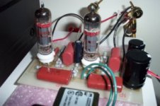
Here's mine. The only thing left is to build a nice enclosure as nice as Peter Daniel's one with his Acrylic GainClone
The fdegrove's comments seems pertinent but I haven't tried my Preamp with Zen.... However mine's connected to a TDA7294 based amp and it seems to work fine. Also, I had to add a resistor along my volume potentiometer because the volume was way too loud past 1/16 turn
This schematic comes from a French magazine called "LED" which provide generally more high-end (and costly) projects than any magazine I'm aware of.
I haven't built many preamp in the past, however I can assure you that I was quite amazed by it. No "hum", no background noise, well, no noise at all even at full power.
If you're beginning like me, this is an ideal project
1. The PCB is well designed
2. No many components
3. Cheap and easy to find power tranformer (mine is Hammond 269GX)
4. Results garanteed
However, high voltage capacitors are quite expensive and use only good resistors.
Here's mine. The only thing left is to build a nice enclosure as nice as Peter Daniel's one with his Acrylic GainClone
The fdegrove's comments seems pertinent but I haven't tried my Preamp with Zen.... However mine's connected to a TDA7294 based amp and it seems to work fine. Also, I had to add a resistor along my volume potentiometer because the volume was way too loud past 1/16 turn
Attachments
Zin.
Hi,
That would only act as a voltage divider.
It would by no means make the input impedance of the amp higher.
Cheers,
Hi,
How about if i put a resistor in series with the output to virtually make the imput impedance of the zen higher?
That would only act as a voltage divider.
It would by no means make the input impedance of the amp higher.
Cheers,
Elkaid said:Schematic for the "famous", "strange", "odd" and "useless"
Not useless at all... totally funky. An SRPP with a pentode on the top. You should try disconnecting C10/C11 and see if things get better. Should lower the gain, give you a little regenerative feedback and eliminate a cap from the circuit.
dave
Is this the Preamp you are discussing.Hanzwillem said:Hi!
I found a schematic for a ECL86 preamp here:
ECL86 preamp (in french)
Anyone any suggestions? Or could anyone point me to a thread or link with a list to think about when building your first tube amp.
Thanks, Hans-Willem
Is this a "normal" and good application,
if I want to try to build my own ECL86 preamp?
Any alternatives?
halojoy - likes to SEE the circuits
Attachments
Re: Re: ECL86 preamp?
Creative is probably a better description. Good, well build it and see... we have one thumbs up in this thread and it was good enuff that the French magazine published it.
Pretty simple...
dave
halojoy said:Is this a "normal" and good application,
if I want to try to build my own ECL86 preamp?
Creative is probably a better description. Good, well build it and see... we have one thumbs up in this thread and it was good enuff that the French magazine published it.
Pretty simple...
dave
planet10 said:An SRPP with a pentode on the top.
Now that i went back to actually attempt to understand what it says, they are calling it a Mu-follower.
dave
LE MAXIMUM.
Hi,
They probably named it that way because of the maximum gain one has using the mu-follower.
Some remarks:
If you decide to get rid of the cathode bypass caps you need also to consider a considerable rise in output impedance (Zo).
On the circuit the gain is already reduced by the voltage divider at the input.
You can change gain setting there if you like.
Also,at switch on the output cap will charge to ~ 6VDC before settling to 0.
So to prevent this I would recommend using a mute switch at the output and have it engaged for at least one minute prior to operation.
All coupling caps should be of premium Q and it would not hurt to make the HT rails independent from each other to avoid IMD and crosstalk.
It will take a second xformer and a handful of components.
Alternatively one could use a pair of chokes to split the B+ into L + R channels.
Cheers,
Re: LE MAXIMUM.
Thanx Frank.
Its nice to have someone who actually knows where the electrons go step in -- me i know just enuff to be dangerous.
dave
fdegrove said:Some remarks:
Thanx Frank.
Its nice to have someone who actually knows where the electrons go step in -- me i know just enuff to be dangerous.
dave
If you have any troubles reading French, maybe you should try Altavista's Babelfish
BabelFish
and then enter the following URL
http://dan.bellity.online.fr/haute-fidelite/DIY/LED-mu-follower/DIY-mu-follower.html
I hope this will give you an idea of what the article means.
Regards
BabelFish
and then enter the following URL
http://dan.bellity.online.fr/haute-fidelite/DIY/LED-mu-follower/DIY-mu-follower.html
I hope this will give you an idea of what the article means.
Regards
LE CAIDE
Hi,
With all due respect...the circuit speaks for itself.
Although the mu-follower as such is a fine circuit, no doubt in my mind about that,the preamp using the ECL86 is far better suited as a phono stage-provided an RIAA correction of sorts-then a preamp stage for a digital source.
As it is,consider it as a little exercise in mu-follower topology with little real life use as a preamp.
No translation sw is going to change that.
However,with a bit of imagination and some math you could use a EL86/6CW5 as a penthode on top and a 6CG7/6FQ7 on the bottom for a low cost line stage,for example.
It would still have gain to burn though,so if you want to better that go for a 12B4A or the 6C19P for even better line drive.
There are a myriad of combinations possible depending on your n eeds and imagination.
Consider a well designed PSU to go with it and you have yourself a winner.
Cheers,
Hi,
If you have any troubles reading French, maybe you should try Altavista's Babelfish
With all due respect...the circuit speaks for itself.
Although the mu-follower as such is a fine circuit, no doubt in my mind about that,the preamp using the ECL86 is far better suited as a phono stage-provided an RIAA correction of sorts-then a preamp stage for a digital source.
As it is,consider it as a little exercise in mu-follower topology with little real life use as a preamp.
No translation sw is going to change that.
However,with a bit of imagination and some math you could use a EL86/6CW5 as a penthode on top and a 6CG7/6FQ7 on the bottom for a low cost line stage,for example.
It would still have gain to burn though,so if you want to better that go for a 12B4A or the 6C19P for even better line drive.
There are a myriad of combinations possible depending on your n eeds and imagination.
Consider a well designed PSU to go with it and you have yourself a winner.
Cheers,
Thanks fdegrove for the comments
I didn't meant to insult anyone here when suggesting a way to translate comments provided along the schematic... I thought some people could be interested. well, anyway...
So concerning the ECL86 preamp if I understand you correctly, it's a big mistake from me to have built this preamplifier when used along a CD player ? What characteristics are we looking for a phono preamp versus a cd player preamp ?
I chose this design because it was the simplest I could find last summer and I had already the power transformer.
Do you mean that ECL86 is too powerful ? Or the schematic is a based on a poor concept ? I would just to know why it is a bad preamp so I will not make the same mistake twice...
(Several people here has already mentionned that this amp was strange and odd but without any real explanations... )
Any clarifications would be appreciated from all of you guys !
Regards,
Elkaid said:Any clarifications would be appreciated from all of you guys !
Don't let Frank discourage you...you built the pre -- are you enjoying it? Does it help you get to the music?
Frank is using an ECC83 in his Ultimate Pre-amp, many would pooh-pooh that tube choice, but i am sure that won't dscourgae him.
Pushing against the "established" conventions is how great new discoveries are made (and at least as many flops) -- witness the gainclone.
dave
Ok ! Thanks ! Quite encouraging
I'm quite intrigued by the suggested mods and I would need more explanations about them...
Which caps are the cathode bypass ? (cathode is the tube's grid ?)
Which characteristic will be improved by this mod ?
Is it with the removed cathode bypass caps or with the original schematic ?
Also, I'm currently using a 2 X 225V 65ma + 6.3V 2.5A transformer. When the preamp is on for a long time, the transformer is getting pretty warm. I'm still able to lay my hand on it. I would say around 45-50 degrees Celcius. Is it dangerous ? Should I get a transformer with higher specs ? (Although in the article, the author suggested a transfomer almost identical to mine)
Thanks again for you support !
Regards,
I'm quite intrigued by the suggested mods and I would need more explanations about them...
fdegrove
If you decide to get rid of the cathode bypass caps you need also to consider a considerable rise in output impedance (Zo).
Which caps are the cathode bypass ? (cathode is the tube's grid ?)
Which characteristic will be improved by this mod ?
fdegrove
Also,at switch on the output cap will charge to ~ 6VDC before settling to 0.
Is it with the removed cathode bypass caps or with the original schematic ?
Also, I'm currently using a 2 X 225V 65ma + 6.3V 2.5A transformer. When the preamp is on for a long time, the transformer is getting pretty warm. I'm still able to lay my hand on it. I would say around 45-50 degrees Celcius. Is it dangerous ? Should I get a transformer with higher specs ? (Although in the article, the author suggested a transfomer almost identical to mine)
Thanks again for you support !
Regards,
ECL86
Hi,
C10/C11 connected at pin # 2 of the socket, you'll have a resistor to ground and a cap in // with that.
Removing the cap will cause some degenerative feedback, this in turn will linearise it at the expense of a reduction in gain and an increase in output impedance.
No, the output caps will charge at switch on if there no resistor at the output shunting the charge to ground.
That's quite normal.
Cheers,
Hi,
Which caps are the cathode bypass ? (cathode is the tube's grid ?)
C10/C11 connected at pin # 2 of the socket, you'll have a resistor to ground and a cap in // with that.
Which characteristic will be improved by this mod ?
Removing the cap will cause some degenerative feedback, this in turn will linearise it at the expense of a reduction in gain and an increase in output impedance.
Is it with the removed cathode bypass caps or with the original schematic ?
No, the output caps will charge at switch on if there no resistor at the output shunting the charge to ground.
I would say around 45-50 degrees Celcius.
That's quite normal.
Cheers,
12AX7A/ECC83.
Hi,
For info:
The ECC83/12AX7A is used as an error amplifier in the regulator of the PSU in that design.
At the start it used an ECC807 (mu 140 per section) but that tube has become obsolete for many yers now.
The full preamp, i.e. with the phono section included does use a 12AX7A/ECC83 per channel.
When the scans are ready I'll publish it too.
Although I have nothing against that tube, it's best suited for applications where high gain is absolutely necessary.
Unfortunately high gain comes at the expense of linearity...no free lunch.
Cheers,
Hi,
Frank is using an ECC83 in his Ultimate Pre-amp, many would pooh-pooh that tube choice, but i am sure that won't dscourgae him.
For info:
The ECC83/12AX7A is used as an error amplifier in the regulator of the PSU in that design.
At the start it used an ECC807 (mu 140 per section) but that tube has become obsolete for many yers now.
The full preamp, i.e. with the phono section included does use a 12AX7A/ECC83 per channel.
When the scans are ready I'll publish it too.
Although I have nothing against that tube, it's best suited for applications where high gain is absolutely necessary.
Unfortunately high gain comes at the expense of linearity...no free lunch.
Cheers,
Re: 12AX7A/ECC83.
That's a relief... you had me worried there Frank
dave
fdegrove said:The ECC83/12AX7A is used as an error amplifier in the regulator of the PSU in that design.
That's a relief... you had me worried there Frank
dave
- Status
- This old topic is closed. If you want to reopen this topic, contact a moderator using the "Report Post" button.
- Home
- Amplifiers
- Tubes / Valves
- ECL86 preamp?