I was thinking on a Shunt Regulator for the input stage. As the current taken is in the 20 mA range, implying a 30-40mA for the Shunt CCS, the dissipation should not be exceptionally huge. But soundwise, the shunts always brought a big improvement according to my experience.
Doesn't a shunt regulator usually imply a fixed output voltage, which would mean setting the voltage for the front end several volts lower than the main rails?I was thinking on a Shunt Regulator for the input stage. As the current taken is in the 20 mA range, implying a 30-40mA for the Shunt CCS, the dissipation should not be exceptionally huge. But soundwise, the shunts always brought a big improvement according to my experience.
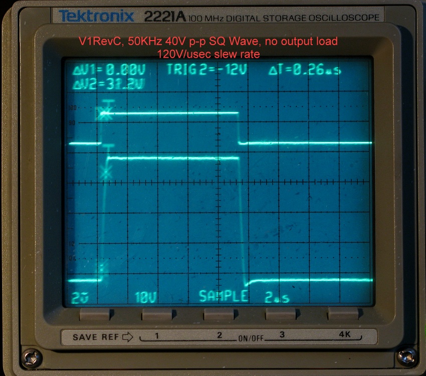
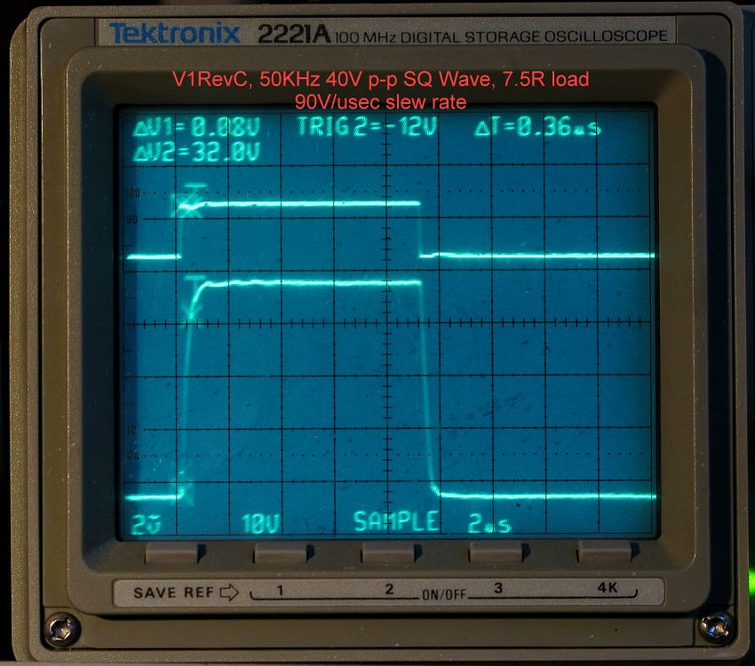
Test Results, Slew Rate
*** Picture Upload is failing today, so I had to compromise... sorry for the waste of bandwidth! ***
This should be considered "Typical" slew rate with 35V supply, because for consistency, the test conditions were kept the same as for the other tests above. Nevertheless, 100V/usec under these conditions, from a circuit that Lazy Cat calls the "Very Simple" version of his Symmetrical Amp designs, and a TH board which is much larger than his original!
BC546C/BC556C input
KSA1381E/KSC3503E VAS
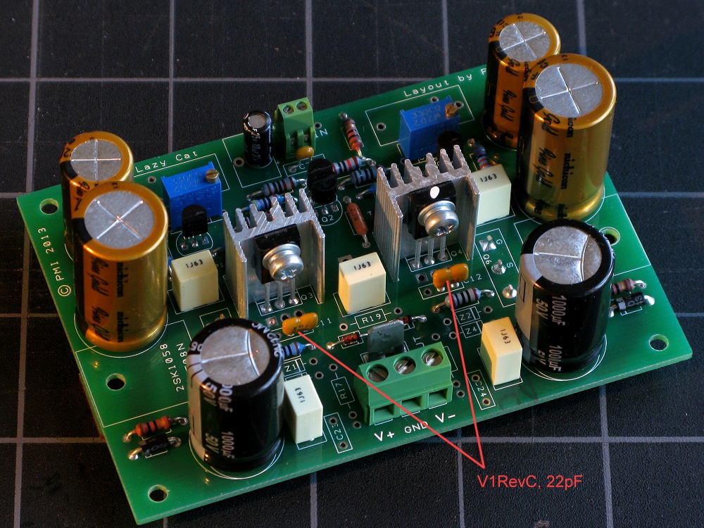
22 pf caps at the VAS
Actual slew rate calculation was 120V/usec with no load, and ~90V/usec with 7.5R resistive load. Test was run with +/- 35V supply, 50KHz 40V pk-to-pk square wave.
*** Picture Upload is failing today, so I had to compromise... sorry for the waste of bandwidth! ***
This should be considered "Typical" slew rate with 35V supply, because for consistency, the test conditions were kept the same as for the other tests above. Nevertheless, 100V/usec under these conditions, from a circuit that Lazy Cat calls the "Very Simple" version of his Symmetrical Amp designs, and a TH board which is much larger than his original!
BC546C/BC556C input
KSA1381E/KSC3503E VAS
22 pf caps at the VAS
Actual slew rate calculation was 120V/usec with no load, and ~90V/usec with 7.5R resistive load. Test was run with +/- 35V supply, 50KHz 40V pk-to-pk square wave.
Doesn't a shunt regulator usually imply a fixed output voltage, which would mean setting the voltage for the front end several volts lower than the main rails?
Yes, obviously, if you use the same supply for the front end, any kind of regulation means that.
But if you use voltage lift 12-15V above the main supply, that's a better situation: higher voltage than main and regulated. that is a possibility to skip the Resistor-Diode group and use independent front end supply. 2 additional coils on the main transformer, or even one small trafo, 3-4VA with 2 independent 12V-15V output would do the trick for this voltage difference.
of course, it will increase the complexity, but maybe
it adds some audible benefit.I have seen that used somewhere, it is clever, but it is not a common solution....
Input voltage for stabilize transistors circuit come from series connection of main transformer and one auxiliary transformer.
If you are going to use a separate transformer, you may as well get one with an output voltage which is already what you want for the front end.
In general yes, but as you know yourself, the Capacitance Multiplier PSU only needs about 1V, so the power loss is very small.Yes, obviously, if you use the same supply for the front end, any kind of regulation means that.
VSSA can operate fairly close to the rails of the main supply, 3~4V, so there is less to be gained from a higher front end voltage, but still, worth considering, in my opinion.
For a small regulator of any kind, I would tap off the same transformer, but use a small separate bridge, caps, and so on. Since the ~20mA is a tiny current draw, this small supply would operate at close to the peak AC voltage at the secondary. This would only give you 1-2V extra at idle, but it drops very little at higher load, so the difference between the two supplies will increase as the output signal comes closer to the maximum (when you need it the most)
In other words, as load goes up, the ripple at the main supply increases, which lowers the usable output by more than the transformer load regulation. At your front end supply with its 20mA, load stays the same, and the output voltage stays close to the transformer secondary pk...
In theory yes, in practice, not so much. For one thing, the BC550C/560C that people seem to like so much are limited to 45V. (i am using BC546C/BC556C now, so perhaps not an issue). Two of the four 1000uFd caps on the board will have to be rated at 63V instead of 50VBut if you use voltage lift 12-15V above the main supply, that's a better situation: higher voltage than main and regulated. that is a possibility to skip the Resistor-Diode group and use independent front end supply. 2 additional coils on the main transformer, or even one small trafo, 3-4VA with 2 independent 12V-15V output would do the trick for this voltage difference.
I originally intended to put an optional tab on the board for a separate front end supply. (although not as elaborate as Fab's suggestion).
In experimenting with different combinations, using my bench supply for the front end, and other power supplies for the main power, I could not discern a difference once I switched to the Cap Multi filtering.
Yes, you are right, but probably I misspelled my intention; the additional voltage is to feed the shunt, that needs 6-8V drop for normal operation. If you adjust the shunt output to 5V+Vmain, you are still in reasonable safe limits. of course (you are right again) the voltage drops under load, so the regulated output of the shunt can be even lower in practice.
The advantage of the shunt is that in confines the currents in the stage it feeds, and this is an advantage for a "poorer" PSRR front-end. And the sound is great, I have not believed until Paradise preamp sounded for the first time in my own house.
Well, it's just an idea that justifies additional tabs for front-end supply. I guess you already know I don't intend to go way too off-topic.
I am quite busy these days with Cap Multiplier for X-VSSA. P2P of course, this time also with some SMD's - for the true hardcore fans of P2P
OK, I missed that, probably b/c I keep thinking to maintain lowest voltage drop/power loss possible.Yes, you are right, but probably I misspelled my intention; the additional voltage is to feed the shunt, that needs 6-8V drop for normal operation.
Well, a preamp is a completely different story... and I envy that build, btw... I will raise that on my to do list, let's give it a shot. All that is really needed is to solder a couple wires in place of the resistor, and omit the diode.The advantage of the shunt is that in confines the currents in the stage it feeds, and this is an advantage for a "poorer" PSRR front-end. And the sound is great, I have not believed until Paradise preamp sounded for the first time in my own house.
If there is a revision, I will add holes for an extra tab... you and Fab have talked me into it,Well, it's just an idea that justifies additional tabs for front-end supply. I guess you already know I don't intend to go way too off-topic.
OMG! I though I was the Luddite for trying to keep the through-hole alternative alive...I am quite busy these days with Cap Multiplier for X-VSSA. P2P of course, this time also with some SMD's - for the true hardcore fans of P2P
Hi PMI, Thanks again for your help with the VSSA, I found to advanced the project of LC, that is amazing. I have plenty of questions. But I will share few of them:
Do you have boards for sale? Is possible to get Lateral fet in affordable price, in matched pairs, is possible to use ALF08PN, Do you have the KSA1381E/KSC3503E matched pair for sale?
Many thanks for the work. Is easy find a job finish like the yours and The LC'one. I would like to have more time for experiment and find some goals, with people like you the cook book is finish and ready.
OMG! I though I was the Luddite for trying to keep the through-hole alternative alive...
Well, I use SMD's where space can be saved, and in some cases I find the P2P solution much solid with them. I have my P2P boards with square islands instead of round ones and that helps, especially if using 0805 format. for example, I have collector of the current mirror and drain of the MOSFET of the differential amplifier in a same hole, only one island away from the Grid of the power MOSFET, so a 8R2 can simply join these two points. I find this really handy... probably not while debugging, but this CM is already a tested solution Will post later some pictures in the cap multiplier thread...
Hi PMI, Thanks again for your help with the VSSA, I found to advanced the project of LC, that is amazing. I have plenty of questions. But I will share few of them:
Do you have boards for sale? Is possible to get Lateral fet in affordable price, in matched pairs, is possible to use ALF08PN, Do you have the KSA1381E/KSC3503E matched pair for sale?
Many thanks for the work. Is easy find a job finish like the yours and The LC'one. I would like to have more time for experiment and find some goals, with people like you the cook book is finish and ready.
I have more boards on order, but so far I only have enough on hand for the first few people who have been discussing the through hole version (and helping, with their input and comments). Some of them have been waiting for a long time, so they get them first...Do you have boards for sale?
If there is continued interest, I will open a Group Buy thread, but in any case it is not likely to be for hundreds of boards like LC. More a matter of keeping a Through-Hole version alive, especially now that LC has moved on to bigger things,
.The board only has one pair of complementary lateral fets. As far as I know, complementary fets cannot be matched (N-channel to P-channel) in a way that is meaningful for this circuit. Only same type (N-channel to N-channel, and P-channel to P-channel) can be matched, for dual-pair boards.Is possible to get Lateral fet in affordable price, in matched pairs
SK1058 and SJ162 cost about $5 each
ALF08N16 and ALF08P16 about $7 each (in the US)
I have enough of the KSC3503EKSA1381E for those people who want to use them. Matching will be dicussed in a later post, but I believe that Lazy Cat, as well as someone else, have both posted that you do not need a very close match. In any case, the hfe curves for the two devices do not have the same slope, so a perfect match is only meaningful if you intentionally calibrate to the bias current used to match the parts (this would go against the reason for calibration in the first place).Do you have the KSA1381E/KSC3503E matched pair for sale?
A match within 5~10% is fairly easy to get, but so far only with one date code of KSA1381-E (B31/Korea). The KSC3503-E are old stock (J20/US).
I don't have time to match parts myself, but I am looking into the cost of having someone else check pairs to make sure they are in that range. (Quite a few people would have to want to buy them to make it worth someone's time though).
Parts selection / matching from a population of stock
So, speaking of matching, I finally got out my Locky_z curve tracer and hooked it up. I just have a few questions about matching components to a higher level than quick and dirty methods allow.
Ideally, we would like to see both 'Vbe vs Ic' and 'hFE vs Ic' curves be a near point for point match when selecting parts. The likelihood of this is low, especially when looking for similar characteristics between NPN and PNP. Given the choice, which is the preferred scenario?
A) A well matched 'Vbe vs Ic' curve with a greater deviation in the 'hFE vs Ic' curve.
OR
B) Having good alignment of the 'hFE vs Ic' curve but more deviation between the 'Vbe vs Ic' curve.
My knee jerk reaction is to select the best match in the 'Vbe vs Ic' curve and allow some difference in hFE rather than the other way round. As far as gain goes, so long as it is relatively flat over the region of operation then no harm no foul with respect to differences in absolute magnitude. Opinions on this? Am I out to lunch or near the mark?
In your case, all you need is Hfe vs Ic.
No need for Vbe vs Ic, It`s needed when you run paralel devices, to match their syncronized turn on point...
In your case, all you need is Hfe vs Ic.
No need for Vbe vs Ic, It`s needed when you run paralel devices, to match their syncronized turn on point...
Yes, that makes sense. Guess I was not thinking about it correctly when I first saw some curves.
I think our selection of VAS PNP and NPN devices may not have curves with the same slope. SA1381 looks flat in the datasheet. SC3503 is better-behaved than most, with the ideally flat part between 10 and 30 mA, centered on about 20 mA - again, in the datasheet.
The typical recommended VAS bias is between12 and 20 mA (12, by LC).
So, the most useful information would be to confirm that the curves are flat in the region we think, because the datasheet is a lot older than the parts we are buying now (useful to me, at least).
If the curves look as we think they do, then a single point match centered around the likely bias current, +/- 10% is good enough for me. If the curves do not look like the datasheet, it becomes a different problem.
Long story short, if Jason can plot the curves of a few real devices, ones we can get out hands on, old stock or new, it would be very useful. We would not have to guess whether we are biasing that pair at the right point.
@ Jason: Should I be planning to send you a few extra parts, or are you primarily looking toward an alternative to the SA1831/SC3503?
I was trying to post some plots but the issues with the forum and uploads have thwarted my efforts, at least as of last night. I will try again later and certainly over the weekend to put up some curves. Also, since I just began to use the device I'm discovering mine may have a crap relay on it, some curves are definitely off when plotting P-channel / PNP devices but the issue seems to be worse at higher currents. When I can post images I'm hoping to get some guidance or confirmation from Locky_z on trouble shooting the issue.
I would like to be able to compare the KSA1381 / KSC3503 both sonically and via their scope traces to potential alternatives. I'm not sure my new USB scope has the kind of resolution to be meaningful so I will likely be visually evaluating with my old Tektronix digital scope. I'd be more than happy to take curves from the devices you send but extras are not necessary unless you want specific tests or comparisons made that would be facilitated by having extras on hand.
I should have considered four boards, one pair reference and one pair experimental.
What devices do those two graphs represent? Do you mean one graph is Sanyo, and another graph is Fairchild? Or is one graph KSA1381-E, and another KSC3503-E? Or other devices alltogether?These are very linear parts,the old stock Sanyo 2SC are not as consistent as the newer fairchild KSA devices...

- Home
- Amplifiers
- Solid State
- VSSA Through-Hole-PCB build thread