Jay,
Here is an interesting comparison. I only had time for clip 1, but you might get a good idea of differences.
Thanks, X.
Actually, there are quality attributes or variables that cannot be seen easily from clip-1. But clip-1 is probably the most suitable for perceiving distortion (that bass can sound fatiguing. Is it real or synthesizer?).
Comparing FifoCphone with VHEX, it is very obvious that VHEX has a LOT more detail. I think this is understandable as the original C-phone seems to have high noise that puts the details down.
Comparing FifoCphone with Cphone, it is also clear for me that Cphone is lower in distortion and much more enjoyable. And the woodwind seems to have less "second-order harmonics" in hexfet.
Here is the kicker, the Vhex amp actually *added* more dynamics to the music IMO. So perhaps some might say that is a bit un-natural sounding, but it's kind of nice in a way - I could actually hear the different instruments and voices better than the source. Strange.
Hmmm... I didn't notice that. I know that VHEX is very detailed but I don't know if it is better than the source. But this I think is possible especially if you don't use BUFFER in front of the amps... (and the amp for audition)
The standard minimum input impedance of an amp is 50k or 47k. Only VHEX is using 47k resistor in the input. Other amps use 22k, even 10k in VSSA...
If you change the input impedance, I believe it will be audible.
Hi Jay,
Thx for answer, I understand better....
But maybe I am wrong, on the first graph, FX8 Bimo has better bass to 250hz ????
maybe I am wrong, but THD is measured by the VAR between the recorded calibrateed mic and the sound produced by REW at a constant DB and a specified range. On XRK graph it looks like 87-88DB.
I know XRK is very meticulous and the measurements are good quality, but
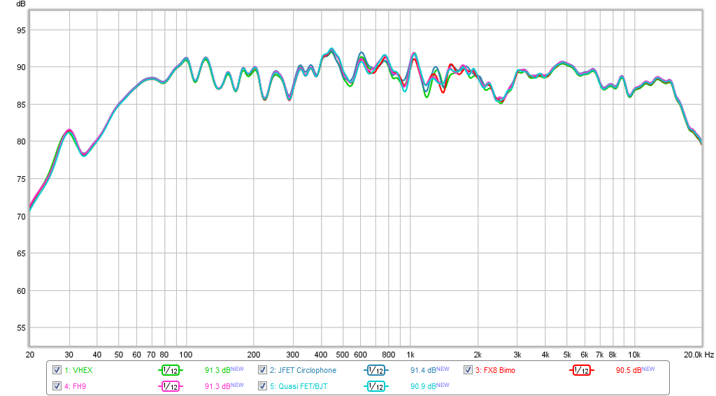
on the graphic, the green curve for VHEX is identified as 91.3DB, but visually it is 'grosso modo' lower than the other curves except at 1.5Khz
The red curve (or the others) looks higher than the VHEX curve and rated at 90.5DB... => The DB shouldn't be higher (try to visually compare the cyan curve and the green curve)?
Is it a graphical effect because all the curves are pretty similar?
Well... I think I need to understand REW graphs
Camelator, can you post or show which picture you are referring to? I couldn't see any comparison between the amps, except the fourth image in the first post which I think is all equal???
but on the graphic, the green curve for VHEX is identified as 91.3DB, but visually it is 'grosso modo' lower than the other curves except at 1.5Khz
The red curve (or the others) looks higher than the VHEX curve and rated at 90.5DB...
Those numbers (91.3, 90.5) are in the frequency response graph.
It is at 1 kHz frequency where the most sensitive is JFET C-phone with 91.4dB and the least sensitive is FX8 with 90.5dB
Last edited:
Camelator, can you post or show which picture you are referring to? I couldn't see any comparison between the amps, except the fourth image in the first post which I think is all equal???
Maybe you are right, the curves look very close.
Those numbers (91.3, 90.5) are in the frequency response graph.
It is in 1 kHz frequency where the most sensitive is JFET C-phone with 91.4dB and the least sensitive is FX8 with 90.5dB
Got it.
Many thx.
So if my understanding is correct, the only way to know the measured dynamics is to watch the slope of the curves ? a small slope means low dynamics and huge slope means high dynamics?
So if my understanding is correct, the only way to know the measured dynamics is to watch the slope of the curves ? a small slope means low dynamics and huge slope means high dynamics?
It is a frequency response. The relative loudness between varying frequency from 20Hz to 20kHz. Ideally this should be a FLAT line. The graph shows that there should be no audible difference due to "no" difference in loudness (or frequency response).
Dynamics, as often used by audiophiles, is a subjective term. There is a technical term, of course, but this is not a common thing to measure. THD+N (distortion and noise) is the common variable to be measured, which also reflect the real dynamics of an amplifier.
Everyone has different ears, and (thus) different preference.
But the very important thing is: EVERYONE can easily hear the difference in bass quality, and everyone love bass. The consequence of this is, if you have to design an amplifier for commercial offering, make sure the bass is good, because the amp will win the customers.

I think, you are the best in this forum when describing of sound. And I agree that most people are looking of the bass quality, first.
Everyone has different ears, and (thus) different preference.
But the very important thing is: EVERYONE can easily hear the difference in bass quality, and everyone love bass. The consequence of this is, if you have to design an amplifier for commercial offering, make sure the bass is good, because the amp will win the customers.
Slightly harder to perceive than bass, but still related with bass, is dynamics/sonic. Hexfet tends to excel at these. The cymbal for example, I think was best with FH9.
THD is very difficult to hear once it is low enough like all the amps in this test. When someone prefer an amp in this test, who knows if it is related with THD or not... For example, I can hear that FH9 has higher distortion, but I cannot prove if that is correct or not.
There are other things which are very difficult to hear, but if you can, you might prefer those attributes. Like naturalness, which is a function of amplifier linearity.
ADD: I should add also that sonic is usually the trade-off for THD. So if you want to reduce THD, you may end up with less sonic.
Good comments that are spot-on Jay. You really do have good ears and the title of "Golden Eared Jay" is still yours. 🙂
The FH9 indeed has a tad more distortion than the others, but not much more as all of these amps have very good low distortion if one were to compare them to commercial offerings with ratings of 0.1% THD at max power. They are all below that I think. The bass dynamics is quite audible and does not show up in frequency response very well. I think a combination of the step response plot and waterfall plot may prove more interesting there. I think an amp's ability to get a square wave right up to a higher frequency will impact dynamics because slew rate will give better attack reproduction.
Hmmm... I didn't notice that. I know that VHEX is very detailed but I don't know if it is better than the source. But this I think is possible especially if you don't use BUFFER in front of the amps... (and the amp for audition)
The standard minimum input impedance of an amp is 50k or 47k. Only VHEX is using 47k resistor in the input. Other amps use 22k, even 10k in VSSA...
If you change the input impedance, I believe it will be audible.
After listening to the tracks with a better headphone (over ear MDRV6) and my class A JLH headphone amp I change my opinion and see that the VHEX does not sound more dynamic than the source. It was the bad headphone-outputs on the stock built in sound card on my laptop that made me think his originally.
The amps in this test are all driven by my CS4398 DAC which has a dedicated Burr Brown OPA2604 op amp powered by clean regulated +/-15vdc rails so I think the output impedance variation from 10k to 47k will not be a big issue. It's got muscle to drive it regardless. Note that amps are using various different input caps: Quasi, FH9, and VHEX+ have 10uF 50v rated MLCC cap bypassed with a 100nF MKT 100v film cap; FX8 and VSSA uses 10uF 250v MKT film cap bypassed with 100nF 450v MKT film cap; Circlophone uses 2.2uF 63v MKT, FiFo Circlophone uses 2.2uF 250v MKT. Do these differences make much of a difference for bass and clarity and dynamics?
Last edited:
Those numbers (91.3, 90.5) are in the frequency response graph.
It is at 1 kHz frequency where the most sensitive is JFET C-phone with 91.4dB and the least sensitive is FX8 with 90.5dB
I was going to post individual HD spectrum plots for each amp - stand by for them later tonight.
"high-k" ceramics - which a 50V 10uF MLCC will certainly be unless it's a size of a coin - doesn't act linearly under certain conditions. Used as an input coupling cap a distortion increase will form in the bass region where attenuation starts to set in.
So generally not the first choice for use as signal capacitors.
So generally not the first choice for use as signal capacitors.
"high-k" ceramics - which a 50V 10uF MLCC will certainly be unless it's a size of a coin - doesn't act linearly under certain conditions. Used as an input coupling cap a distortion increase will form in the bass region where attenuation starts to set in.
So generally not the first choice for use as signal capacitors.
Funny how this is the cap being used on the amps that have the most perceived bass impact and dynamics.
The PCB calls for a little 10uF electrolytic here so I figured this option would be better.
Funny how this is the cap being used on the amps that have the most perceived bass impact and dynamics.
The PCB calls for a little 10uF electrolytic here so I figured this option would be better.
Suggest if your pre (CS4398 DAC) has AC coupling capacitor at output then for all these power amps bypass their input coupling capacitors. That would take out the difference sound signature that seems to be build into capacitor technology : )
Haha,
Now I need to look at the coupling cap used in the DAC output!
If it's what I suspect it is, those two little 10uF electrolytics near the right side of the RCA out jacks may be what is standing in the way of my audio grade cap Nirvana. 😀
Now I need to look at the coupling cap used in the DAC output!
If it's what I suspect it is, those two little 10uF electrolytics near the right side of the RCA out jacks may be what is standing in the way of my audio grade cap Nirvana. 😀
Attachments

Last edited:
I think a combination of the step response plot and waterfall plot may prove more interesting there. I think an amp's ability to get a square wave right up to a higher frequency will impact dynamics because slew rate will give better attack reproduction.
I think so... This is my frustration 🙂 Difficult to analyze the frequency curve
And what I don't understand is the following thing: as far I remember (I am too busy now) REW does not play a random sample: it is rising gradually from lower frequency to upper frequency. So if my understanding is correct, it should be easy for an amplifier and a speaker to follow this line. But what is the response if the frequency suddenly jump from 100hz to 1khz? Is it possible measure that with REW?
I think you need a square wave generator and an O-scope to see if amp is capable of high slew rate. REW will give you derived impulse and step response from FFT which is worth something but not same as seeing a 100 nsec risetime on a 200kHz squarewave.
Here is predicted CFH7 response into purely resistive load on O-scope with 200kHz square wave.
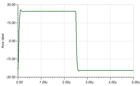
Here is predicted CFH7 response into purely resistive load on O-scope with 200kHz square wave.
Attachments

I think you need a square wave generator and an O-scope to see if amp is capable of high slew rate. REW will give you derived impulse and step response from FFT which is worth something but not same as seeing a 100 nsec risetime on a 200kHz squarewave.
Anyway.... This is related to one of my project with RASPBERRY PI and ADAU1701...
you did a great job (as always) with these boards & measurements.
Many thx xrk & Jay for the answers.
- Status
- Not open for further replies.
- Home
- Amplifiers
- Solid State
- Virtual Audition of Very Simple Quasi MOSFET Amp