ALPS RK 50 Quad Volume Control Wanted
- By domtweaker
- Swap Meet
- 0 Replies
Looking for an Alps RK 50 Quad deck 100 K volume Pot.
Anyone maybe have one
Thank you
Anyone maybe have one
Thank you
|DATA EXPORTED FROM HORNRESP - RESONANCES NOT MASKED

|COMMENT: 18DS115-8 - Input wizard | Front loaded conical horn loudspeaker

|~~~~~~~~~~~~~~~~~~~~~~~~~~~~~~~~~~~~~~~~~~~~~~~~~~~~~~~~~~~~~~~~~~~~~~~~~~~~~~~~~~~~~~~~~~~~~~~~~~~~~~~~

|REQUIRED AKABAK SETTINGS:

|File > Preferences > Physical system constants:

|Sound velocity c = 344m/s
|Medium density rho = 1.205kg/m3

|Sum > Acoustic power:

|Frequency range = 10Hz to 20kHz
|Points = 533
|Input voltage = 2.83V rms
|Integration = 2Pi-sr
|Integration steps = 1 degree ... 1 degree
|Integration method = Cross

|~~~~~~~~~~~~~~~~~~~~~~~~~~~~~~~~~~~~~~~~~~~~~~~~~~~~~~~~~~~~~~~~~~~~~~~~~~~~~~~~~~~~~~~~~~~~~~~~~~~~~~~~

Def_Const |Hornresp Input Parameter Values
{
|Length, area and volume values converted to metres, square metres and cubic metres:

S1  =   330.00e-4;  |Horn segment 1 throat area (sq m)
S2  =   467.00e-4;  |Horn segment 1 mouth area (sq m)

L12 =    92.00e-2;  |Horn segment 1 axial length (m)

Vrc =    74.70e-3;  |Rear chamber volume (cubic m)
Lrc =    76.50e-2;  |Rear chamber average length (m)

Ap  =   300.00e-4;  |Rear chamber port cross-sectional area (sq m)
Lpt =    66.60e-2;  |Rear chamber port tube length (m)

Vtc =  5400.00e-6;  |Throat chamber volume (cubic m)
Atc =  1000.00e-4;  |Throat chamber cross-sectional area (sq m)

|Parameter Conversions:

Sd  = 1210.00e-4;  |Diaphragm area (sq m)

Rp = Sqrt(Ap / Pi);             |Port tube radius (m)
Lpt1 = Lpt + 0.1952 * Pi * Rp;  |Port tube length plus unflanged inlet end correction (m)

Arc = Vrc / Lrc;

Ltc = Vtc / Atc;
}
|~~~~~~~~~~~~~~~~~~~~~~~~~~~~~~~~~~~~~~~~~~~~~~~~~~~~~~~~~~~~~~~~~~~~~~~~~~~~~~~~~~~~~~~~~~~~~~~~~~~~~~~~

|Network node numbers for this horn-loaded vented-box system:

|                        0-Voltage-1
|                                  |
|Radiator(1)-3-Port-4-Chamber-5-Driver-6-Chamber-8-Segment-9-Radiator(2)

|~~~~~~~~~~~~~~~~~~~~~~~~~~~~~~~~~~~~~~~~~~~~~~~~~~~~~~~~~~~~~~~~~~~~~~~~~~~~~~~~~~~~~~~~~~~~~~~~~~~~~~~~

Def_Driver 'Driver'

  Sd=1210.00cm2
  Bl=39.00Tm
  Cms=8.05E-05m/N
  Rms=15.33Ns/m
  fs=30.00Hz  |Mmd = 325.41g not recognised by AkAbak, fs calculated and used instead
  Le=3.85mH
  Re=5.00ohm
  ExpoLe=1

System 'System'

  Driver Def='Driver''Driver'
    Node=1=0=5=6

  Radiator 'Port outlet'
    Node=3
    SD={Ap}
    Label=1

  Duct 'Rear chamber port'
    Node=3=4
    SD={Ap}
    Len={Lpt1}
    Visc=0

  Duct 'Rear chamber'
    Node=4=5
    SD={Arc}
    Len={Lrc}
    Visc=0

  Duct 'Throat chamber'
    Node=6=8
    SD={Atc}
    Len={Ltc}
    Visc=0

  Waveguide 'Horn segment 1'
    Node=8=9
    STh={S1}
    SMo={S2}
    Len={L12}
    Conical

  Radiator 'Horn mouth'
    Node=9
    SD={S2}
    Label=2


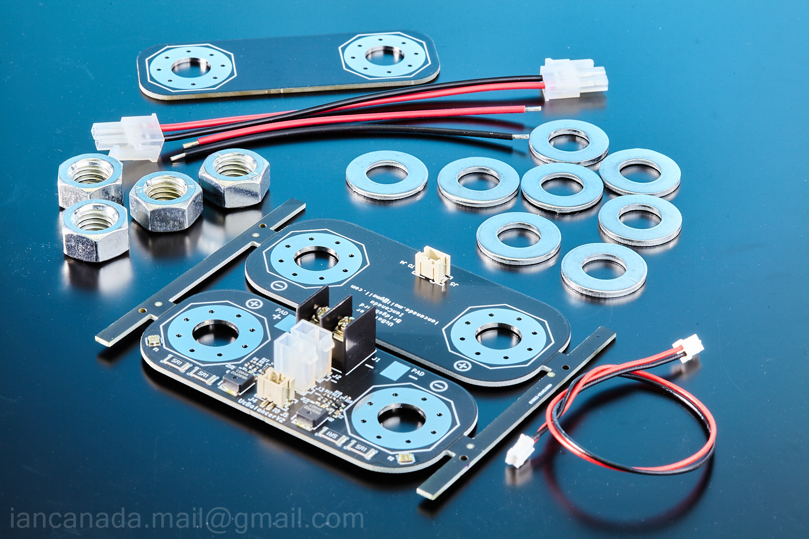
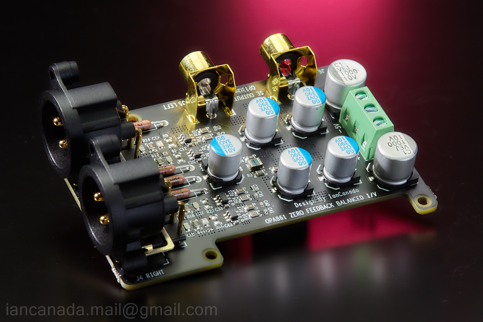
 GB2023 by Ian
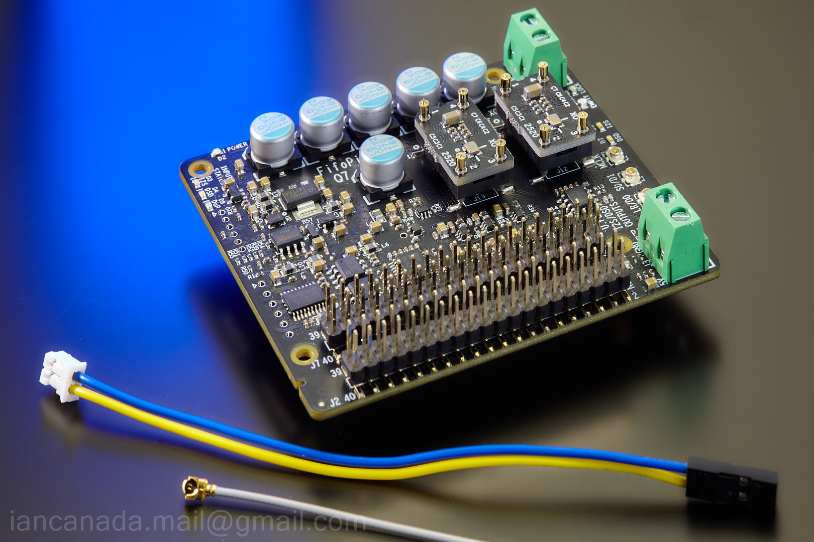


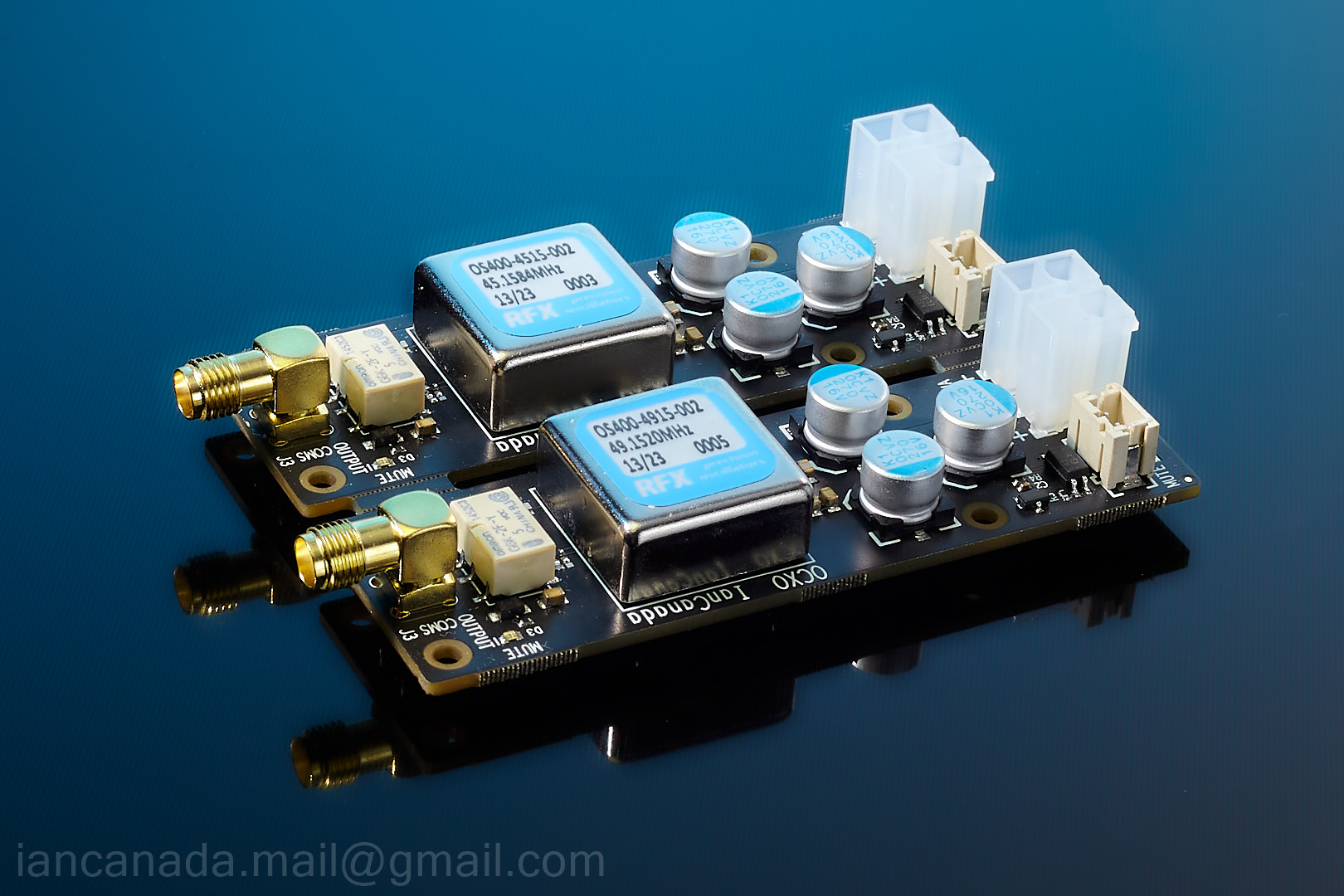


 ES9038Q2MDMII by Ian
 ReceiverPiDDC by Ian


