JBL LE8 pair

SOLD
One pair of JBL LE8 driver. These are the rare original 16 ohm version with Alnico magnet (not the later LE8-T or LE8-TH). These were reconed by JBL a while back and have just have new foam surround installed. Serial numbers are 13359 and 13363, so they were bought at the same time. Still have the JBL box that was used when returned from recone. Ship from US 94022.
Note that there are some very slight dent on one of the metal dust cap. It doesn't show up well in picture. One of the black plastic cap is missing from a terminal (as shown in picture). Does not affect functionality,
Please PM with offer and ZIP code (for shipping quote) if interested.
IMG_8512.jpeg
IMG_8513.jpeg
IMG_8514.jpeg

Circuit design for EMI immunity

I took the chance to make an opening thread. 😀

There are almost no examples of amplifier or preamplifier design using this option. I have experience with two designs so far.

Zero Signal Planes are PCB copper pours, which are connected to the ground at a single point. That way, there are no loop areas which could add EMI induced noise to the signal. Only downsides are that you have to use more expensive 4-layer PCB and there will be higher parasitic capacitances between signal tracks and ground.

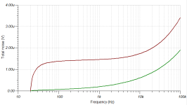
Here is an example of output noise from my latest amplifier (measured with calibrated LNA), that will be published here in a week or so. Mains transformers are some 10 cm apart from the signal tracks, yet induced 50 Hz noise is only 700 nV.

Output noise.png

Why is DC offset very high when cold?

Hello,

I trying repair an amplifier

Problem is treble amp offset reads -32 VOLTS when COLD!!

amps bias is fine

- When amp heats up dc offset drops to +- 50mv, this is withing manufacturers specs

- Dc offset bounces a lot when hot, from 50mv to 10mv then to 70mv and back to 50mv

Bias is stable when hot

Manufacturer specifies that amp should be measured hot

- when this amp is working normally, offset is max 200mv when cold. I have excatly the same amps which work normally

- offset trimmer pot is tested and ok

- the whole amp board was resoldered just in case, looking for bad connection, no changes

- When amp is hot and its turned off for a couple of seconds, DC offset is immediately -5.00 Volts from -50mv. And starts super slowly rising back to 50mv

What are the main causes for DC offset to be so high when cold?

Attachments

  • 20230906_153503.jpg
    20230906_153503.jpg
    180.1 KB · Views: 158

Capacitor multiplier with multiple pass elements?

Hello everyone, is there any reason I couldn’t have a capacitor multiplier with multiple pass elements?

I’m in the early stages of designing a power supply for an amp i’m working on where the B+ can be adjusted. I was designing one with one B+ output for both channels, but now i’m wondering if I can get better channel isolation by "slapping on" another pass element running off the same driver, since the pass elements have high impedance inputs.

DD20F25B-5720-494C-801A-192DC14AD15B.jpeg


I could run two separate circuits off the main filter cap but then I would have two voltage pots which I prefer to avoid.

Speaker isolation for hardwood floors that allows for easy adjustments

Hi, I just built large, bulky speakers that need to be away from the walls for listening and closer to the walls when not in use. Need something that will be kind to recently refinished oak floors. Wondering if a full layer of wool felt might be good. But maybe spreading out the footprint is bad and a four foot approach would be best. Any thoughts? Unless it matters I am looking for a less expensive fix. No esoteric $300 speaker feet. I read about people using cut up wool dryer balls. What is the most sensible and effective approach?

Attachments

  • IMG_20230926_171902.jpg
    IMG_20230926_171902.jpg
    166.2 KB · Views: 96
  • IMG_20230926_171908.jpg
    IMG_20230926_171908.jpg
    266.8 KB · Views: 99

Studio Series Headphone Amplifier construction thread

Hello forum members hope all is well
I know there are numerous headphone amplifier designs (very nice ones in the DIY audio store) plus I am a big fan of the JLH single ended Class A design but I have become very fond of this design and the PCB layout (no surface mount and big solder pads for us oldies)
Also to my ears sounds very nice, I have decided to make a test bed for tweaks and document on this wonderful forum

I decided to make my 1st module with good quality budget components with a few notes below

1. The op amp is a OPA2134 ( I have used an OPA2134 audio op amp here for best budget performance) but will try other op amps once completed
2. Matched all the transistors 1st time I have done this
3. Used Jantzen output inductors ( from HiFi collective UK based online company ) 0.005mH Jantzen Air Core Wire Coil AWG20, 0.8mm diameter wire
4. Cardas`s quad eutectic solder in the build

I think this is a very good sounding headphone amplifier sure there are better designs but thought its worth a mention and would be fun to see once built how it compares with other designs

Spec Below

Attachments

  • 1692367209703.png
    1692367209703.png
    29.7 KB · Views: 210

Sound advice needed on operating systems and security software

I've taken delivery of a new mini PC which comes loaded with Windows 10. I don't like the way that Microsoft is always trying to sell me something. I've also had my Hotmail account hacked from 3 different countries - Russia/USA and the UK - I live in France. Luckily I hav'nt suffered any financial problems.

I did for a few years have a secondhand PC using a Linux system (I can't remember which one now) It was lovely not being bombarded with sales pitches but when I had a problem it was difficult to find anyone here in France where I live to sort out the problem, apparently in France only 1% use Linux. I would seriously consider Linux again BUT I only want a KISS system not one loaded with programmes I'm never going to use.

Unlike many I live a very simple online life - I have absolutely no need for social media of any kind. I don't live my life online. I use the net for nec. communication - tax/health/buying/selling and bookmarking info, one of the very real benefits of the net. I don't stream music because I have virtually everything I need. I should by Christmas be able to start digitising my collection of LPs/CDs and offload all that gear leaving me with a couple of mini PCs, one dedicated to stored music just using h/phones. Seriously thinking of living in a motorhome rather than building a house. Stripped down but comfortable living and moving around Europe.

Re. online security I've managed after lots of hassle to free myself from Avast - always trying to sell me something else, if I bought into all their subscriptions it would have cost me hundreds of Euros per year. This company even had the cheek to take another year's subscription just short of 5 weeks in advance. I would really appreciate sound advice on good online security software, paying is not a problem but no more constant hassling to buy.

The mini PC is a Pantera Pico
Intel J4125 Quad Core 2.3GHz CPU
Dual-band WiFi 2.4GHz/5GHz 422 Mbps
512G SSD
8GB LPDDR4
3xUSB 3.0 / 1x USB 2.0
HDM12.0 port
audio jack
m.2 SSD + MicroSD Expansion slot

My existing mini PC will be used only to store my music kept permanently powered on, important when using SSD and when I have downloaded the software to record the music will not be connected to the net.

I use Yahoo as primary email (had no problems) I don't like Hotmail, I also have a Gmail account, I'd prefer to use that as back-up instead of Hotmail.

What Linux KISS programme should I consider and what online security software, very grateful for all sensible answers.

For Sale FS Raspi - 4137 Hat board i2S signal relocker

purchased this to use with my Streaming Dac based on the protodac TDA1387 in hopes of a better clocked i2S. I ultimately preferred the Hifiberry Digi2 Pro inbetween the PI and the protodac cleaning up the timing and Jitter. Its essentially new. Uses the AKM Chip 4137EQ

25 shipped Cont USA or entertain trades for a Kali reclocker or Ian variety reclockers and cash on my end. Let me know.

Attachments

  • IMG_9729.JPG
    IMG_9729.JPG
    529.4 KB · Views: 70

Tektronix 2430A lost cal data / repair

Well the other day my beloved trusty Tektronix 2430A greeted me with a self test fail. 🙁 Of course this always happens in at the most inopportune moment, as usual.😀
I am sure others have seen this issue before me. I am trying to describe what I did try to get the scope back to working order, perhaps this may help someone who is facing the same issue. As it turns out the very special NVRAM chips have finally lost battery charge and corrupted the cal data checksum. The offending chips are U664 (Cal Data) and U350 (Waveform Data). Both chips in my scope were Dallas DS1235ABW-120 vintage 1990. I would not want to complain as these chips kept data much longer than what they were spec'ed at. 🙂 I found some old new stock on ebay with a fairly 'recent' mfg date and bought some. Despite the corrupted data in these chips, I decided that I may have nothing to loose if I tried to read these chips in a programmer and perhaps pre-load the replacement chips with whatever I can read out of the old ones and perhaps reduce any calibration efforts. As I did not have a programmer, I turned to ebay and bought a cheap one Model TL866CS. I removed the main-board for convenient access as the offending chips were not on sockets and needed to be unsoldered, I installed sockets for the new chips and would recommend that. The old chips still contained some data got loaded into the new chips without problems. Then the pre-loaded chips were installed on the sockets and the main-board was installed and reconnected.

Then as part of the calibration procedure, jumper J156 must be removed to enable extended calibration feature. After successful calibration this jumper should be put back.

I believe I read that it is advisable to operate the scope only with installed case as the air flow is as ist should be, otherwise if the scope is operated without the case in place it may not have sufficient airflow and some chips could die due to overheating.

The calibration is very easy, one needs a decent variable lab power supply that can provide up to 20.0V, A few BNC cables and adapters may come in handy also.

With the enabled calibration features and warmed up scope

Initiate EXT CAL

Run ATTN cal, and follow on scope screen instructions.

Run SELF CAL and turn off scope and turn back on.

Run TRIG cal, and follow on scope screen instructions.

and turn off scope and turn back on.

Run REPET cal.

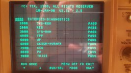
Run SELF DIAG to confirm the errors were cleared and the scope now passes self test.

If needed repeat calibration as per above.

This should clear the following self test errors

3000 SYS RAM
4000 FPP
6000 CHECKSUM-NVRAM
7000 CCD
8000 PA
9000 TRIGS

Now, I am a happy camper again 😀😀😀
:cheers:

I like my Tek Scope and hope it will remain in service for a very long time.

Attachments

  • Resized_20170722_212451.jpg
    Resized_20170722_212451.jpg
    164.6 KB · Views: 858
  • Resized_20170722_212556.jpg
    Resized_20170722_212556.jpg
    154.7 KB · Views: 699
  • Resized_20170722_212617.jpg
    Resized_20170722_212617.jpg
    151.8 KB · Views: 682
  • Resized_20170722_212635.jpg
    Resized_20170722_212635.jpg
    141.4 KB · Views: 699
  • Resized_20170722_212653.jpg
    Resized_20170722_212653.jpg
    170.8 KB · Views: 754
  • Resized_20170722_212711.jpg
    Resized_20170722_212711.jpg
    158.3 KB · Views: 538
  • Resized_20170723_192551.jpg
    Resized_20170723_192551.jpg
    198.5 KB · Views: 559
  • Resized_20170723_192912.jpg
    Resized_20170723_192912.jpg
    161.5 KB · Views: 575
  • Resized_20170929_201056.jpg
    Resized_20170929_201056.jpg
    132.3 KB · Views: 525
  • Resized_20170929_215234.jpg
    Resized_20170929_215234.jpg
    162 KB · Views: 612

Visiting an old friend

In 1980 I built the Maplin lateral mosfet amplifier.
This was based on a Hitachi datasheet lateral mosfet amplifier schematic.
It worked well.

A few years back I decided to see if I could modify it to use irfp240/9240.
So designed a new pcb with new outputs.
I added a dc offset pot, Vbe multipler and decoupling of front end to reduce hum.
Not a bad sounding amplifier.
2409240.JPG

D220Ti vs. DE250 Tone Burst showdown

Both compression drivers above are arguably the most popular for DIYers. D220Ti is the darling of Econowave, and DE250 is used extensively in Gedlee Speakers.

Having built the Econowave I wanted to get that "extra smoothness" so popularised by DE250 reviews. After finding out that they had good polar response with Econowave, I bought a pair and lived with it for a while. Indeed they sounded very smooth.........But after a while I thought D220Ti is more resolving and DE250 is too "mellow" ?

Anyway after multiple swap between these two drivers I decided to test them using tone burst (because distortion test is boring and DE250 won the CSD.. he..he..). Read about Tone Burst test here.

mvYxF.png


SO the key summary:

1.5khz - 6khz: DRAW, they are practically the same although DE250 had small win. But not enough to differentiate at all.

6.5khz - 8.5khz: Winner: D220Ti. DE250 is having a hard time to return to zero amplitude. I think this is a major factor why D220Ti sounded more resolving (being metal?). At 7.5khz the DE250 output is quite deformed.

9k - 13k: DRAW
, D220Ti a bit better

14k - 15k: Winner: DE250 by miles D220Ti falling apart at 15khz

16k - 20k: Winner: D220Ti picked up and left DE250 behind. The tests were not audible to my ears anymore.


So the conclusion is D220Ti performs better in Tone Burst test. The test itself could be improved by less increments of frequencies to cover more differences but this one should be enough.

D220 is confirmed to be more resolving, and while DE250 is smoother it is at the expense of resolution and accuracy.

The good news is D220Ti is much cheaper. The bad news is ... I've invested in the DE250s

🙂

Attachments

Popping noise at turn on

When first turning on my IRS2092S amp, it's fine. After turning off the amp and back on within 30 seconds or so (with volume up), there's a popping noise. This sometimes causes pulsating popping noises. When turned on with the volume down, there's no popping noise.
I do have a 100mfd non polarized capacitor from the output of the volume control to the input of the amp.
Any way to avoid the popping with the volume up?

AIYIMA A03 - TPA3116 D2

I owned an AIYIMA A03 amp below.
https://vi.aliexpress.com/item/1005004563887441.html?gatewayAdapt=glo2vnm

It will be great that it can produce more BASS than this from its Left & Right channels (not from subwoofer out). Is there anyway I can get some more bass from it?

My speakers are Two Way 5" Phillips speakers & supply voltage is 19V, Signal from Phone Bluetooth.

Thanks

A2760 help

Hi all

I’ve got an old school DSE A2760.
I decided to remove the pre-amp module and make a few mods following the guide here.

https://www.overclockers.com.au/wiki/DSE_A2760_Amplifier_Modification

Now that I have put everything back together I’m actually getting no audio output 😭

Looking for support on what I should be checking to fault find. I have checked across the whole underside of the board. Nothing looks suspect.
Amp powers on fine. Only volume control I’m using is via the PC and verified input cabling is fine.
I can actually hear audio but it’s very very quiet. Ramping the volume on the pc makes no improvement.

First Crossover design: Xsim questions

Hi,

I am designing my first crossover using Xsim. I am using Scan-speak D2904/710002 and 18W/4531G00 for a 2-way bookself. Both drivers are 4 ohms.

I notice that the impedance of the midwoofer drop lower to 2 ohms after my crossover. I know that it would be hard for the amplifier, but the impedance is smoother without that two humps.

Would this be a good design? What would you improve?

Here is the impedance graph and design
2.png
1.png

For Sale ACA amp and ACA pre HP amp

Hi there,

I built these at the beginning of the year. I used them for tests and no need anymore.

The amp comes with the original DIY audio store switching supply. Works great.
I am asking $150. Original cost was over $300.

The preamp/HP amp is built in a Galaxy chassis and has Alps pot and linear power supply.
I am asking $150. Original cost for the kit, chassis, power supply and other parts and connectors was over $300.

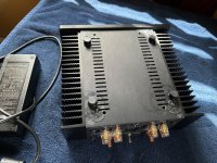
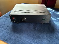
Hope these will find a good home. Pictures show few imperfections:
-the amp bottom has extra holes and traces of a different feet style
-the preamp front plate near the main switch has punching marks from the back of it.


Thanks for looking,
Radu

Attachments

  • IMG_9411.jpg
    IMG_9411.jpg
    678.6 KB · Views: 129
  • IMG_9412.jpg
    IMG_9412.jpg
    695.4 KB · Views: 107
  • IMG_9413.jpg
    IMG_9413.jpg
    710.9 KB · Views: 106
  • IMG_9414.jpg
    IMG_9414.jpg
    661.1 KB · Views: 108
  • IMG_9416.jpg
    IMG_9416.jpg
    738.4 KB · Views: 113
  • IMG_9417.jpg
    IMG_9417.jpg
    727.8 KB · Views: 103
  • IMG_9418.jpg
    IMG_9418.jpg
    709.9 KB · Views: 101
  • IMG_9419.jpg
    IMG_9419.jpg
    666.9 KB · Views: 125
  • IMG_9420.jpg
    IMG_9420.jpg
    553.8 KB · Views: 128

Yamaha NS-6HX modification

I was debating with myself if this would be worth posting or not, but here it goes..
I bought these for cheap to use as garage speakers. A pretty solid 3-way with 8" woofer, 5" (?) mid, and a 1" alu dome tweeter. Tweeter and mid are in a alu waveguide.
Cabinet is pretty well constructed, Xo is 'old school' 2nd order using some electrolytics and some poly caps, and one iron core coil for woofer. Drivers seem pretty sturdy too, with some white hard paper cones and alu baskets.
They sounded ok as tey were, but I wanted to play around with them a bit and see if I could improve the sound a bit, and it seems I could.

The cones were yellow, so I started with some paint to make them white again.

Woofer XO: Notched a pretty bad cone resonance at 3k, so I notched it with a R+C parallel to the inductor. The LP was also high Q, so I damped it a bit with a resistor in series with the cap. There was also a bump in the response around 100Hz from the coil and woofer impedance combination, so I added a impedance smoothing circuit to tame the upper impedance peak of the woofer.

The mid had a bad 'wrinkle' in the response around 2k, abt 5dB from peak to dip. I figured it was a classic cone-surround issue, so I put some Mod Podge in the area. It improved it to abt 2dB, and I left it at that. The HP was high Q and not well phase aligned to the woofer, so to make them work together better, I used a high value resistor in parallel with the HP cap. I have seen Troels do this on some projects, and this is the first time I tried it with good results. LP for the mid was also high Q, and I grounded the LP cap through a low value resistor to tame it. The level of the mid was boosted in the stock speaker, so I figured I would try a series resistor on the mid to bring the level down, and also reduce distortion. I measured distortion with and without the resistor, and it made a significant difference, 5dB distortion reduction from memory. The increased impedance seen by the mid around resonance worried me a bit. I stuffed the mid enclosure full with sheep wool to damp it a bit, and it sounds ok to my ears.
Again I added a notch to tame some cone resonances out of band (6-7k).

Tweeter: I had to change from 2nd to 3rd order (electrical) to align the phase of the tweeter to the mid (only changed cap value and added a large cap. Also a small resistor before the XO to give the FR a gentle downwards slope as I like it. I did not bother to put the resistor on the tweeter side, since tweeter distortion was way lower in level than mid anyway. I figured I would prioritize the load on the amp in this region, since the impedance was a bit tricky here because of the original filter design.

I kept the same XO points, since I did not want to redesign the complete XO and buy new components. This is why I did not bother to take complete off-axis measurements, but stayed with only the on axis.
FR is a lot flatter than before, and measured distortion lower in the midrange. Subjectively I got tighter bass, better woofer/mid integration, so voices and drums sound better and clearer. Mid sounds more pleasing and smoother. Can't say I hear much change in the treble area, possibly some more 'depth' in the sound stage up there.

Before and after:

1696256149273.png

1696257667616.png


Every time I have done the impedance flattening on woofers with fairly low XO, I have been amazed with how it subjectively improves the bass, so I decided it was worth doing, since I had the components from another project. It was also interesting to move towards 'high impedance drive' ( don't dare to call it current drive) on the mid, also a subjective improvement.
I also added an oak brace between side walls below the woofer, it did not pass the knock test.

received_196268970150571.jpeg

Substitution for "1000pf 680v syrene" capacitor?

I am preparing to do the RFI modification for my Audio Research SP-10 preamp (see attached). The instructions call for 1000pf 1kV ceramic disc capacitors to be installed between all power supply output lines and ground, except for B+, for which they specify a 1000pf 680v syrene capacitor. This leads me to a couple of questions:

1. Does "Syrene" mean "polystyrene"?
2. Mouser only has 1000pf polystyrene capacitors up to 500v. Can I substitute a different cap type here?

Attachments

  • ARC_SP10_rfi.jpg
    ARC_SP10_rfi.jpg
    137.1 KB · Views: 82

Retreading the Motown Sound: Best Restoration Software Tools?

I have loads of Motown favorites, such as this gem which has been playing in my head all week. Login to view embedded media
Tony Thompson well describes here the causes and reasons for, shall we say, the less than ideal sound quality of many otherwise wonderfully arranged Motown recordings.
https://www.quora.com/Why-does-it-s...her-recordings-from-the-era-well-into-the-70s

Thanks to Mr. Gordy's aggressive techniques for marketing his music products, there's presumably nothing than can be done to "decompress" many of these tracks. But besides removal of some overload (clipping) distortion, where it may arise, https://www.izotope.com/en/learn/repairing-a-distorted-audio-track.html and flipping stereo channels to be in-phase with each other, which if any other sonic damage might Izotope Rx or other software tools be able to reduce?

What was the FIRST album you listened to?

We have a thread "Last Album Listened To..." what was your first.

Me -- "Mickey Mouse's Birthday Party" probably around 1955. (I have mentioned elsewhere that I found you could listen to the album with a paper cone and a pin stuck to hold the cone together a la Edison).

First stereo recording I recall hearing as an album was Anna Moffo "Arias from Faust, Gounod.." circa 1963. It was on my uncle's KLH "portable" headphone player. I still have that recording.

Beyma TPL-75 AMT & Frank Sinatra

Thanks to whoever it was who suggested the Beyma AMT, it is the real deal.

<iframe width="560" height="315" src=" Login to view embedded media " title="YouTube video player" frameborder="0" allow="accelerometer; autoplay; clipboard-write; encrypted-media; gyroscope; picture-in-picture; web-share" allowfullscreen></iframe>

I replaced the Fountek NeoCD3.0 ribbon tweeter in a previous prototype (with a Bold North Audio BNA 4001 4-inch carbon-fiber woofer) with Beyma's TPL-75 Pleated-Diaphragm Tweeter, also known as an Air Motion Transformer (AMT).

There was a lot more of Sinatra's voice coming out of the tweeter than I expected.

The cabinet maker will start work on a new front panel for a larger, in-progress cabinet next week.

Also, there has to be a new crossover.

I think we are on a good track, so Thanks again.

john

CAB DESIGN or looks are everything :)

Hello over there round the globe!

Our beloved hobby needs some boosting so I thought why not copying existent designs to please our eyes if budget is too low for Accuton , Mundorf and the likes ... instead of using expensive large-size ribbons , AMT's or other cost no object stuff you can replace them with the PT6816 from PE/Dayton Audio , lots pictures at the bottom :

https://audaphon-com.translate.goog..._sl=de&_x_tr_tl=en&_x_tr_hl=de&_x_tr_pto=wapp

More stuff to feed your eyes :

https://audaphon-com.translate.goog..._sl=de&_x_tr_tl=en&_x_tr_hl=de&_x_tr_pto=wapp

The combination of white cab and light-gray sub-baffle without distracting screws on the front makes this design so special , and the slim rectangle tweeter gives some hi-tec appearence!

Hard to beat!

have a nice DIY time!
  • Thank You
Reactions: GM

Help with fusion amps

Hi all,

I just bought 2 Fusion FA123 amps but I'm having trouble with a couple of things.

1. When I attach each unit to my laptop via USB, one of the units is correctly recognised as productcode: FA123, firmware is 1.51 and DSP filename is New Project. But the other unit reads, productcode "unknown", firmware is 5.4 and DSP filename contains no data (i.e. field is blank).
Any idea what could be going on here?

Judging by the firmware versions, I'm guessing I have one older model with IIR filters only and one newer model with both IIR and FIR filter capability.
But why the 5.4 unit won't be correctly recognised FA123 is a mystery. I've power cycled the units etc with no luck.

2. My next problem is trying to configure the two amps for my 3-way active setup. I'm pretty tech-savvy but the manual and software sure lives up to reputation...a bit tricky to use.

If anyone out there could give me a quick how-to that would be really appreciated.

I have all the correct cables. I have one coax connected to the s/pdif out of my USB sound device ---> s/pdif in on the first unit. Then I have a second coax connected to the s/pdif out of the first unit --> s/pdif in on the second unit. I also have the correct USB 2.0 cable for filter configuration.

Many thanks in advance.

Weller Soldering Tips Problem

I recently bought a cheap Weller pencil iron as a spare: model SP40N 40W which uses ST series tips. A terrible product, the LEDs are the old basic clear ones that provide practically no illumination, the iron is no better than a 10 euro iron from the craft shop, maybe worse. I’m having trouble with the tips (original Weller) and after 10 minutes use I've already trashed two. For the first tip I did what I've been doing for 30 years, wipe the tip clean on a damp sponge between uses. For the 2nd tip I used a brass wool ball thing instead. Both times the tip oxidized and got reduced to rough bare metal after 10 minutes and could no longer be tinned. Beats me I’ve never come across anything like it.

Maybe the iron is a bootleg Weller with crap tips but that’s unlikely. I’m using leaded solder and wondering maybe if the current tips can’t handle leaded solder or maybe it’s the flux used in it, solder is tried and true Kester 44. I’m flummoxed and have one tip left before I throw the whole iron in the trash. I always found Weller super reliable and got plenty of mileage out of their tips in the past using their soldering stations.

Maybe someone here has had a similar problem and can say if Weller's gone to crap, or a faulty batch of tips, or the lead solder?

NOOB QWTL concept. Tell me why it won't work and what to simulate it with

So I went and bought the DIY Perks plans for those QWTL speakers he made. I have access to a great 3d printer in work which means I can do insanely long prints like these.

Got most of the way through printing one when I thought, "This doesn't really take advantage of a 3D printer does it"

So here's my concept for a QWTL that would need to be 3D printed I might test with these little tangband woofers.

After the first fold the transmission line is annular. In this model the cross sectional area of the TL is maintained constant with each fold.

Anyway, I'm a noob, so before I spend a bunch on filament to print this thing, it'd be great if someone can tell me why this won't work. Are there particular considerations for annular ports? what do they do to sound?

Also if someone knows what software might be best for simulating a shape like this I'd be much obliged. Could hornresp do a useful job in a case like this?

Screenshot 2023-10-05 at 22.12.13.png

Frankenstein Magnavox CDB582

I posted an AK also....

Bought this today at an estate sale with a bunch of DVD players. Check out all the capacitors added around TDA1541A and about the whole component board. There is a cable soldered in also. The problem is that it won't play music when I connect it to my amps through the RCA outputs.. Tried 2 different tube amps. I can hear what sounds like the CD spinning through the speakers, but no music comes out. The timer counts and it looks like everything is working. I have it plugged directly into the amp, so it should be playing at 100% volume. I don't have a remote. Can't wait to take the cover off the DVD players. 🙂
thumbnail_IMG_2590.jpg
thumbnail_IMG_2591.jpg

Summing wires

I’ve been doing some research into how to convert a stereo signal into a mono signal as I want to connect my decks (stereo rca out) or laptop (trs out) to my amplifier in bridged mode via xlr as this seems to be the easiest connector to hide the resistors. I’ve seen lots of different videos all suggesting seemingly randomised values for resistors, some saying you need to link the unused terminals on the xlr end and some not. Has anyone got any experience making cables like this and would be able to provide more clarity on how to do so

Can you improve these amplifiers?

I am currently trying to design an amplifier for the output of a generator. It needs to work at up to 1MHz, and have a negligible distortion, ideally in the ppm range whilst delivering 30 to 40Vpp.
This is my first tentative:

1687425104742.png

The THD is ~0.01% and there are cheats: spice sources used as ideal buffers, because the base currents of the transistors are too large and too distorted. Additional transistors would be required.
There is also a nasty, unexplained peak in the frequency response, in the region of 200MHz.

Attachments

towards a vanishly low distortion crossover

I am working on an input stage to marry with my latest speaker design (12P80ND + HF10AK).

Here is the input stage thus far.

Simple balanced instrumentation front-end, high-pass filter for subsonic filtering, and a shelving low-pass filter.

The signal chain may be quite long after the buffer downstream to the woofer and the cd.

I'd like to maintain a transparent signal, if at all possible.

Attached v1 of the TinaTi.

1696583318028.png

1696583700889.png 1696583816974.png 1696583777990.png

Attachments

Transtec Transformer TT0869803320-E

Hello,
I am Kathir from India.
I have JBL SCS 140BK230 Digital cinema speaker system.In that My Active sub woofer has stopped.due to No secondary output from transformer and No output details mentioned.It has 5 wires in secondary other Transformer Details Transtec Transformer TT0869803320-E.
Service manual checked No secodary AC volt output data.but in service manual circuit diagram end termination shows only DC details +15V,-15V,0V,+VCC &-VCC.
I have no idea about +VC,-VCC and amp ratings.
Circuit and Transformer derails attached.
It may be thermal fuse or transformer.
If anybody having the replacement or five wires secondary output ,I request pl be post it.

SSE - Choke DCR?

I'm creating my shopping list for magnetics, comparing options and prices. For the choke I have been looking at values in the range of 5-6H with 200-250mA current capability but I have no idea what DCR value is recommended. I searched here but didn't turn up a direct answer.

Should the choke DCR be approximately equal to R1 that it replaces (150R)? Is there a significant effect if DCR is lower or higher than C1?

20N20 availability

Hi there

I'm trying to find out if there is any availability of the Exicon 20N20s anywhere (ideally in Australia.) I heard they are discontinued. If yes, where? Would I only find second-hand ones? Would these be acceptable to use? If not, is there an alternative that would suit my beloved power amp that started smoking a while back? Refer images.

The amp in question is a British made Matrix 1300W amp. I used it for many years and it always hade a great sound, with plenty of grunt.


Or am I best just laying it to rest?

I'm hoping to use the amp to rive some passive subs for my band.

Cheers

Attachments

  • 20N20-1.jpg
    20N20-1.jpg
    298.7 KB · Views: 115
  • 20N20-2.jpg
    20N20-2.jpg
    338.4 KB · Views: 120

Ebay: 500W +/-70V PSU Audio Amp High-power

Hi, I bought this power supply form eBay. I blow it up with a short on the output. I replaced 2 FET transistors blown, and the back 0.1ohm R, but is not enough. Looks like the no-name black module between the caps and transistors is busted too.

404 Not Found

Is molded in epoxy and smashing it I could not figure the schematics.

Would be great appreciated s schematic for such Chinese power supply.

Thank you

Live level active XO sought

Can anyone recommend a an analogue line level crossover with delay for the tweeter and baffle step as well as the crossover? Balanced or not.

Ideally as capable as: https://www.ti.com/lit/ug/tidu035/tidu035.pdf
Additional linkwitz transform capability optional.

Failing that, 'stand alone' PCBs/completed for adjustable baffle step and delay would be OK. There's plenty of choice in raw crossover after all.

What happened to the 'zoom' function in Vituixcad?

On the previous versions of Vituixcad, eg V 2.0.97.1, you could change the scale (zoom in/out) in the graph window by pressing the Ctrl key and then scrolling up or down with the mouse.

The only thing that happens when you do this now is that the size of the graph window changes, but the scale remains the same.

In the manual you can read...
'Picture can be zoomed in/out with Ctrl + mouse wheel'.
However, this doesn't seem to work anymore.

Is the ability to zoom taken away, or am I missing something? Anyone who knows?

Passive Radiator Newbie Q?

I'm thinking about using a passive radiator in a new design rather than a port. I have a lot of experience building ports but never used a PR! One main question - do PRs have unwanted resonances above FS in a similar way ports might have a pipe resonance or let internal cabinet resonances escape? How well do they suppress the unwanted garbage?

I guess it would be important not to excite it where cone resonance kicks in, which would be easy in this case.

crackling aftermarket car speakers

The standard configuration in my car is 2x woofers in the front and 2x woofers in the back. There are also separate tweeters, but it doesn't matter, I won't touch them.
The woofers in the back are blown and in their place I connected BOSE mid-range speakers, which are quite bad to hear (buzzing, crackling... as soon as the volume reaches 45%)

Can I insert only woofers in that place or is there some way to leave these mid range speakers? Im guessing that the car sends low frequencies and they are made for medium. How to solve that?

When I connect the BOSE midrange speakers to my ONKYO mini stereo, everything sounds as it should...

Fosgate 500x bias issue

While waiting for parts in the 600.4 I decided to dig into this.

500x, pc-3084c.

Supposedly no sound on 2 channels but they all work fine. Maybe just the fact that it was in 4 channel mode? Rcas aren’t broke.

Idled at 2amps which seemed high. It only has one pair of output fets per channel. Turned all bias pots ccw. Channel 1 seemed to have a much lower setting then the others.

Channels 2-3-4 adjusted as expected. Channel 1 behaves as some have noted here before… voltage across source stays at zero then suddenly jumps at the pot position you’d expect it to be left at. Idle current jumps 30ma and source res voltage goes to about 3-4mv. Turning ccw causes it to go up to about 7mv before it starts coming back down.

Found this thread. Yep that channel is oscillating even after returning to full ccw and will only stop after resetting remote. No input. Once it starts oscillating and you turn pot ccw frequency drops.

Jumping front/back rca shields doesn’t make difference in oscillating but it does drop idle current about 200ma after reset with pots fully ccw

I want to try the mpsa42/92 Perry suggested first but in case that doesn’t work out …. What are the feedback cap designations for this board to experiment with? I couldn’t find a 3084 schematic and the 3085 board looks different enough that I probably shouldn’t use as a reference

Western Electric New 300B made in USA 2018

Western Electric tubes factory is come back with 300B maybe the other tubes in the future as well let's dream.

Official prices per matched pair was 1299 $ after price update pair cost 1499 $ and single tube was 599 $ today price is 699 $

Probably available December 2018 :clock: in time for its 80th Anniversary.

300B — Western Electric - Maker of electron tubes and high fidelity

Western Electric- YouTube

Western Electric - Official Home Page

Library — Western Electric - Maker of electron tubes and high fidelity

https://static1.squarespace.com/sta...3/000+Vacuum+Tube+Title_Index_Information.pdf

Enjoy :cheerful:

Attachments

  • F50DC0B8-62E0-4EED-A377-5FB06EB5AC32.JPG
    F50DC0B8-62E0-4EED-A377-5FB06EB5AC32.JPG
    162.9 KB · Views: 3,961
  • 604A9D51-D6F6-4BBC-ABB6-3544A7373EE0.JPG
    604A9D51-D6F6-4BBC-ABB6-3544A7373EE0.JPG
    522.5 KB · Views: 3,774
  • 76D6AA5F-A7CD-46A6-A85F-33A42826B29A.JPG
    76D6AA5F-A7CD-46A6-A85F-33A42826B29A.JPG
    348 KB · Views: 3,674
  • 86B44285-8585-4598-B346-AD824DFBA29E.JPG
    86B44285-8585-4598-B346-AD824DFBA29E.JPG
    289.6 KB · Views: 3,574

Installing LinearX LEAP 5 on 64-bit Windows 7 / Windows 10

With Chris Strahm's passing, there seems little hope that LEAP will be upgraded to support 64-bit platforms.

I have LEAP working on 64-bit Windows 10 -- dongle driver installed, software install errors worked around, etc. (It's far less complicated than on 64-bit Windows 7.) I've written up instructions and need a few folk to help test before I share the instructions more widely.

If you have LEAP and 64-bit Windows 10 and are willing to test the instructions, please send me a PM stating your version of Windows 10. (If you're interested but not willing to test, please post a message of encouragement.)

Thanks.

JL Sounds I2SoverUSB viii locked to 48khz sample

Hey folks, I am running a JL Sounds I2SoverUSB vii into an AD1862 configured like the JL manual instructs. This works fine with standard Windows 11 drivers and with the supplied JL Sounds drivers available on their site.

With either Windows 11 drivers or JL Sounds drivers, the unit is locked into either 44.1 or 48khz sample rate. When I am playing 96khz files, it downsamples to 48khz.

Does anyone know why this is? I can't find any option in the JL Sounds driver software to change this. I'm a little confused, what should I be looking at?

Luxman L308 refurb: technical questions for main amps.

Hi all,

Refurbishing an old defective Luxman 308 amp, I found the main amp boards schematic is like the following (of the l80) and although there may be more, my first questions are:

1. why is the r115 resistor supplying the zener so low (zener gets some 15 milliamps as supply voltage is around 45 and it will run quite warm, as does the resistor). Note, in a newer amp (l85v) they do not not have the r116 470 Ohm but the 1k5 resistor is 8k2 there.....

2. Just drilling 2 little holes, I can bypass the zener with a little cap, would this be beneficial? read: will zener noise affect operation much, here?
Luxman did this in a later mode L85v having same input circuit (although the mentioned 5k6 resistor is 4k7 there)l, they put in a 40 nf ceramic cap.
I presume they just standardized on 40nf caps, as they used this value as ceramic bypass on several positions in different amps. I could put in a nF range ceramic cap, there is not much space for anything else, or a little tantalum electrolytic of a few microfarads, which could fit.


308schema.jpg

B1K Preamp

First off, this is not either of the two units that I was working on as described in the B1K thread. I actually had nothing but success with this one. I really like building these and going with different, sometimes the same look as the one before it. No headphone output here FIY.

Anyway, I built this with yet another 554 cigar box. It does look sweet, Made an oversized power supply for it with good filtering designed by Pete Millett. Mostly, the things that I added are cosmetic, but also it is a heavier unit with the thought vibration control behind it. Note the Pete Millett isolation mount for it. Also, I will point out that there are 2 inputs, each with a different level so as to have more control of source input. One input is about 12db down from the other. Questions welcomed.
$400+ shipping.

Attachments

  • P7270001.JPG
    P7270001.JPG
    468.7 KB · Views: 173
  • P7240012.JPG
    P7240012.JPG
    292.5 KB · Views: 170
  • P7240005.JPG
    P7240005.JPG
    436.1 KB · Views: 169
  • P7240002.JPG
    P7240002.JPG
    755.4 KB · Views: 168
  • P7240008.JPG
    P7240008.JPG
    441.4 KB · Views: 166

For Sale Quant Asylum QA400 Audio Analyser

Due to upgrade the QA400 is now surplus to requirement.

Purchased new the QA400 has served me well and is a good reliable piece of kit and is in top condition.

The loopback test results screen capture are in the last image below.

The QA400 USB front end control software runs directly under Windows XP, Vista and Windows 7.

Windows 10 and 11 require the use of eg. the freeware VMWare Workstation Player to run the QA400 control software, same applies to running the QA400 under Linux.

The QA400 comes in the original box with the original set of loopback BNC-BNC leads, a USB cable and a printed copy of the user manual. The latest Windows drivers will be available for download from my dropbox.

The comprehensive user manual, which details the QA400 large range of test functions and example test scenarios, can be downloaded from here...
https://drive.google.com/file/d/1pfUUaTyY7UthGmwvAENqAqeGdrtr3tyg/view?usp=sharing

Price is £175 including insured shipping in the UK, though sensible offers will be considered, payment via Paypal.

From a pet free and non-smoking household.

QA400 6x4 1.jpg

QA400 6x4 2.jpg


QA400 6x4 3.jpg


QA400 6x4 4.jpg


QA400 6x4 5.jpg


QA400 6x4 6.jpg


QA400 loop back test large.jpg

Attachments

  • QA400 6x4 5.jpg
    QA400 6x4 5.jpg
    519.4 KB · Views: 109
  • QA400 6x4 6.jpg
    QA400 6x4 6.jpg
    519.2 KB · Views: 101

JLH Class A Hart Kit construction thread 1996

Hello folks

Yes yes I know I have many construction threads, but this little project has been on the back burner for some time, while I am waiting for parts for my many other projects I thought I would have ago at making one of these units and see what all the fuss is about. I have a big batch of original Hart (William hart kits) PCB's so will make a stock unit to make sure all works and improve if I can with all the knowledge on this site ... wish me luck, but at least a lot cheaper then my valve amps that I make

forgot to mention this is a Class A mono block power amplifier ... approximately 15w full class A

RF T2500-1BD going into protect with speaker load

Hello

I'm working on a t2500-1bd (not the constant power version). This amp had 2 bad output FETs and a bad PNP at the gate that pulls down the drive signal. After replacing them with used, but good parts (to test) the amp powers up and plays music fine. The issue comes when I turn the volume up with a speaker connected. The amp will seemingly turn off with a brief second and come back on, before the amp turns off it is drawing about 10amps of power, sometimes it is a little bit more/less. When this happens, I see the protect light come on and then turn off when the amp comes back on. I've tried 1ohm and 2ohm speaker configurations with same results.

If I remove the speaker and run the amp with no load, I can drive the amp into clipping (about 200 volts peak-peak) without any issues. The HV rail test point is reading about 108-110V at idle. With a speaker connected and playing music, it will drop to around 93V before the amp turns off.

The +/-25V rails (RF schematic calls it +LV_CLEAN and -LV_CLEAN), looks stable before the amp turns off as well. Gate drive to power supply FETs look normal until the amp turns off.

DC offset is <50mV

DC voltage at the power input terminals when the amp turns off is no less than 13.20V.

Playing a 40Hz tone with a speaker attached and my oscilloscope looking at the output of the amp. The sine wave looks nice and clean up to the point it turns off.

I think the issue is on the BD power supply card. Maybe some noise is getting onto the protection circuit when high current is present? Anyone have the schematic for the BD PS card? Or potentially know any specific components to check?

I also noticed I sometimes get a slight hum at the speaker with RCAs connected to the amp with no audio playing. Sometimes it goes away.

RPi+DAC+Hypex amps in one case. Who has done this?

I’m researching active crossovers for a possible future build. What I’m looking for is,
  • Raspberry Pi
  • Six+ channel DAC
  • 6x200w amps
All in one case, around the size of an AVR.

It seems doable, but my searching hasn’t provided anything. I’m just looking for ideas on cases, layout, and positioning of components. Trying to fit three Hypex amps and two power supplies while providing enough space for cooling and separation for the DSP seems tricky without getting a large case. Maybe I should befriend some engineers from Denon 😆

edit
I found this earlier in the week which got me looking for similar designs with more powerful amps.
1695421218285.jpeg


https://www.audiosciencereview.com/...to-the-smartcross-project.47976/#post-1721601

First time speaker building - need help with REW + Thiele small signal

I'm working on building a set of bookshelf speakers. I bought two 7" RS180-8 speakers, and just finished setting up REW to measure them. I built the impedence rig myself, and it seemed to work fine.

The one issue (maybe?) is that my parameters are quite a bit off from the published specs. I tested both speakers, and both are similar. But here are some rough deviations:

Left Speaker
Vas 14.85 litres
fs 49.4 Hz
Qts 0.464

Right Speaker
Vas 17.81 litres
fs 45.9 Hz
Qts 0.424

Published:
Vas 24.4 litres
Fs 35.7 Hz
Qts 0.31

Is it normal for the real measured parameters to be so far off? Anything I should look at adjusting?

My resistor measured 98.7 ohms, and I added about 70g of mass to the cone (which might be too much).
The drivers were fresh out of the boxes.
I'm using a USB Scarlet 6i6 sound interface.

Thanks.

Really small enclosure for Peerless

I recently purchased a pair of Peerless PLS-P830985 with which I wanted to make very small speakers for the computer workstation.
I had seen a fairly famous design in Japan:
https://item.rakuten.co.jp/nfjapan/h217/
No information can be found on a possible diy construction on your own, I tried to extrapolate some information but wondered if anyone here has already tried their hand at such a project.
Projects by fanatics, for fanatics
Get answers and advice for everyone wanting to learn the art of audio.
Join the Community
507,384
Members
7,868,015
Messages

Filter

Forum Statistics

Threads
405,277
Messages
7,868,015
Members
507,384
Latest member
RMCO