TDA7850, just for fun

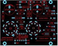
I was curious what was said about the TDA7850, but I didn't like the layout of those cheap kits around.
So I designed my own PCB, fully symmetrical.
PCB size matches the Fischer SK08-100 extrusion heatsink (100x88mm).
And I am using the H version of the chip.

Works first time. No lack of power or bass slamp.
Decent sound for the simplicity. Just for fun.


Cheers,
Patrick

Attachments

  • 220923 TDA7850 Btm.JPG
    220923 TDA7850 Btm.JPG
    186.9 KB · Views: 428
  • 220923 TDA7850 Top.JPG
    220923 TDA7850 Top.JPG
    93.3 KB · Views: 374
  • 220923 TDA7850 Side.JPG
    220923 TDA7850 Side.JPG
    78.7 KB · Views: 387

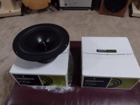
An Amazing Bargain in Powered or Passive Pro Monitors

My review just went up on Positive Feedback Online.

https://positive-feedback.com/reviews/hardware-reviews/solen-monitor-9a/

tT663zdSteL00PMOMTzcjLTMAv1u8AYSqbopRlDQ.jpg


AND: Even if you are not in the market for new loudspeakers, my list of and comments on demo tracks includes a couple of real winners that hardly anyone knows about. Mid-Eastern-style synth music with amazing bass, and some very fetching female vocals!

NB: The Twee-Mid Module on the Solen 9s can rotate 90 degrees, for Horizontal of Vertical orientation of the cabinets.

Not perfect, but... I don't think it can be beat at the price.

all my best,

john
  • Like
Reactions: studiotech

Android EAGLE / KiCAD viewer

Hi all 🙂

Does anyone know of an Android app that can view either EAGLE or KiCAD schematic files? No need to edit, just view. It'd be really useful to have my Galaxy tab propped up on my bench.

PCB viewing can be done via a number of gerber viewers, but I can't find anything for schematics. I know there are web-based schematic viewers, but this approach is clunky IME.

The SSE Gerald R. Ford has finally, uh, sailed

SSE Hot (2).jpg


Just like CVN-78, this SSE was plagued with countless delays and came in far over budget. The problems with getting proper voltage as discussed in the "After a 14 year run, the TSE must DIE!" thread turned out to be the fault of the Hammond 6K7VG I had left over from my first SSE build 15 years ago and since used in several other projects.

Tube complement: Gold Lion 5AR4 and Kt66s, EH 12AT7. Besides the PT the choke is a Hammond 193H and the OPTs Edcor GXSE-10-8.

This is definitely a Winter Amp as the 374BX runs so hot even the top plate becomes too hot to touch after a short while. Sounds great, though, and vewy, vewy, quiet.

Attachments

  • SSE Hot (2).jpg
    SSE Hot (2).jpg
    499.6 KB · Views: 106
  • Like
Reactions: von Ah and sunil

Trim pot values used on Tone Control boards.

So I have this pile of Tone Control and pre amp boards. Purchased from the market.
The objective was to test them all. And hoefully learning something.
My gut feeling is that in many cases the trim pot values used are wrong. I found the orignal schematic for one of the boards. And I noticed that the orignal schematic used a 50K trim pot. But the board I had was using 100K.
In another example. 50K trim pot was used when original design was for 10K.
Is there some quick way to figure out if a wrong trim pot was used in a particular circuit. i.e. setting a bass trim pot to center position should make it sound like no bass is being added or subtracted.
Or by looking at the resistor values used with the opamp. I can predict if the trim pot value is too low or too high.
Or if I need to read up and study on this. How do I approach the subject.

TPA3251 PFFB Gain problem !

Hi all,

I am trying to redesign/make a TPA3251 amplifier with good components.
Most of you must already know that the PFFB approach has better results for all parameters, than a standard configuration according to TI's "slaa778" document.
However,
There seems a problem occours when you use PFFB topology according to this document!
The total gain reduces to 12.75 dB (x4.34) in this case, which is fairly low !
You may say, "so drive it with a pre, or increase the front end stage's gain".
But according to TPA3251's datasheet, maximum input swing is limited to 7Vpp..
So if we apply 7Vpp = 2,48Vrms to inputs then the output power will be just 29W@4R, if you consider the total gain of amplifier.
And this is the limit value, you cannot reach the 2,48v level in any case.
..
So what do you think about that?
Isn't there any way to make a powerfull amplifier with PFFB topology?

Can I use pedal PCBs as line level effects?

Hey, I want to build a rackmount multieffect unit, and mount the jacks, footswitches, and pots to the front of a 19" rack chassis. My question is how can I use pedal pcbs in my effect unit? I want to send line level signals to/from a mixer to the effect unit, but I'm not sure if pedal circuits can accept a line level. Could I modify the pedal circuits to run at line level? Do I need to add a reamp box and di box circuits into the effect unit? Any other ideas?

In stage preamp help

hello, I'm making my preamp, in the input stage I'm using a classic configuration called "instrumentation amplifier" as long as I use balanced inputs it's great but if I put the unbalanced input I'm forced to put in (-) to gnd. consequently the op amp (U2 in figure) goes to a gain lower than 1 and becomes unstable ... I tried to stabilize it by increasing RB and it works but I lose symmetry (especially if you reconnect the unbalanced input) and to be honest the sound coming out of the preamp is not the best in terms of correctness, above all the depth and the perceived quality of the medium-high frequencies are affected (for example the thump of the drum mixes with the sound of the cymbals). the configuration modified in red is much more current and functional. what do you think is there any other better possibilities to make the balanced and unbalanced connection consistent?
I apologize for my bad English

Attachments

  • IMG20230303093747.jpg
    IMG20230303093747.jpg
    430.2 KB · Views: 72

advice for DIY Flush Mount Studio Monitor

Hi, near to build my new house im thinking about my room.
Will be a treated dedicated room where ill mix / arrange / record voice or instruments like guitar or bass.
I was thinking about to integrate monitors to wall, building a drywall structure filled with rockwool in order flush mount speakers.
This idea was born since i was thinking about distances and stands in order to keep my nearfield far from backwall and relative absorbers and table placement ( i cannot put desk in the middle of the room ).
I was planning to build a 3 way speakers with:

1 SB SB29RDNC-C000-4 ( from 2khz )
1 Faital 6FE125 ( sealed, 200hz to 2khz )
1 Dayton RS2258 8" ( front reflex, to 200hz )

I was thinking to put woofer and mid aligned horiz and tw centered in the upside.
Passive crossover will be calculate.
Placed angled at 2 meters from eachother and listening point centered at 2 meters from each speakers.
Any advice or suggestion about ? Thank you

Replacing TO39 metal can transistors with TO126 in McIntosh equipment.

Hello all, I wanted to ask this question here as I’ve received great answers here in the past.

So I work on a lot of vintage McIntosh gear, many of my family members run them as well as friends. I’m restoring an amp/preamp combo and gifting them to my father.

Many of the integrated and power amps from the era use the same driver board and use the same pre-drivers. McIntosh recommends upgrading them all to 2N5320 and 2N5322 (McIntosh part numbers cross reference to these parts).

With these TO39 parts being both expensive and likely won’t be around far into the future I’m hoping to find a suitable equivalent. Plus my suggested parts, I have many on hand so I wouldn’t need to place an order and they’re like 1/7th the cost.

The reason McIntosh recommends the upgrade is because they wanted transistors with higher power dissipation. I’m wondering how would the MJE243G and MJE253G with appropriate heatsink do in substitution. They have even higher dissipation, higher Vce, higher Ic, equal elsewhere, but slightly slower Ft.

F382DBFD-F114-41D3-9B8A-6DF62FA0E893.jpeg

B30FA5CB-4D6D-4BC6-BB11-585C8E56A204.jpeg


and a comparison of the PNPs
2F29300E-9017-419D-8298-EA4B82326721.jpeg

0DF40EE3-CF49-41E2-9528-FD98CDC4942F.jpeg


Is there any reason these TO126 wouldn’t make a good drop in for the much more expensive TO39? I’m looking for long term, if I was just doing this one amp this one time I’d probably just bight the bullet and order maybe 10 of each, but I’d really like to not do that.

Here is this particular circuit that they are in, discussing Q111 and the complementary Q113.

17881AA3-C9B5-4189-A1AD-66072C026695.png


Thoughts?

Dan

Miele coffee machine SMPS transformer

Hi All,
I wondered if anyone could help identify this little transformer from the SMPS in our coffee machine? I've replaced it with one from a slightly earlier model and regained full functionality of the machine, but I'd like to identify this and have a spare. No circuit diagram available or parts list I'm afraid. Its just a 4 pin device sitting right at the power input for the board and then feeds the bridge rectifier. The photo is of the removed part hence it only has two pins left....
Many Thanks

Attachments

  • IMG_6629.JPG
    IMG_6629.JPG
    286.9 KB · Views: 111
  • IMG_6636.JPG
    IMG_6636.JPG
    363.8 KB · Views: 105

Help- How does one defeat bass boost in Keiga KG5230 300W plate amp?

Hi. Veterans members I need your help.
I've had a pair of Keiga KG5230 300W
subwoofer plate amps for ages. Now I have a project to utilize them, (including some DSP) however, specs say they have a built-in (4db?) boost @ 25Hz and that's not needed with DSP.
Years ago, I had a diagram and verbal instructions from Madisound on this very thing, but lost all my archives in a Windows XP hard drive failure.
Does anyone here recall which resistors to change (& what values)?
Thanks for any efforts!
-Charles

Edit: Photos added (hopefully) to help jog your memory 🤔

Attachments

  • PXL_20230301_034242471.jpg
    PXL_20230301_034242471.jpg
    373.7 KB · Views: 124
  • PXL_20230301_034447017.jpg
    PXL_20230301_034447017.jpg
    175.1 KB · Views: 122
  • PXL_20230301_034517884.jpg
    PXL_20230301_034517884.jpg
    283.2 KB · Views: 115

Bias recommendation for Crest Audio VS900

Hello all, I picked up this Crest at a swap meet in broken condition. It’s very clean on the outside, but one channel was causing it to stay in protect. Someone took a stab at it, after I pulled the board out is saw many lifted pads and some of the worst flux residue I’ve ever seen in my life. There was a sticker on the back of a local audio “repair” shop and it wouldn’t surprise if they did the work. I fix at least a dozen items they see before me, last being a pair of McIntosh 500 watt monoblocks that they said couldn’t be fixed. Those poor things, but they were fixed an have been going strong daily for a couple of months now.

Anyways, end of rant. In the bad channel of this Crest all of the PNP outputs were shorted as was one of the drivers. There was evidence of one of the predrivers going up in smoke as there was residue on the heatsink. The last person that attempted a repair on this used nothing but NTE components. I’m not a big fan of NTE.

So pre-drivers were changed to Onsemi MJE340 and MJE350 which is what the schematic calls for. For the drivers I put in new Onsemi MJE15032 and MJE15033 which is what the schematic calls for. For the outputs I replaced the Toshiba 2SA1302 and 2SC3281 with Onsemi MJL1302 and MJL3281, I wanted both channels to be the same so I did the good channel as well, plus the Onsemi are better.

Got it all back together, powered up great. No issues at all. I need to set bias though and while I have somewhat of a service manual that is mostly schematics, it gives no information on bias. I’m measuring across the two outer most emitter resistors on the bottom (there are a row of transistors and emitter resistors on the bottom of the heatsink and a row on the top).
D539049C-4AF9-4A5F-A2B2-2F8EC258FC73.jpeg


Measuring across a single 0.33 ohm emitter resistor I have bias at about 1.9 mV, I am still on my dbt until I get a proper number to shoot for. I’m at what, a little over 5-1/2 mA right now? Measuring across a singe resistor what should I go for? This amp has a healthy fan so it does have adequate cooling.

110670D1-A11E-4BFF-924F-C380419C4B7C.jpeg

Thank you,
Dan

Bucking transformer as a permanent solution?

Hi,

A few years ago I bought some old Tektronix transformers, including two 120-0140-00 from 545 oscilloscopes. Massive beast, ~500VA with five HV windings and several high current heater windings. Great for big, complex tube projects except for one major issue: the mechanical buzz they make. Removing the end bell helps a little bit, adding the two AUX windings to the primaries helps a to lower the flux density helps a little bit, soaking the windings with varnish didn't help at all.
Today I got this bright idea and lowered the input voltage drastically, from 230V to 160V by adding a "bucking transformer", resulting in a transformer quiet enough to use in hifi projects.
(Of course the secondary voltages went down with a factor 0,7 but that is not necessarily a problem, there's still plenty of HV available and the heater windings can be connected in series and and then either adjusted with voltage dropping resistors or rectified and filtered to clean 6,3Vdc)

This whole "bucking transformer" concept is new to me and raises a few questions: Would it be safe (and legal) to just put the bucking transformer in the amp, as an integrated part of the PSU? Most hits on google shows bucking transformers as separate units, in their own boxes connected between the amp and the outlet.

My next, more disturbing idea, is to use one of the HV windings to do the same job as the bucking transformer. The 120-0140-00 has five secondaries ranging from 113 to 195V and the datasheet states "All windings are insulated for 600Vdc unless otherwise stated". The 545 scope has several stacked PSUs fed from separate windings so I think it would work just fine but there's something about this idea that leaves a nasty itch in my mind.

Best regards,
Daniel

Hypex NCORE NC502 Modules 2x350W 8 ohms + cable set

Hi amigos,

I am selling a pair of a brand new Hypex NC502P modules.
I offer the cables set.
Shipping to Europe only.

470 euros
Shipment : 15 euros

no need to introduce the NC502MP anymore, it's a safe bet for DIY or building a good little amp without breaking the bank)

SPEC :

Hypex NCore NC502MP twin Channel Module
PSU SMPS integradted 1200W
XLR / RCA support
Auto sensing 100-240V mains input operation
0.5W standby operation
1.5KW Main PSU
47K Ohms Input Impedance, low output impedance
THD 0.0018%
S/N Ratio 116dB
26dB Voltage Gain
1X1200W 8 ohms bridged
2 x 350W 8 Ohms
2 x 500W 4 Ohms
2 x 450W 2 Ohms
Fully loaded flat frequency response
92% efficient


Opinions on this headphone amp circuit? Is it worth it an external one?

Hi to everyone!

I have been listening a lot more using headphones lately and I want to improve the sound of my system. I have a Cambridge Audio Azur 840E preamp with headphones output and that's what I use. I looked at the circuit and looks like an op amp based with a small power section.

I replaced the NE5532P with an OPA2134 I had laying around and I think I can hear improvements. What do you think of the circuit and the implementation? Would it be better to buy or build a dedicated external headphone amp?
Captura de pantalla 2023-02-27 a la(s) 12.02.33.png


Thanks!

Filament voltage reduction dilemma...

Electrically, would R1 see any voltage difference depending on the locations of the two banks of resistors (R5,6 and R4,7)
(U1-U4 are Diodes) in the image below ? (rhetorical)

I don't believe it should, yet after going through great lengths to choose 8 matching resistors, and actually wiring as shown below
I have a 1 volt difference to R1...

The circuit on the left gives me 5V while the Right one gives me 4V ?
BOTH circuits are fed exactly 5.98V AC...
R2+R3 on both sides measure within an ohm of each other...

Using LT spice, to get almost a volt difference at R1 all (4) 1ohm resistors need to be about 2.5 ohms ?

I know measuring low value resistors is not as simple as it sounds, but my leads have a .2 ohm "zero" and all 8 resistors below measured .8 multiple times.
Thats hardly 2.5 ohms!

I just dont understand what I need to do to get these heater voltages the same..


1677359150867.png


To make this more complete, I had to wire both as shown above as there was only 1 short jumper on the board to one channel (Was real tight getting (4) 1w resistors so they had room to radiate heat without affecting nearby caps)
The other channel had 2 jumpers which allowed a little more room so could add before and after the load.
Again, I didn't think it mattered on a DC circuit...


Basically I had to add resistors where there was none originally
Would a 10 turn 5 ohm 4w pot work better ?
Is there a simpler way ?

EDIT; (R1 is the filiment in the 300B)

Sharing two filament transformers with two power transformers

Hi All.
I would like create two separate power supplies on one chassis using two power transformers and two filament transformers. My question is whether or not it is possible or advisable to use one filament transformer to power the four 5AR4 rectifiers used on both supplies, and use the other filament transformer to power the four 6AS7 and two EF86 used in both supplies. I have attached photos of the transformer specs as printed on the transformers, and of the proposed power supply layout. Can the filaments of all the 5AR4s be connected to one of the filament transformers, while two of them are used to rectify the AC of one power transformer, and the other two are used to rectify the AC of the other power transformer? Ditto for the 6AS7s? There is another smaller winding that I can use for each of the EF86. Alternately, can I run the rectifiers (with a voltage dropping resistor) and the 6AS7 pass tubes on the same winding? The power supply is the one from Thorsten Loesch's Legacy 300B amp. I have attached the schematic of the power supply as well. Any advice and guidance would be much appreciated.
Cheers, Tiz
IMG_5526.jpg
IMG_5527.jpg
IMG_5531.jpg
Capture.JPG

  • Article Article
DAC chips with lower noise

For many years I was content to parallel TDA1387s to get lower noise. Its datasheet SNR - the maximum signal divided by the noise at digital zero - is 98dB typical, A-weighted. Since I'm not a fan of using weighting to goose the numbers, I tend to just subtract 3dB from A-weighted numbers to arrive at an approximate (unweighted) figure of 95dB. When comparing chips' specs, its important to filter out marketing fluff like the use of A-weighting.

Since doubling the number of chips doubles the current but the noise only rises by 3dB (because its uncorrelated between chips), doubling the chips improves the SNR by 3dB. 256 chips is 2^8 so should in theory get us an improvement of 24dB, or to 119dB SNR. Fine in theory, but the assumption that noise is uncorrelated won't hold if the source of that noise is the power rail since that's going to affect all chips equally. So attention needs to be paid to the cleanliness of supplies, or alternatively ensure that each DAC chip's supply is separate and hence not correlated with the others.

There are a few practical issues with 256 chips, not least of which is soldering that many chips down to boards. The current demand from the PSU isn't trivial either, around 1.4A. If the chips are packed too close, heating becomes an issue too since the array of chips is dissipating about 7W. Then there's the question of how to deal with a current output of +/-128mA. All these difficulties gradually pushed me in the direction of seeking out other DAC chips. I started at the cheapest multibits (based on Taobao pricing which often means recycled chips) and have begun to work my way upwards....

PCM56 has a DS typical output noise of 6uV. That's specified in micro-volts because it has an internal opamp to give it a voltage output of 2VRMS. Dividing the max output by the noise number takes us to 110dB. Already its equivalent in SNR to an array of 32 TDA1387s but the noise from the current output (which is what I'll use) is going to be lower because the opamp has to add some noise. How much noise is hard to estimate but we can put some bounds on it. Seeing as the opamp sees the 1200R Zout of the DAC to GND and its feedback R is about 3k, its noise gain is (1+3/1.2) = 3.5. So for output noise of 6uV, the noise RTI (referred to input) must be 6/3.5 = 1.7uV. If the opamp were equivalent to an NE5534, that has noise RTI of 0.6uV. (I'm excluding resistor noise here). Such a noise contribution is negligible compared to the DAC's own noise but if the opamp were significantly noisier than 5534 then its contribution would start to matter.

The next chip of interest on Taobao is PCM58. Its datasheet noise is unbelievably low, specified as -126dB, A-weighted. This figure merits some deconstruction as its far above all other R2R DACs I've looked at. Reading the small print its measured with an OP27 (pretty low noise) and a 10k feedback resistor. I wonder why they chose 10k as its not at all typical in an audio application. Perhaps its their way of gooseing the figures? Since the feedback R is 10k, the maximum output level must be 10V peak, or 7VRMS. Taking 123dB as the unweighted number, the output noise must be 5uV. The OP27 noise gain is (1+10k/1k2) = 9.3 so RTI noise must be 0.5uV, pretty impressive. OP27 has 0.4uV RTI noise. I don't think this claim holds up under examination since we've also not included resistor noise. Or perhaps I'm missing out something vital in my analysis. Anyway, even if the real figure is 6dB worse than claimed its still a good deal lower noise than PCM56.

There's something else very interesting about PCM58 which isn't a feature of many other R2R DACs, that's the presence of the 'BPO' pin. PCM63 also has this but its not shown in any other DS for BB DACs to my knowledge, not even PCM63's successors PCM1702 and PCM1704. What 'BPO' stands for is bipolar offset. It turns out the internal DAC architecture isn't bipolar, its single-ended. Meaning it only sources (or sinks) current, it doesn't do both. To make PCM58 output a bipolar current, it needs an additional current source combining with the DAC proper output, this current source is connected to pin BPO. Even AD1862's internal architecture drawing shows a resistor feeding the output from the Vref, making the output bipolar. ( I'm guessing here no DAC is truly bipolar, they're all unipolar and need an additional current source tweaking the output). On AD1862 there's no BPO pin, you cannot disconnect the offsetting resistor. On PCM58 (and PCM63) you can. I think the ability to disconnect BPO is a valuable tweak in the quest for ever lower noise.

Coffee Money XY-APH15 15W BT 5.0 Amp

Hi Folks,
A friend recently sent me an amp he got from AliExpress for $4. These go by the name “XY-AP15H”. Do a search and you will get hundreds of hits. There are also higher power versions up to 50w. I have just the 15W version and it’s quite fine for a small room.

My friend wanted my opinion on the sound quality. It’s a tiny board only 52mm x 52mm and arrives fully, built but not assembled with PCB like top and bottom covers plus some brass standoffs and screws. I don’t know what chip it uses but it has built in Bluetooth 5.0, a USB-C memory card reader, 3.5mm aux in and out. But the cool thing is the big knob rotary encoder on the top for changing volume, selecting tracks, pause/play and power on/off. The knob rotates as well as acts as a pushbutton selector via pressure.

You need to supply an external 12v to 24v DC power supply. There is a standard 5.5mm coaxial connector. It also comes with an screw terminal adapter to allow you to use flying leads for power. The speakers outs are screw terminal blocks. Assembling it requires little hands and little screwdrivers as these are M2 screws and standoffs for hardware. I used a Meanwell 24v 65W desktop brick that I had on hand. I figure many other leftover 12v to 24v SMPS bricks can be used. I used 16ga zip cord speaker cables with crimped pin end connectors, and everything connected easily and looks tidy enough. I connected to my Rockville 2 way speakers (an homage to the LS3/5A but with better bass), and I was not expecting much. Turned it on, my phone connected to the BT easily and no annoying voice recording of some lady from HK telling me my BT is connected 🙂

I played some music from my Amazon HD music account and tried some usual tracks that I know. Drumroll….

I was very pleasantly surprised! It sounds very good. Clear sound, decent bass, nice overall balance. No annoying BT noise, hiss or AC mains hum. I can press my ear to the speaker and it’s silent with no music playing. For $4 to $5 it’s an incredible value for background music, bedroom speakers, kitchen speakers etc. I listened for a long time and no fatigue resulted so I think the amp is doing a decent job on the harmonic distortion profile.

Anyhow, highly recommended. For $4 to $5 you have nothing to lose. This is the new “Lunch Money Amp”, but is now more like the “Coffee Money Amp” as it costs about as much as a cup of fluffy coffee made by a barista at your local Starbucks! 🙂

Closeup of the bits for $4:
1645748188910.jpeg

1645748243999.jpeg

1645748518983.jpeg
  • Like
Reactions: A Jedi

DIY 24 dB Stereo HPF (8 Ohm)?

Hello!

I need a steep HPF for the two 8ohm speakers of my Roland JC120 so that I can keep using them with electric bass (as a mid monitor).

Can somebody guide me to a DIY-compatible circuit design that is somewhat close to the following specs:
  • Ideally 24dB/oct.
  • Adjustable crossover point within 60-80Hz (alternatively: fixed at 80Hz)
  • Reliably dissipate the excess energy of the sub frequencies as heat

Help with power transformer wiring 115/230 etc. hope I didn't blow it up.

Well there's nothing like having a fuse blow instantly upon turn on to dampen your spirits. I have been working on this Opera M99 power amp for a week now tuning the feedback loop among other things and was getting ready to make the final adjustments today and when I turned it on the main fuse blew instantly. I have spent the afternoon working my way thru the problem and to me, it has to be the transformer, or the way I wired it 10 years ago when I replaced the original which had burned to the core (I got it this way) along with one of the output xfmrs. I managed to get the original xfmrs from Opera and went to my favorite Chinese restaurant to help me translate the wire colors on the label. It ran fine up until now, I pulled the cover off it, it's a nice heavy torroid and there is no indication of burn or failure, no shorts between windings and no shorted windings, as far as I can tell. So with all tubes out and HV and bias wires pulled from the rectifier board my 200W light bulb tester still comes on full brightness, I measure about 10VAC on the input to the xfmr and get about .5VAC on the heaters, 12V on the bias and about 20VAC on the HV windings.

So I am now thinking I may have wired the primary incorrectly back in the day and something finally let go, I don't know I'm just taking a stab at it. Anyway, I have attached the label from the xfmr with a web based translation, as well as the original in case anyone here can translate it better. The measured R between primary windings seems normal, about 2.3-2.5 depending on voltage tap. There is one yellow wire, 2 reds, 2 blacks and one green on the primary side. One of the blacks is, or seems to be, directly connected to the yellow. Not sure if that is a short or is by design.

In your opinion, how should the primary windings be connected for 115VAC?

Thanks!

PS I am not sure "fuse" is the correct translation for the yellow wire, I got several interpretations each time I reloaded the image.

IMG_4233.jpeg copy.translated.jpg


power transformer label.JPG


IMG_4242.JPG

Question about power supply rectifiers heating

I have a Preamp based on the Doug Self Elektor "2012 preamp". I've built it according to his articles and it is functioning properly for a couple years with an occasional problem. I've had one of the diodes fail. On a separate occasion it blew the fuse but I detected no internal cause. It uses 4 MBR1045 diodes to form the full wave rectifier. AC is provided by a
Farnell (Multicomp) toroid transformer with dual 18 v secondaries, rated at 50VA. I have just noticed that the MBR1045 diodes are operating at about 80 C and wonder if that's too hot. The PSU uses LM317/LM337 to produce the +/-17V and a separate LM7815 for 15v to the relays. Heatsink on the ICs stay below 50 C. The MBR1045 diodes do not have a heatsink but I can probably find a way to add one if it's advisable.

I'm attaching a picture of the schematic and the board as built.

P3200020.JPG
P3200019.JPG
Your thoughts appreciated. Thanks.

Can anybody ID these tweeters?

Hi all, can anybody ID this tweeter which is one of two that came out of a pair of Wharfedale Diamond 2 speakers? I don't think it is the original tweeter which was a 20mm Audax plastic dome. It looks similar and is the same size but the back is different from images of originals that I have seen. The small print on the back at bottom reads K63TNM. If this is the part number I am not having any luck finding it on the internet. The red writing is the measured resistance across the terminals and they both measure about the same. The mounting disc is obviously cracking apart on both and will have to be replaced if I reuse these units. Any help greatly appreciated. Glenn

Attachments

  • 20230207_165639.jpg
    20230207_165639.jpg
    372.6 KB · Views: 231
  • 20230207_165736.jpg
    20230207_165736.jpg
    387.9 KB · Views: 197

Project "Artemis" - A complete stereo integrated amp with custom DAC

Hi!

Presenting a finished (they say developers job is never done...) project.
Since we all love videos and images:

Video:
Login to view embedded media
Hardware:


Android app:


You can check for more info here:
https://mladenbozic.com/project-artemis/

Desc:
Idea was to create something I will use, so making my own case by hand was out of the option (suck at it). So was buying some odd metal looking case I will later keep in some shed. Case should have high WAF factor! Always! 🙂 I've opted for a Pioneer A-10, it's a very low cost device which you can buy used for under 100$. And since this is a DIY project, you can do with it whatever you want.

Some shematics from different service manuals (Pioneer, Onkyo, Yamaha...) were used, power amp is similar to Hifisonix's KX-2/Pavel Macura's CFA amp but modified, all the PCBs were done from scrach and that was very hard to do as I had to adjust them all to the case at hand.

You can read much more on the link I've provided, here is the summary of what it can do:
  • Input selection based on relays
  • Custom developed DAC (PCM9211, WM8742) with power off function when not in use
  • Readout of frequency and bitrate from PCM9211 to mobile app
  • Digital filter selection for WM8742 in mobile app
  • Mute (relay based)
  • Speakers On/Off
  • Motorized volume control (4 channel ALPS pot) with ADC readings
  • Motorized tone control (6 channel ALPS pots) with ADC readings
  • Tone bypass (relay based)
  • Discrete bass boost based on Onkyo schematics (on/off relay based)
  • Discrete CFA pre-amplifier based on Marantz schematics
  • Discrete CFA power amplifier based on sources from the net (Hifisonix, Pavel Macura...) and own thinkering in LTspice
  • Bluetooth Low Energy connection to Android device for control and monitoring based on nRF52 module (Laird BL652-SA)
  • Custom developed Android application
  • Full IR remote control support
  • Standby circuitry
  • Dual power transformers connected in parallel after the rectifier for double current
  • Separate power circuitry for pre-amp, DAC, relays and digital circuitry
  • Protection circuitry for DC on outputs and power supply voltage asymmetry
  • Temperature monitoring based on Texas Instruments TMP100 IC and protection from overheating (work in progress)
  • LED PWM dimming ability
  • LED on volume knob (on/off option)

Today it's a fully working prototype, code is ok, some baby bugs I'm addressing but in overal it works. There are also links for code, which I provide for free, on the link above.

Comments and questions welcomed. 🙂

Rega Mira Integrated mk1-Gain Settings?

Hi all.
I was given a first generation "Rega Mira" integrated amp, in 'mostly' good working order (front and back face plates have some cracks/damage).
The owner mentioned thinking he had changed the "gain settings" of the amp, but couldn't remember how he did it, or what he had changed it to?
Would anyone know how to do this?
I looked inside the amp, and the only switches are for the "power amp/pre-amp" on/off dip switches.

Possible issue:
I confirmed the amp works but it sounded as though the right channel is a little quieter than the other.
While shifting the amp to better check the speaker inputs, I lifted the right front corner and heard that channel get a little louder/clearer, and then a loud POP.
I instantly let go of the amp, and it all returned to normal sound level and function.
No fuses blown, no smells, speaker is fine (Epos ES14).
Would anyone know what happened?
Did I discover a short or create one?

Many thanks!!!

Attachments

  • 401regamira40528.jpg
    401regamira40528.jpg
    9.8 KB · Views: 68

Purveyor; a dynamite small 3-way with concussive tendencies....

Now that InDIYana 2022 is post-op, I figured I post the details to this little marvel that impressed quite a few last weekend.
The name is appropriate, as Purveyor means to "provide what is required or necessary".

Goals:

  • Use a 0.23ft^3 knock down cab with a 3-way. This meant very careful driver selection, and a W-T/M orientation.
  • Make it easy to assemble for those with fewer tools. All but tweeters are surface mount.
  • Make it more affordable compared to most 3-way designs.
  • Yield great performance for the modest cost. All drivers have a magnetic shorting turn via a cap or ring.
  • Make a simplistic 3-way xover that is easy to assemble and would fit in the box with all of the drivers.
Drivers:

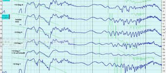
  • Peerless SLS 5" P830945; This is working in a 6 ltr net volume to produce F3/10 of 52/38. It also has higher sensitivity than ANY other 5.25" that can accomplish this bass extension feat. Being that, it has a lower Zmin above tuning at 150Hz of 2.3 ohms. This means the woofer lowpass coil has to be an air-core, and I was able to yield a Zmin of 2.6 ohms without speaker wires. This means it should be of a roughly stable 3 ohms by the amplifier sight, and a fairly stable 4 ohm load over all. It's a very minute area, and approaching 0 in terms of phase. Aluminum shorting ring, and long Xmax.
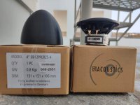
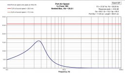
  • To accomplish this response in a small box such as this, there is no way you can use a port and tune low enough. It is just not possible. I was able to fit the SB Acoustics SB15SFCR-00 5x8" PR on the back of the cab. This involved using a midrange chamber of specific orientation to allow the PR to fit, albeit offset in one direction horizontally. 2x 0.5" x 1/8" thick washers and a stainless steel Allen-head M6x1 bolt were used to tune the PR to roughly 20Hz.
  • The Dayton Audio PC83-4 was used as the midrange. Being this is a 4 ohm driver, the xover landed at 650Hz to meld with the woofer to both keep impedance and xmax in check. Being the woofer is a 5.25", the off-axis response is really not impacted heavily. The tweeter and it landed at 5kHz, and the 83 has good enough off-axis response to make this just fine and keep the vocal range centered in the mid driver. The 83 also has a very benign breakup, likely due to its coated woven fiber cone, and it sounds fantastic. A decent xmax and copper cap keep it clean. 1 ltr sealed is all it needed, and this is a benefit here to give the woofer all the volume I could. (I used this midbass in the OSFA blue tooth speaker, and really liked its qualities. I also paired it with the following tweeter as a 2-way. I liked the results.)
  • The Dayton DSN25F-4 Designer Series 1" was chosen to finish off the top 2 octaves, 5k+. Paired with the PC83-4, the acoustic offset seems to be really similar, the CTC is small, and the frame is tiny. Sensitivity is 95dB, so it is heavily padded -13dB, and is loafing with a very easy living. On axis, there is a small rise at 12kHz of about 3dB, but most won't notice it. Just above the tweeter axis about 15* or +4", the rise disappears and the response is really smooth and flat. A copper cap keeps it clean. FF damps the Fs. Possible bonus? These tweeters have been known to be slightly leaky. If yes- then the midrange is in a slightly aperiodic box. If not- it does not impact the performance. Of note; I had a bad unit and PE replaced it. They are on back-order until July currently.
Place all into blender and pulse 3 times....

Xover points were 650/5k, not as pictured in the last sim-snap. I did not measure impedance and save it yet, so this should be close.
Xover board is 6" x 6.25". I ended up upgrading to the Cebo caps on the tweeters after the photo was taken. Much better, IMO.
Current prices:
P830945 = 36.98
PC83-4 = 12.98
DSN25F-4 = 18.98
SB15SFCR-00 = 35.70
Denovo 0.23ft^3 knock-down box = 26.98

Xovers as built: ~$115.20 each. I used the $4.00 75uF caps from ApexJr, and est a $1/resistor. The rest of the amounts are from Meniscus' website.

Total/cab comes to $247.14 including the cabinet, or $494.98; not bad for a compact 3-way! (My cost was $300 from discounts, salvaged upwound coils, used and free drivers, FWIW.) Most of the time, by the time you have xovers factored in with drivers on a 3-way, you're already in the $500+ category without even thinking about cabinets.

Attachments

  • IMG_4778.JPG
    IMG_4778.JPG
    579.6 KB · Views: 936
  • PurveryorSim2Final&VoicedXover.jpg
    PurveryorSim2Final&VoicedXover.jpg
    62 KB · Views: 813
  • PurveyorBox.jpg
    PurveyorBox.jpg
    207.3 KB · Views: 875
  • PurveyorCab.png
    PurveyorCab.png
    58.8 KB · Views: 781
  • Purveyor-RightHD+15degV_or4inches.jpg
    Purveyor-RightHD+15degV_or4inches.jpg
    134.2 KB · Views: 787
  • PurveyorSim2_AllMeasurements.jpg
    PurveyorSim2_AllMeasurements.jpg
    351.3 KB · Views: 657
  • PurveyorSim2_TweeterAxis_+15DegVRight_12thoctaveSmoothed.jpg
    PurveyorSim2_TweeterAxis_+15DegVRight_12thoctaveSmoothed.jpg
    67.8 KB · Views: 1,156
  • PurveyorSmallZoomFronts.jpg
    PurveyorSmallZoomFronts.jpg
    47.2 KB · Views: 1,231
  • SubtletySim1.jpg
    SubtletySim1.jpg
    246.8 KB · Views: 1,229

Technics SP10 stuff not mentioned yet

I haven't seen any mention of one of the SP-10's nicest features--the capability of lowering arm, sitting down in the sweet spot, and using the remote (wired) control to start the music. Mine's a MKII and I also have MKIIA. Anyone else doing that? Not sure if this feature is on MKIII or SP10R.
I made a video I can't find, but it's the bottom plate of my sp10 MKII hanging literally off a string. When struck with a knuckle, it rings like a bell. If anyone else removes theirs, listen for any changes in sound and report your findings. I'll see if I can redo the video Thanks.

--Al

Alpair 12 break-in question: 2mm?

Okay, tomorrow we build the Solstice cabinets and install the Alpair 12s. My next dumb question (hey, I gotta learn somehow!) concerns the break-in period. Mark suggests 2mm for 20 hours, and 4mm for 200 hours. Okay, I have no idea what that means! Is 2mm the volume of a normal conversation at a dinner table? Is 4mm the volume of your TV? Any help would be wonderful, because I really want these Solstice to shine!

Alnico-CA80 15 inch fullrange speaker

Never built a full-range speaker before. But I have to say that this sounds really good. Deep bass and particularly detailed highs for this speaker size. Very satisfied with the result!

Greetzzz Hondasnl

Attachments

  • PDFtoJPG.me-1 (1).jpg
    PDFtoJPG.me-1 (1).jpg
    838.4 KB · Views: 547
  • PDFtoJPG.me-2 (1).jpg
    PDFtoJPG.me-2 (1).jpg
    459.8 KB · Views: 520
  • DSC_0180.JPG
    DSC_0180.JPG
    508.3 KB · Views: 482
  • DSC_0182.jpg
    DSC_0182.jpg
    430.6 KB · Views: 447
  • DSC_0186.jpg
    DSC_0186.jpg
    308.6 KB · Views: 455
  • DSC_0192.jpg
    DSC_0192.jpg
    271.7 KB · Views: 326
  • DSC_0065.JPG
    DSC_0065.JPG
    466.4 KB · Views: 342
  • DSC_0229.JPG
    DSC_0229.JPG
    392.9 KB · Views: 344
  • DSC_0261.JPG
    DSC_0261.JPG
    495 KB · Views: 434
  • DSC_0231.JPG
    DSC_0231.JPG
    246.1 KB · Views: 435

What should i use as Ql, Qa and Qp values.

I recently build a subwoofer I used the parameters
Ql: 15
Qa: 30
Qp: 30

1677706775710.png


I should have gotten this frequenty response from a 6,5 inch dd506d2 in a double tuned bass reflex

But for my ears and my phone (using the app spectroid) it sounds more like this:
Screenshot_2023-03-01-22-44-10-353_org.intoorbit.spectrum.jpg

It has a huge peak around 20hz (at low volumes (such as the volume i took these measurements with) it makes port noise here so that could be a factor. The port has a diameter of 68mm so 2.677 inches with a length of 80 cm so 31.5 inches for a 6.5 inch driver.

When I use these parameters
Ql: 100
Qa: 100
Qp: 100
I get this response:
1677707591682.png

Which looks more like the actual response then the ones with "normal" Ql. Qa and Qp parameters. So now I don't know what parameters to use for my next build. Suggestions would be appreciated 🙂

Sb12pfc25-4 with pods(housing)

For sale a pair of wonderfull sb12pfcr25-4ohm drivers by sb acoustics, never used, just out of the box for the photoshooting.
The plan was to used as midrange at the pods, but the plans have changed.

Together I will ship a pair of 3d printed pods, very good and steady construction. They can be sanded and painted to any color you like, and can be used at car as midrange.

100 euros plus shipping
Pods can be sold separately at 50 euros for the pair. Also I can print pods for tweeters if you want to pair them.

Attachments

  • received_717459412918424.jpeg
    received_717459412918424.jpeg
    130.4 KB · Views: 97
  • received_682204823602258.jpeg
    received_682204823602258.jpeg
    169.4 KB · Views: 98
  • received_598779742254122.jpeg
    received_598779742254122.jpeg
    121 KB · Views: 92
  • received_2509585269182717.jpeg
    received_2509585269182717.jpeg
    138.7 KB · Views: 101
  • received_678097493861494.jpeg
    received_678097493861494.jpeg
    164.3 KB · Views: 95
  • received_1360839814656913.jpeg
    received_1360839814656913.jpeg
    138.6 KB · Views: 105
  • received_881314299724880.jpeg
    received_881314299724880.jpeg
    111.1 KB · Views: 98
  • received_5676117592435348.jpeg
    received_5676117592435348.jpeg
    129.2 KB · Views: 92
  • received_893810861746064.jpeg
    received_893810861746064.jpeg
    130.1 KB · Views: 92

Small 2-Way with Ciare 6.5" and 1,4"compression driver (Unibox sim)

Hi!

Im trying to build a small 2-way with high efficency. My plan is to use the Ciare HWG 160 for the Low/mid and a 1,4" driver for mid/high
Crossover freq at 1200.

This is my first simulation in Unibox so feel free to comment.

Attachments

  • grund.jpg
    grund.jpg
    138.5 KB · Views: 184
  • Exec.jpg
    Exec.jpg
    100.3 KB · Views: 167
  • freq.jpg
    freq.jpg
    102 KB · Views: 145
  • Port.jpg
    Port.jpg
    87.8 KB · Views: 139
  • step resp.jpg
    step resp.jpg
    107.2 KB · Views: 167

For Sale Hypex Nilai Kits or assembled amps (Monoblock and Stereo)

I have some spare Hypex Nilai Kits here (unused / new):


2 pc. of Hypex Nilai500DIY 1CH 500W Monoblock
(as seen here: https://www.diyclassd.com/product/nilai500diy-500w-mono-kit/184)

  • Kit: 980€ / each
  • assembled amp: 1080€ / each


1 pc. of Hypex Nilai500DIY 2CH 2x250W Stereo
(as seen here: https://www.diyclassd.com/product/nilai500diy-250w-stereo-kit/185)

  • Kit: 1480€
  • assembled amp: 1580€


I ship to addresses within the EU only.
(Shipping cost DHL w/ insurance comes on top)


Paypal fees are still added if you don't want to use 'payment to friends and family (“Sending to a friend”)'
bank transfer is also possible.


if you are interested you have to contact me via PM please

pictures will follow ...


SOLD ...

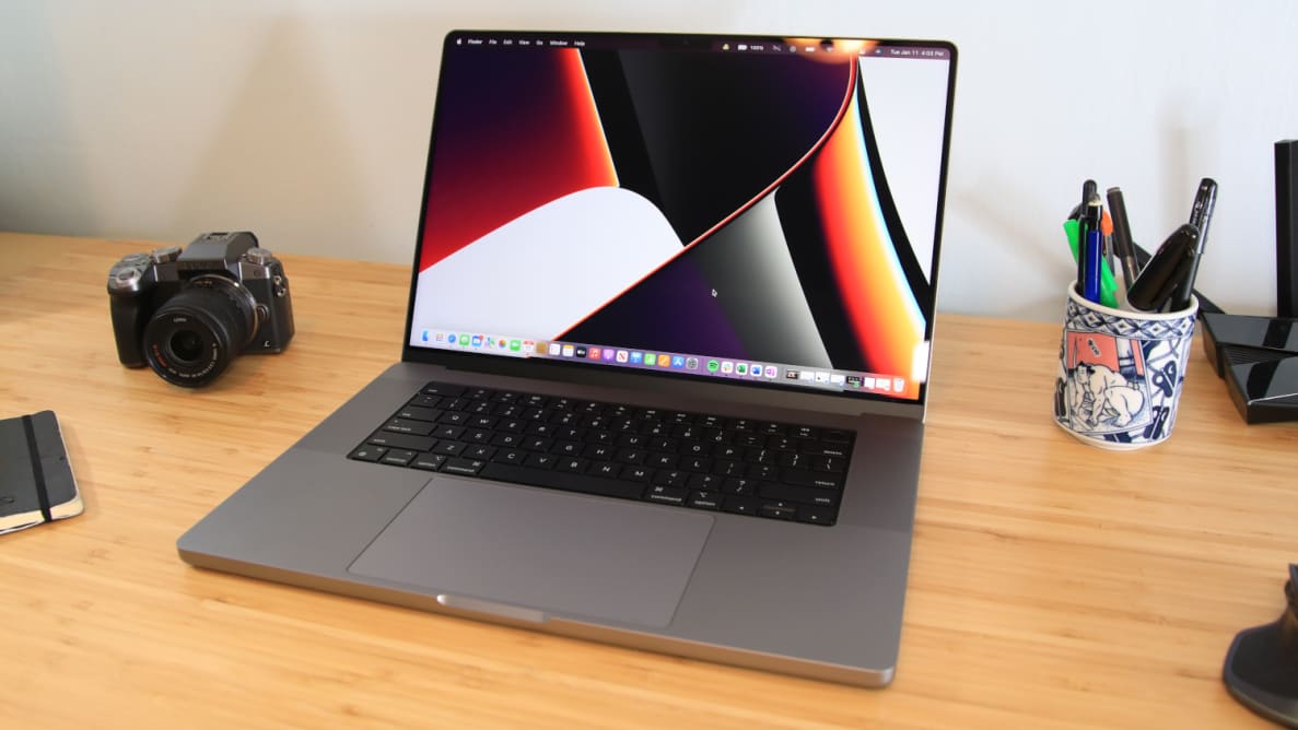
Why Does New Macbook Sound So Good?

apple-macbook-pro-1.jpg


Is anyone aware of how/why the speakers on the new Macbook Pro sound so good?

I normally listen to a set of Infinity ILS speakers in my office, connected to a pretty decent single ended solid state amplifier.

Tonight I was too lazy to get up and change tracks using my audio player, so I used my Macbook Pro instead. No additional speakers, no additional amplification, no external DAC. Just the speakers that come with the Mac.

And I was kinda astounded by how good they sound. In particular:

With natural recordings, there is honest-to-God soundstaging... from a laptop that's 36cm wide. With good recordings, the stage is significantly wider than the laptop itself. I'd estimate about 54-72cm wide.

I have a big project due tomorrow, so I don't have time to sift through Apple patents. I'm just going to make a few educated guesses:

1) I really enjoy 3D printing, but because of that, I've never invested a great deal of effort into making enclosures that are incredibly inert. The Macbooks are cut out of aluminum with a waterjet and they are STURDY. My Windows laptop feels like a toy by comparison. Is it possible that the solidity of the laptop's enclosure makes it sound dramatically better?

2) Apple is using force canceling midbasses in the Macbook, a la Kef

3) The soundstage is so surprisingly wide, I wonder if there's some kind of DSP processing going on, a la Opsodis or Ambiophonics?

4) I can't stand the Mac keyboard, so I keep the laptop quite far away, about three feet from my ears. (So I have room for a nice keyboard in front of the laptop.) So the sheer distance is probably improving soundstaging.

Anyways, if you have one of the new 16" Macbook M1 Pros, put some music on and let me know what you think. I'm not going to pretend that this can get loud, but if you're listening at a polite level at your desk, it's surprisingly good.

Citation II monoblock noise

I have a HK Citation II that has been converted to monoblocks. Over a period of time, one channel starts popping, like a plate pop, after the unit warms up. We switched tubes, replaced resistors that were getting hot to no avail. Any help would be appreciated.
There are photos of both here:
https://www.usaudiomart.com/details...kardan-citation-ii-mono-blocks-sell-or-trade/

Balanced to unbalanced solution

Hello,

I need a solution to go from a balanced DAC to unbalanced (RCA) inputs on one of my amplifiers and for subwoofer input.

I'm aware of 3 options
  1. Cable based - lifting or ground shields / pins as appropriate
  2. Transformer based - passive solution
  3. OPamp based - active solution

My searches aren't really finding some good "off the shelf" solutions. Bad terms, or something not really used / recommended. I don't know.

In anycase, I've found this, but being aliexpress - I don't know quality of the opamps in question and whether they are even genuine.
https://www.aliexpress.com/item/1005003718000938.html

Claimed to use a TI I believe INA137PA. Again.. whether genuine or not and whether this device is any good for the task.

powered by a suitable 15v AC supply.

If the above is suitable - dumb question. Can a single AC supply be wired to multiple boards? I assume if the current demands are less than the supply is capable of, no problem?

Thanks,
David.

6L6 Power Amplifier - A grandmasters unfinished dream

6L6 Power Amplifier - A grandmasters unfinished dream

I have been approached by the son of a local electronics engineer who passed away last year. He was still working on his ultimate valve power amplifier system.

All the parts and schematics were collected and I am now trying to make sense of it all. It is a difficult task to take on since the man who designed it is not available anymore for any comments.

The amplifier is quite elaborate. 100 watt per channel, servo bias control, overload protection as well as grid drift compensation and cathode windings in the output transformer.

In the notes the man stated that he battled with the overload that reset itself after a short while - he wanted it to stay latched when it tripped. Also, there is a spike pulse on the 500 vdc regulator.

If any member here is keen to cast an eye on the schematics, I would be very grateful.

Attachments

  • 20230114115144362_0001.jpg
    20230114115144362_0001.jpg
    309.7 KB · Views: 560
  • 20230114115316388_0001.jpg
    20230114115316388_0001.jpg
    331.6 KB · Views: 559
  • 20230114115356915_0001.jpg
    20230114115356915_0001.jpg
    181.6 KB · Views: 567

guitar preamp simulation

Hi all, I am trying to finalize my schematic for a standalone guitar preamp based off ceriaton chupacabra. I have implemented the output cathode follower from a soldano X88R and I can't seem to get it to look right in the simulation.
I need the output to be line level (1Vrms) and I do not know what values I should be using for the B+ drop resistors (R1, R2, R3 in the schematic, R11, R30, R32 in the sim) as just messing around with them I cannot get the dc voltages to match what the voltages should be (per ceriatones voltage chart and what I have found in a thread discussing an x88r clone for the output stage)

If anyone could give me some help figuring out where to go from here I would greatly appreciate it.

Attachments

  • Schematic_Chupacabra preamp_2023-02-25.png
    Schematic_Chupacabra preamp_2023-02-25.png
    35.2 KB · Views: 156
  • hamburger.asc
    hamburger.asc
    9.5 KB · Views: 86
  • Screenshot (33).png
    Screenshot (33).png
    31.9 KB · Views: 152

Down4sound JP23 Schematic

On my bench is a Down4sound JP23 amplifier. It uses 3205’s in the power supply circuit, and 640N’s in the output circuit. It came in with some swollen capacitors, short power supply fets, and short output fets.

I’ve removed all the fets including the rectifiers. I’ve disabled the protection circuit and when I power it up without any fets, I get proper drive on all the gate pads in the power supply.

The problem I’m getting, is when I fit the amp with two fets per side, the fets are heating up. The drive looks ok on the gate, but the drain looks like it’s not being pulled all the way down.

There are no rectifiers in the circuit so what could be pulling enough current to make these babies hot? Also, does anyone have a schematic for it or an equivalent?

Thanks!
9D94CE62-88E7-47D6-996A-D9D7AE6B9A74.jpeg

CDM 4/19 Standard / Composite Compatibility?

Great place here, have not posted for ages but I've had lots of useful info as I'm getting into CD players.

The Marantz CD65 II SE is said to use the 4/19 composite mechanism (metal and plastic I believe), whereas the CD65 II (and many others) use the standard 4/19, plastic only.
Can these be swapped? If I get a SE model I'd like to be able to fit the more common standard plastic one if necessary, even if there is a slight drop in performance.

I have searched but can't find the answer; it may be a silly question but better to ask!

I am considering having a CD65 II SE modded and converted to NOS, then I'd lampizate it myself.

FS 10x ASC X386S capacitors black coloured 30µF / 400VAC/800VDC

FS for a friend:
10x ASC X386S capacitors black coloured 30µF / 400VAC/800VDC from Vinylsavor

all caps are unused and located in germany.

blow out sale 250€ for all 10 together . Pse ask for dhl shipping costs.

Attachments

  • IMG-1864.JPG
    IMG-1864.JPG
    459.8 KB · Views: 144
  • IMG-1865.JPG
    IMG-1865.JPG
    453.7 KB · Views: 150
  • IMG-1866.JPG
    IMG-1866.JPG
    506.6 KB · Views: 123
  • IMG-1867.JPG
    IMG-1867.JPG
    388.9 KB · Views: 130

Mission 778 power amp adjustment

Hi. I have an early 80s mission 778 integrated amp (pre-Cyrus One, mosfet output devices) which I have just repaired (vol control needed replacement). It's sounding rather good but it does run hot, even at low volume levels. I've no idea if this is normal.

The power amp circuit diagram is here - Mission 778 - Manual - Stereo Integrated Amplifier - HiFi Engine - page 2 of the "schematic" link.

And you can see there is a trim pot in each output channel, with voltage measurements given. Looks like these measurements are close but not identical for the + and - rails. I've not yet measured the channels of my amp, but in general should I be looking for the + and - measurement points shown (marked as 14.6v and 15v respectively on the diagram) to be the same?

If these measurements are not the same / near the values given, would this cause the amp to run hot, or is it nothing to do with that?

I'm fairly handy with a multimeter and soldering iron but I do not understand the finer points of MOSFET power amp design.

The output devices are fairly substantial T03 can devices fitted to a substantial finned heatsink. However after nearly 40 years I guess the thermal grease may be past its best?

Any advice appreciated.

Paul

Eton seems to be on the rocks, at least in North America

I visited www.solen.ca (Solen Montréal) website and I was hit with an "EVERYTHING MUST GO!" style banner, closeout pricing on all their Eton inventory.

Well, that's a shame--the more I hear the 5-312 Kevlar woofer-mid, the more I love it.

The Jungle Telegraph tells me that Madisound is dropping the line also, just perhaps with less fanfare.

Too bad.

john

Need recommendations on 1000uF 50VDC power caps <18mm tall for Soundstream Refrence 604

Hi all, new to the forum here. I am currently getting everything together/setup for installing a sound system in my old W123 Mercedes. I have a McIntosh MX406 HU, Soundstream Reference 604 Amp, and have a variety some old-school MB Quart premium speakers and crossovers incoming. I'm am refurbing everything before install.

Everything works on the Soundstream amp and it is clean inside (except for some discolration around the power chokes, but amp has been bench-tested). However, I am going to be re-capping it. I am having trouble finding replacement caps for the 4 big power caps that are rated at 1000uF and 50VDC. They are currently Nichicon VS-series (cannot find datasheet regarding these anywhere) and 20mm diameter x 15mm height. The big issue is the height! I can go a little taller than 15mm, but not much as there is no clearance beyond ~19mm. I cannot find any caps to fit these specs - all seem to be 20mm, 25mm, or 31.5mm tall which will be too tall. Does anyone know of a current cap that will fit these physical restraints for this purpose?

Thanks,
Allen

Attachments

  • PXL_20230223_022017763.jpg
    PXL_20230223_022017763.jpg
    667 KB · Views: 96
  • PXL_20230222_231152900.jpg
    PXL_20230222_231152900.jpg
    366.3 KB · Views: 98
  • PXL_20230228_010058672.jpg
    PXL_20230228_010058672.jpg
    398.6 KB · Views: 104

Cathode Feedback from Output Transformer Secondary Free for All

A thread devoted to the subject of CFB from OPT secondary side to output tube cathode.

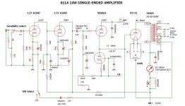
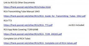
I've moved the 811 SE amp over here for a start. Looking at the operating conditions the claim of 24W audio doesn't make sense.
Running 80 mA plate current from a 600V supply looks like 48W plate dissipation, about the limit given in the RCA TT4 Transmitting Tube Manual.
In Class A Triode efficiency max's out at 25W. That can be pushed somewhat farther but it is no longer Class A & distortion increases.

I tried plotting the Tango 5K loadline on a poorly copied image of 811 plate curves. Trying to flatten the RCA TT4 manual
to stuff into the scanner was a real problem, By using an olde formula found in many RCA tube manuals the loadline never got more than 12W.

I've included some very interesting links, some for the fans of transmitting toobz.

No Sim to measure DF yet, I'll stuff that into the thread later. Time to get outta here for a few hours, 👍

Attachments

  • 811A 24W SE Amplifier.jpg
    811A 24W SE Amplifier.jpg
    85.3 KB · Views: 882
  • 811A SE Amplifier PS.jpg
    811A SE Amplifier PS.jpg
    106.7 KB · Views: 628
  • 811A Plate Curves.jpg
    811A Plate Curves.jpg
    57.1 KB · Views: 423
  • Tango SE OPTs.jpg
    Tango SE OPTs.jpg
    72.6 KB · Views: 327
  • 811A Plate Curves & Power Limits A w Captions.jpg
    811A Plate Curves & Power Limits A w Captions.jpg
    22.4 KB · Views: 308
  • Links to RCA & Other Documents.jpg
    Links to RCA & Other Documents.jpg
    93.6 KB · Views: 538

For Sale New pair of Dayton RS225-8 and pair of Wavecor SW182BD01

Have a new pair of Dayton RS225-8 woofers $100pr plus shipping and new unused pair of Wavecor SW182BD01 small subs $150pr plus shipping. Both from projects that went in another direction. Both pairs still in original packaging and never used.

Attachments

  • dayton RS225-8.jpg
    dayton RS225-8.jpg
    89.2 KB · Views: 120
  • Wavecor SW182BD01.jpg
    Wavecor SW182BD01.jpg
    98.2 KB · Views: 129
Projects by fanatics, for fanatics
Get answers and advice for everyone wanting to learn the art of audio.
Join the Community
507,346
Members
7,866,391
Messages

Filter

Forum Statistics

Threads
405,202
Messages
7,866,391
Members
507,346
Latest member
sarsicism.