Budget 1.4" driver & waveguide combo

Just thought I would post my latest purchase I was very impressed with these especially for the price. The waveguides were purchased from aliexpress for a total of $63.25 They are 1.5" throat 13.3" W x 7.2" H x 5.1" D The waveguide is built very good 1/4" thick and the mounting flange is 3/8" thick. The drivers are B&C clones Lase N-75 bought off eBay $236.48 for a total of $279.73 not bad at all especially for the quality. I could have saved around $100 buying the drivers off aliexpress the reason I bought them from eBay is if I did not like them they would be easier to return technically I could return them to eBay now that I know I love them and buy them from aliexpress but I sell on eBay also and I don't like getting returns so did not want to be shady just to save $100 plus I really like these drivers. Here is the frequency response with no xover and with a xover. I have had in the past Altec 288 long time ago Radian 745 neo & radian 850's a couple years ago those are the only large format drivers I have experience with I have had many small format drivers Vinatge Altec 808,802,902, JBL Le-175, B&C DE-250, Beyma cp-380, radian 475 These are the first titanium diaphragm drivers I have owned and at 52 years old I feel I wasted a lot of valuable listening time with aluminum and non metal diaphragm drivers. These titanium diaphragm drivers have more detail than any driver I have ever owned and at the same time they are smooth and relaxed like radian 850's but more detail and they extend out quite a bit perfect for my taste makes me wish I would have tried some titanium diaphragms drivers a long time ago. Anyway just thought I would share my findings.
Screenshot from 2023-11-09 16-43-15.png
Screenshot from 2023-11-09 17-20-38.png
JBL waveguide1.jpg
JBL waveguide2.jpg
lase driver.jpg

Attachments

  • Screenshot from 2023-11-09 16-43-15.png
    Screenshot from 2023-11-09 16-43-15.png
    12.2 KB · Views: 154

Hamlet Speaker - Compact version

Re Hamlet Speaker - New More Compact Box Deign:

My circumstances have changed somewhat last year and my bread-and-butter work was upgrading Oppo 105 and 205 players (plus the occasional 203) and that has largely collapsed since streaming has taken over. The upgraded Oppos are amazing for streaming if you know how, but that is not so well known. Also I am now considered semi-retired by the government. So it is with some regret... please read on.

I was approached by a client and as part of that assignment I did something that was a logical thing to do, I redesigned the box of the Hamlet so that it is a bit more compact all round and also a definite improvement in a number of ways. The regretful part is that it is commercial and that it will cost a very fair $120 into my PayPal account. I put my trust that the person will not pass it on to others. And since the cost is so modest, only a cheapskate would do that. So it will be on the honour system.
1737183635269.gif


Below is the overall dimensions:
1737183666354.gif

It can be used vertically as stereo pairs or in multi-channel situations, and of course on its side as a front centre channel. The drivers continue to be "MFC" and the crossover has not changed. Same goes for the Tweeter and Waveguide. There is also a space created at the rear of the cabinet where the Black Crossover PCB fits, the Green PCB does not fit.

You can use the PayPal link below.

www.paypal.com/paypalme/BjoernRasmussen/120

Hope it meets with some approval.

1737183554714.png

Rabco SL8E Photoelectric Servo Control Retrofit

I’m starting this thread primarily as a place to exchange ideas for repairs, modifications, and photoelectric servo control systems to help keep the extant population of Rabco SL8E (and SL8) linear tonearms alive and working better than new. Ideas here could also be useful for other diy servo-linear arm projects, and conceivably spin off into new threads. First, a few requests for this thread that I hope everyone will respect and abide by:

This thread is intended for those who own, have built, like to tinker with, are addicted to, or otherwise admire electric/electronic servo-controlled linear tracking tonearms. Rabco SL8E owners move to the front of the line.

and:

PLEASE, no ‘servos are always in error’ arguments, no debates over servo linears vs passive linears, servo linears vs air linears, servo linears vs conventional pivoted tonearms, etc. Those skirmishes and battles have been fought out elsewhere on the internet, and invariably degrade into nuclear exchanges that trash the original thread. If you are anti-servo that’s fine, but you already have plenty of other forums to post your views and comments, and you’ve probably already done so.

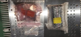
To launch this thread, I’m posting my most recent work - a minimally invasive diy photoelectric retrofit to replace the troublesome catwhisker contacts on the Rabco SL8E. By ‘minimally invasive’ I mean that it requires no drilling or cutting of the carriage or original structure and is totally reversible (although I can’t imagine why you ever would want to undo this modification). The modification requires detaching the carriage and battery/drive motor housing from the track but does not require disassembling the horizontal/vertical arm pivot bearing assembly or the lift switch assembly. I put together a shared public shopping cart on Digi-Key (no financial interest) that includes all the electronic parts for the project. There is one part that you will have to diy that requires cutting, drilling, tapping and that is to fabricate a mounting block for the two photoelectric sensors. If you want to do a more extensive tear-down and include modifications like re-wire the cartridge leads/interconnects, replace the bead chain with a timing belt, etc., that is up to you and whatever you think will yield the audible improvements that you are looking for. This modification is only for the servo control. It will require advanced soldering skills and dexterity with a normal temperature-controlled soldering station.

My journey into modifying SL8E’s began in 1973, when a friend of mine handed me a SL8E and said “here, see what you can do with this”. He gave me full artistic license, and the goal was to optimize the design for the original mega-high-compliance ADC XLM cartridge. At that time, I had access to the machine shop at my engineering college, and I had access to a pretty good imagination as well. I replaced the entire OEM arm assembly with a low mass viscous damped unipivot and this eventually turned into a construction project article that was published in the 3/76 issue of The Audio Amateur magazine. I built two more SL8E’s with the unipivot mod, one for another friend and the other for myself. Since minimizing effective mass was a primary objective of the original mod, I deleted the convenient OEM vernier adjustment mechanism for setting 90-degree tracking angle and replaced it with a lightweight semi-fixed wand. The original mod retained the OEM catwhisker servo control. More on that later.

attachment.php

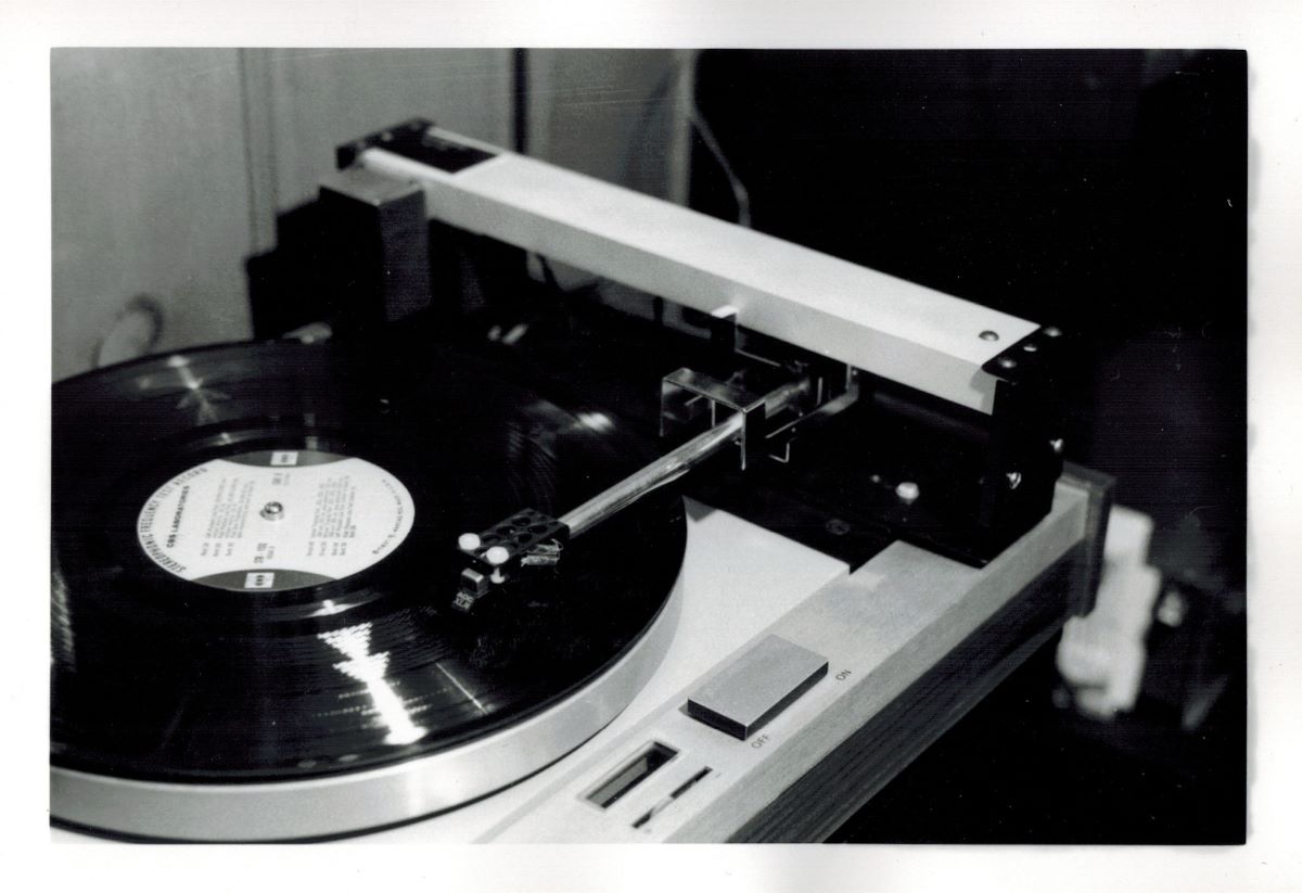
The original TAA 3/76 mod

That arm has remained my mainstay ever since and has provided me with unparalleled performance. (I’m not sure if that’s a pun or an oxymoron). The unipivot mod initially had a Rube Goldberg-ish cueing system as shown in the TAA article, but it worked reasonably well. By far, the biggest reliability problem turned out to be the progressively worsening erratic behavior of the catwhisker contact system that controlled the carriage drive motor. The classic failure mode was airborne contamination, which resulted in the cue motor lifting in the middle of the record. I went through years of routine maintenance cleaning of the catwhisker contacts. This helped for a while, but eventually the situation became unworkable. I designed a non-contact photoelectric servo control system out of necessity. While working on that I devised a much-improved cueing mechanism as well, which reduced the ridiculously high cueing height to just above the record surface and made the cue height vernier adjustable. The new photoelectric servo control circuit and cueing system has since worked flawlessly.

attachment.php

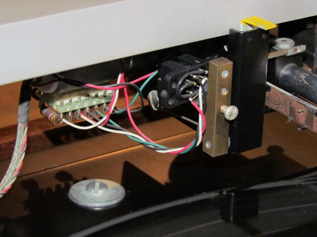
The original photoelectric upgrade, with electronic parts mounted outboard.

I initially thought the photoelectric circuit should duplicate the on/off action of the OEM catwhisker contacts. I contemplated employing a Schmitt trigger, but was up against the limited real estate available within the carriage for all the added circuitry. I though I could get away with achieving sharp on/off switch action by just using a simple circuit with high gain transistors, but I ended up being wrong about that. The carriage motor ran quickly at the lead-in groove, then settled down and ran slowly during the program material. Instead of start/stop motion like the OEM servo control, the carriage motor kept running continuously, and adjusted its speed in step with the varying groove pitch. Eureka! By serendipity, I ended up with continuous variable speed carriage control instead of mimicking the OEM on/off action. The continuous variable speed action has proven to have several advantages. First, it eliminated jackrabbit start, overshoot, and stop motion (“crabbing” as anti-servo crowd calls it). Second, and far more important in my estimation, the continuous slower speed operation of the carriage drive motor dramatically reduces physical motor noise.

I eventually tracked down the source of the beneficial ‘soft’ control action. It is the orientation of the aperture window in the photosensors and the fact that the aperture of the light-sensitive part of the phototransistor has a finite area. The sensor window is a rectangular slot. The manufacturer intended that the edge of the customer’s interrupting flag line up with the long edge of the sensor window, to minimize the transition time of the on/off state switching. Because of physical constraints I oriented the sensors at 90 degrees, such that the interrupting flag crossed the sensor window the ‘long’ way. Arm motion interrupts the optical beam gradually, much like the slow action of a solar eclipse, and provides the variable gain in the feedback loop which makes the carriage drive motor run smoothly in a continuous variable speed mode.

I’ve had several requests to share my servo control circuit and I have posted it on the Rabco SL8E Club thread over at LencoHeaven. The catch is, that the original circuit was developed for my unipivot configuration which had the photosenors mounted externally under the carriage and a semi-fixed wand on the arm pivot that un-interrupted the beam to advance the servo. The only practical way to design the photosensors to be inside the carriage requires a mounting arrangement that 
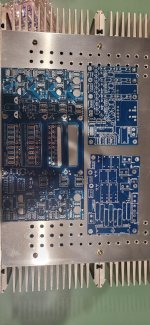
interrupts the light beam to activate the servo. This mounting arrangement is better suited as a retrofit mod because it retains the functionality of the OEM vernier adjustment mechanism for setting zero tracking error. I own two more OEM SL8E’s and decided to reconfigure and adapt my original photoelectric control circuit into a version that is optimized for installation on a stock SL8E. I retrofitted one of my extra SL8E’s with a redesigned photoelectric servo-control and I’m presenting those modification steps in this thread. I debated on whether to put most of the components on an externally mounted board as in my original mod, or to mount all the parts on/in the carriage for a clean, original look. Consider that a big advantage of the former is that an externally mounted components board makes it easy to tweak parts values in order to optimize performance. I felt confident that my circuit design should work because of the time I spent breadboarding and testing it so I opted for the latter. Both approaches have merit and you should choose a path based on your diy preferences.

OK, so what evidence can I show to demonstrate that this is more than just another mod that was done for the sake of satisfying some expectation bias? To test compare the performance of the mod’ed and the stock versions of the arm, I fabricated and attached a diagnostics cable to the photoelectric retrofitted SL8E and another to the OEM stock SL8E. I monitored the servo ‘command’ signal, the right channel audio, and the actual carriage drive motor voltage while playing a typical music LP and displayed the three traces on a storage oscilloscope set to operate in auto-erase mode. The effect is very similar to a heart rate monitor display that you see on one of those medical TV soap operas.

Here is the scope trace mp4 for the stock OEM SL8E with cat whisker contact servo control:
YouTube

The upper trace is the contact closure command signal from the cat whisker to the carriage drive servo. The middle trace is the audio, straight from the cartridge with no RIAA EQ. The bottom trace is actual carriage drive motor voltage. The cat whisker contact does not provide a clean control signal, particularly on the tail end release. The motor voltage exhibits a repetitive pattern of jackrabbit start to full speed, then coast to a stop, then sit and wait until the next burst. (Note: the polarity of the trace is inverted due to the Positive Ground power supply, sorry). Clearly, this drive is ‘crabbing’ its way across the record. In fairness, I did take this SL8E apart, cleaned the cat whisker and contact post wires, installed a new foam gripper pad, cleaned, lubed, and adjusted the complete operating assembly to what I believe is factory spec. How much angular error is introduced by the crabbing? I suppose it could be analyzed and calculated, with a probable result that the angular error is less than that of a 9” pivoted arm, but let’s let that sleeping dog lie.

Here is the scope trace mp4 for the modified SL8E with photoelectric servo control:
YouTube

The upper trace is the command signal from the photoelectric sensor to the carriage drive servo. The middle trace is the audio, straight from the cartridge with no RIAA EQ. The bottom trace is actual carriage drive motor voltage. My initial reaction (and maybe yours) upon seeing these traces was “jeez, after all that work, this looks like crap”. After stewing for a while, I started to pick this apart a bit. Neither the upper trace command signal from the photoelectric sensor nor the lower trace of the actual carriage drive motor voltage exhibit any of the “full-on/off” jackrabbit start/stop behavior of the OEM stock cat whisker servo control – that’s been eliminated. The motor is now running continuously. To explain the voltage vacillation, look at the timing. The vacillation period is 1.8 seconds or 0.55Hz. The servo is unidirectionally attempting to follow the record eccentricity! I found that the magnitude of the vacillation corresponded to the magnitude of the eccentricity of the record being played. Well, that’s settled – all playback systems are compromised by eccentric records, so let’s move on.

It occurred to me that, if I had a record centering servo system on the spindle, and if I fed it a properly filtered and phased copy of this arm’s error correction signal, the record should perfectly center itself automatically while playing within a few revolutions. Hmmm.

Next post – the mod.

Ray K


Attachments

  • 0A_The Original Mod.jpg
    0A_The Original Mod.jpg
    614.3 KB · Views: 2,691
  • 0B_New Photoelectric.JPG
    0B_New Photoelectric.JPG
    163.2 KB · Views: 2,702

Mono-Stereo-Mono math question

Over the years I picked up 78s that I thought were cool or interesting with the hopes that down the line I would have a system to play them on. I figured i would mount a 78 cart on an AT-120 and live with the built-in RIAA curve of my phono pre-amp. Fast forward to now and I recently found a nice Dual 1214 which plays at 78. Then I found a Bell 2200C mono amp which has a heap of phono EQ settings in addition to RIAA. My first thought was to purchase and mount a 78 cart and hook up an extra speaker to the amp and I'm all set .... but as I started researching carts, I realized it's not that simple. The modern 78 carts are wired mono but are designed to be mounted on turntables with stereo outputs. The Bell uses a single phono input (it actually has 3 inputs - MAG 1, MAG 2 and CRYSTAL) My natural instinct is to use a Y cable or a summing box .... but I believe that would boost the signal and overdrive the input (plus there is no point in summing 2 parallel mono signals, I would love to avoid unnecessary steps in the chain.) That brings me to the conclusion of using only 1 single RCA cable, that should do the trick.

Here is the math: For the sake of example, if I use an AT-VM95SP cart on the Dual, it's rated output is 2.7 mV (1 kHz, 5 cm/sec.) and it's recommended load impedance is 47KΩ .... since those #s are based on a parallel output, would you split the total voltage and ohms in half for the signal coming through 1 channel of the RCA? Which input on the amp would you match it to? The Mag 1 input is rated for 30 millivolts or higher with a load resistor set at 27.000 ohms. The Mag 2 is rated for approximately 10 millivolts and the load resistor is 47,000 ohms. Obviously, crystal isn't an option. I'm not tied to the AT cart, I'm just putting it out there as an example. Any recommendations on a cart or specs that can be a better match would certainly be appreciated.

Thanks for reading all of this! Everything I search about Y cables is about splitting a single output to dual inputs, not the other way around.

Hello

Hello! I found my way here thanks to XrayTonyB’s YouTube channel that I was also fortunate enough to have found.

I am a lifelong engineer but I have spent my career working in the world of high-speed performance digital image and signal processing and not so much on audio gear.

I recently started a project restoring an early 1970’s Phase Linear 700B that a friend of mine gave me about 30 years ago. The last time it flame-linear’d I put it in a box and there it has been all these years. Since I recently decided that I wanted to study audio power amp design for fun, I thought this restoration would be a good learning experience. XrayTonyB’s series on Phase Linear really inspired me!

I’m sure I’ll have questions along the way and I’d be happy to share my progress if anyone is interested in such things…

Erich
Northeastern US

Channel not

Hello, I recently was given a stereo system (Marantz) as a gesture of goodwill. I was pressured because of growing family to give my vintage stereo away some years ago. Dual turntable, advent pre-amp, Brysten amp, Dahlquist DQ-10's. The new stereo has a marantz stereo amplifier pm551. When I wired it all up the amp only plays one one channel. I put the speaker wires on A and A channel 1 and 2 they both play. My question to this group is should I have the amp fixed, or should I just seek out a new or used amp?

US Coils Inductor Review

Short Review of US Coils

Background
I have quite a complex crossover network I am putting together.

I had some specific DCR requirements that had to be met.

A couple of members recommended US COILS. They have lots of different types of coils in all difference wire gauages so suit your needs.

Types
I ordered a variety of inductors to suit my needs. Most of these are their EQ air coils which they tout as "perfect lay". One of them is the XQ if I remember correctly. The iron core are their IQX.

Review
The good: The iron core inductors look very nice
The bad: These are by far the ugliest brand new inductors I have ever seen. The winding looks like crap. I planned to put this crossover on my wall but might hide it under my desk now. I have used super cheap inductors in professional builds that look 10x better than this. I will post up the pictures.

I am quite dissappointed in the quality. I will be testing the inductance of these in the next few days at our lab. If they measure out dead on I will forgive the aesthetics but I am not seeing how an inductor wound this way is going to measure out properly.

I will post up with measurements when I have them.

Let me know your experience with US Coils. Did your inductors look like this?

Attachments

  • PXL_20250226_233502036.jpg
    PXL_20250226_233502036.jpg
    328.3 KB · Views: 163
  • PXL_20250226_233437542.jpg
    PXL_20250226_233437542.jpg
    465 KB · Views: 158
  • PXL_20250226_233448970.jpg
    PXL_20250226_233448970.jpg
    390.6 KB · Views: 161
  • PXL_20250226_233440462.jpg
    PXL_20250226_233440462.jpg
    473.5 KB · Views: 151
  • PXL_20250226_233445286.jpg
    PXL_20250226_233445286.jpg
    421.5 KB · Views: 145
  • PXL_20250226_233840271.jpg
    PXL_20250226_233840271.jpg
    767.8 KB · Views: 147
  • PXL_20250226_233844026.jpg
    PXL_20250226_233844026.jpg
    589.5 KB · Views: 152
  • PXL_20250226_233509201.jpg
    PXL_20250226_233509201.jpg
    405 KB · Views: 151

Top cover aluminium grill/mesh attachment

I am thinking about using a black aluminum mesh on the inside of an aluminium enclosure under a large hole to provide good ventilation for an amplifier. Please see picture for the idea. Does anybody have any tips on how such a mesh might be fixed to the inside of the top cover? In particular, it shouldn't rattle or be easily pushed inwards or take up too much space inside the enclosure. Thanks!

Attachments

  • mesh.png
    mesh.png
    83.2 KB · Views: 184

Boston BA735 died

I have Boston Acoustic BA735 computer speakers that are two satellites and a sub-woofer. It’s old but for my purpose worked great for about 20 years. They have been connected to the same workstation pretty much for the last 10 years. Suddenly they have no sound at all. There was a little hum the past year or more but when I was listening to music I didn’t hear it. My hearing isn’t that great due to too many sporting events. The power indicator lights are on, so I think the power supply is good, but they are silent. When I adjusted the volume they used to make a little crackling noise, like the contacts were dirty. Zero noise of any kind now. I thought my PC needed an update or a new driver, but that wasn’t it. I tried a different set of speakers and they work fine. I opened the sub and all caps look good. The power indicator on the sub is also lit. These would be about $100 to get something reasonable but I’m just perplexed. I have a capacitor tester but I’m pretty sure you have to pull them off the board to test properly. I know there are versions of these BA735 speakers that are digital audio only, but mine have an analog and a digital input. I’ve tried other sources of sound without any sound either. They are simple boards and hardly any power. I have re-capped a few amps and sub’s but beyond that I’m clueless how to diagnose this. Everything looks clean and the cables all ohm test good. I’m not too afraid to destroy these trying to fix the issue. This is more of an educational thing for me than anything.

Attachments

  • BostonAcousticSpeaker.jpg
    BostonAcousticSpeaker.jpg
    661.9 KB · Views: 39

Meridian G68 power supply repair/replacement/upgrade

Recently I've gotten my hands on a Meridian G68J for cheap from a thrift store. It powered up fine there, but was completely dead when i got home.

What i found was what many others online also found out(many years ago), that G68 was using a cheap industrial open frame power supply from UMEC. The power supply appears to have been designed by a intern, as the main power transistors(+12VDC) is squeezed up against the power output connector, with no room for any cooling or possibility of adding a heatsink. The nylon plastic of the DC plug, and socket have been baked black from the heat, while the solder and traces turned crispy as they oxidized and glue fail from the constant heat.

It looked like a simple fix, just solder and bodge it up will get it running. Then it would fail again.

Fortunately, i still have contact at Skynet power supply, and a business account there to order directly from them. They are one of the much better(best?) switching power supply manufacturer around, and i trust the durability and the quality of DC output from their products. So... Well... They don't have a good replacement... (Their product catalog is one thing, but sometimes it is just not feasible to get them to build one for me if they don't already have stock)

Then I looked at Meanwell's medical grade open frame power supply... Damn, they have gotten a lot better since i last checked Luke 10 years ago. The quality of their DC output is really good, easily blows away UMEC that Meridian uses, and better than the replacement part supply that they later used for warranty repair.

I bought mine from Mouser (not Newark as I previously mentioned), part number RPT-75B. They are NOT pin compatible, but the same 3.96mm spacing. And uses JST connectors instead of whatever that's on the old one.

To make the upgrade simple, I desoldered the JST connectors and installed the same style of connector as on UMEC, so that I wouldn't need to recrimp all the wires. I'll just need to pop it out of the old 6pin housing, and put them in the new 8 pin housing in the right order... I'll be testing it later today.

Wish me luck....

Attachments

  • 20230126_161152.JPG
    20230126_161152.JPG
    876.7 KB · Views: 257

Ian Canada build: COAX input / USB output via Rapberry Pi4 (HQPlayer)

Hello friends!

I am building reclocker with COAX input and USB output via Rapberry Pi4 (no other possibilities with USB out?).
HQPlayer software to upsample signal.

So far my first build is very simple and for testing purposes.
IFI SPDIF iPurifier2 > COAX out > HiFiBerry Digi+ I/O
Raspberry PI4 (running HQPlayer) > USB output 768kHz PCM > DAC.
powered by PUREPI II
Works great, but already looking for an upgrade.

I am trying to figure out what parts do I need for alternative build by Ian Canada.
Could you, please be so kind and guide me?

UCCONDITIONER PRO Ultra (what is the difference 3.3V or 5V?)
COAX input > IAN CANADA ReceiverPi DDC (130) [USB Amanero board support input] VS ReceiverPi Pro II [no power needed] (which is better???)
MONITORPI OLED Screen and Signal Analyzer Board for Raspberry Pi
RECLOCKPI (do I need it?)
FIFOPI Q7 II [stock Femto clocks @384kHz] (new version supports both 3.3V or 5V?)
IAN CANADA ISOLATORPI III
Raspberry PI4 > USB output to DAC
PUREPI II

Thank you in advance!

Amplifier advice

I'm looking for a relatively small inexpensive decent quality amplifier that can put 15-20 watts into a 16 ohm load.

The amplifier can be mono or it can be stereo provided it can be bridged.

I cannot use anything with any digital amp circuitry (class D, class T ETC...) nor can it use a switch mode power supply or voltage regulator as the amp will be used at work around a sensitive unit where RFI can affect the test results.

The amp can either have a built in volume control or require a passive preamp.

I'd also be interested in amplifier kits such as something from this site or one of the low cost boards on Amazon.

Dayton SPA250 Plate Amplifier repair help

Hi,
I've been through three of the Dayton Audio SPA250 plate amplifiers over the last three years. This is my third one, and PartsExpress is no longer interested in honoring their warranty.
The failure is always the same; It starts popping. One pop here. One pop there. It can be 10 minutes between pops, or four days, and at any time of the day or night with no regard to source being active or not. Eventually, it just barely works.

I'm driving a single Dayton Audio RSS265HF-4 10" Reference HF Subwoofer 4 Ohm, sealed in a sealed enclosure, using the dedicated sub-woofer output of my Onkyo amplifier to feed the plate.

Q: If anyone has this amplifier, would you be willing to help me identify the two resistors shown in this picture? Specifically, could you open your amp and take some photos/color bands from it?

You'll notice everything is nicely charred. However, I could not find any other evidence of blown components.

Thanks greatly, in advance.

Attachments

  • - 2014-04-11 17-57-36 - 20140411_000004.JPG
    - 2014-04-11 17-57-36 - 20140411_000004.JPG
    237.6 KB · Views: 2,501
  • - 2014-04-11 17-57-36 - 20140411_000003.JPG
    - 2014-04-11 17-57-36 - 20140411_000003.JPG
    182.8 KB · Views: 2,403

AD768 as audio DAC

Hi folks


In a moment of bored inactivity awaiting arrival of components for other projects I got to thinking about using the AD768 DAC for audio. It's 16-bit and uses parallel input, which, it occurs to me, is what the early Burr-Brown audio DACs like the PCM54 & PCM55 used.


attachment.php


Here's some extracts from the datasheets comparing the AD768 to the PCM54. I'm not sure how to compare many of the specs but I do not that the AD768 has 10x the output current of the PCM54.

Attachments

  • AD768-Description.png
    AD768-Description.png
    73 KB · Views: 2,221
  • AD768-1.png
    AD768-1.png
    281.7 KB · Views: 545
  • PCM54-1.png
    PCM54-1.png
    206.4 KB · Views: 620
  • AD768-2.png
    AD768-2.png
    559 KB · Views: 523
  • AD768-PCM55 Comparison.png
    AD768-PCM55 Comparison.png
    448.8 KB · Views: 280
  • AD768-PCM54 Pinouts.png
    AD768-PCM54 Pinouts.png
    281.6 KB · Views: 323
  • AD768-PCM54 Diagrams.png
    AD768-PCM54 Diagrams.png
    119.5 KB · Views: 346

Hi-fi for all, affordable Bluetooth amp

Hope this to be short thread. Probably also doesn't belongs to this forum as it is not DIY question.

I need recommendation for cheap D-class amplifier with Bluetooth from Amazon, should have at least one aux input and 20 watt is enough. Most important to be reliable, economical and sound decent. Budget up to 100€. Amazon is full of these things, but I don't know which ones are reliable.

Friend of mine recently divorced and husband took all hifi away, I have speakers for her, but all my amps are too complicated, many components and too many wires. She needs something simple in one small box .

Thanks heaps!

Debuging a power supply: first steps?

Hello from Switzerland, :wave:

This is my first post on the forum so I hope that I'm on the right forum (if not please redirect me to right place) and that I'll be able to provide all the information you need to help me fix the problem I'm facing.

The issue

The context is the following. I own a Linn Sneaky Music DS (first version, the one with no power switch) bought 7 years ago. The device was working perfectly until a few weeks ago (it was on 24/7 as there was no power switch...) Then one day it turned off and never woke up again.

I suspect that the problem comes from the power supply as when I plug the main cable, I can't hear anymore the switching noise I used to hear prior to the issue (a "click" that i could hear when the main cable was plugged into the device. After the click, the led of the device used to turn blue. Now it's just dead).

What I did so far

I went to various shops and to a Linn official retailer, but the all told me that the quote would be 150-300 CHF (~USD), that they don't know if they will be able to repair it, and that probably they will have to send the product back to the UK to have it fixed a the factory...

I also contacted Linn to ask them if hey could provide schematics for the power supply (the product was discontinued 3 years ago), but they refused... they told me to reset the device by pressing a button but it didn't solved the issue.

My request

As I cannot afford spending so much for a hypothetical repair (not to say to buy a new device) my last chance is to try to fix it myself. However I don't really know where to start... It would be great if you could help me.

Here is was I am able to do: discharge capacitors (it can help to stay alive), solder/desolder tht and smd components (i also have a hot air gun station), measure with a DMM.

I will provide pictures of the power supply in a future message (need to reopen the case and it's almost midnight here.) Meantime if you have any tips on where to start it would be great.

Thank you in advance and best regards,

Michel

Symasym (PCBs) with matched NJW Output transistors

As I am slimming out my DIY projects backlog due to the lack of time building all the stuff lying around I will post many undone projects and PCBs I collected over time.

Next in line are 4 Symasym Boards designed by Rudi_Ratlos.

Offering a set of green Symasyms

  • Green Version comes without dedicated rectifiers on board (so you need an external rectifier) but the option (via jumper) to power the frontend with included PSU or separate external PSU

Both versions include a speaker protection section. I am offering every set with a matched quad (matched by Rudi Ratlos) of OnSemi NJW0


65€

+ shipping + PP fees


IMG_6942.jpg
IMG_6948.jpg

Antek 700VA toroidal CA$160 (Canada)

High quality Antek 700VA toroidal transformer. New old stock, stored safely for some years. This model is no longer made. See pics for in/out voltages. Complete with mounting hardware.

2 available. Price Drop: CA$140 each

AFAIK, similar new toroidal transformer from electronics supply stores like Mouser, Digikey etc sells for ~CA$200 + taxes + shipping.

PXL_20250304_201949722.MP-EDIT.jpg


PXL_20250304_202005102.MP.jpg


PS -- the closest current Antek model is AN-7440.

Tried buying it. This is what I found:

US$86 + USPS shipping $56 = US$142. Paypal says this is CA$215.

That does not include the minimum tax hit, which is 7% GST.

Total becomes CA$230.

SiC Adventures - Exploring the UJ3N065080K3S

I have been at a bit of a standstill waiting for aluminum SMD adapter PCBs for my Lovoltech JFET projects and I was feeling bored, so I started looking for another power JFET to play with. After a bit of research, the UnitedSiC UJ3N065080K3S seemed like a good candidate to explore since I could not find a lot of info on its use in amplifiers. So, I found a LTspice model and fired up my favourite computer game and started to play.

I modeled a source follower power amp first and it appears that 20 watts output would not be too difficult. I think the Lovoltech JFET may be better performance wise, but this SiC may not need cascoding. This would need to be tested in real life.

Next, I tried to produce a reasonable common source power amp. This required cascoding for decent power output and but I wasn't happy with any of the schemes. More study is needed.

I like preamps using power devices so I had to give that a try. I ended up with a high voltage cascode with feedback. According to LTspice, with a 140V power supply, distortion is vanishingly low and output voltage swing is out-of-the-world. Off course, this is a LTspice simulation, but it was exciting none-the-less. This could be gold, or fools gold, or maybe silver.

The LTspice simu;lations got me excited enough that I ordered a couple SiC transistors so I could do some real tests.

Attachments

  • SiC_follower_1W.jpg
    SiC_follower_1W.jpg
    264.3 KB · Views: 455
  • SiC_follower_20W.jpg
    SiC_follower_20W.jpg
    267.4 KB · Views: 419
  • SiC_preamp_8Vpp.jpg
    SiC_preamp_8Vpp.jpg
    291.8 KB · Views: 385
  • SiC_preamp_120Vpp.jpg
    SiC_preamp_120Vpp.jpg
    299.4 KB · Views: 437

Introduction

Good day everyone,

I'm a complete hack, but enjoy soldering and fixing electronics when I can. I hate the disposable world we have become. My taste is for McIntosh, unfortunately my budget is not. Hey, I can dream can't I? I've been fortunate to have been able to make a living as a photographer, but working for a little company I wear many hats. This summer will be my 34th year at this and I'm trying to retire in a few months. My "Honey-Do" list is long but I like to keep busy working on projects. I live in the land of ice and snow (Minnesota) and am a huge Zeppelin. Six months of the year here are very enjoyable. I have a cobbled together old school stereo cabinet filled with a reel-to-reel, CD player, receiver and turntable going to Polk Audio speakers with a sub. I don't get to listen to it enough.

Thank you in advance for your expert assistance.

~chris

Restored Thorens TD-150 motor stuck "wiggling"

Hello there,
I restored a TD-150: replaced the plinth, redid the wiring, replaced capacitors, new tonearm and board, and new drive belt; along with clean-up, lubrication, etc. I also removed the mechanical parts and belt guide for the 33/45 switch, so it only spins at 33rpm. That's all I need for the music I play.

It's working very reliably, except that on start, the platter won't spin without an initial push—by that I mean that I have to put my finger on the record label and spin the record for a turn or two until it gets to the right speed. After that, no problem.

I haven't done any measurable speed tests, but the pitch of the music I hear matches the digital files I own.

I observed the motor pulley by turning the platter upside down (to keep the same weight) and I noticed that on start-up the pulley is "wiggling" back and forth (about 1mm) very fast. There is a faint clicking noise. If I nudge it out of this, the clicking noise is gone and the assembly runs absolutely quiet and smooth.

The same problem persists with the platter off, with the motor connected only to the sub-platter. If I disconnect the belt, the pulley rotates freely, but in random directions, each time I turn it off and back on.

Before I start buying replacement parts or doing non-reversible modifications, I wanted to hear someone's opinion on the possible cause:

Belt too tight? I think I read somewhere that most replacement belts are. How do I check that, and how do I loosen it up?

Old or damaged motor?

Too viscous oil? In a forum I read I can use a 75W-90 motor oil, and that's what I'm using, but elsewhere I read I should use a low-viscosity oil to reduce friction.

Some electrical issue? The new caps are PP with the same values as the old (likely original) ones. I rewired the components according to the original instructions for 120V mains (I'm in the USA). I connected the hot wire to the motor blue wire (polarity is not indicated, so I guess it doesn't matter).

1741182690_screenshot.png


Anything else?

Thanks,
gm

Hello!

Sou Michel K., empreendedor e apaixonado por design, acústica e inovação. O meu percurso profissional abrangeu várias áreas criativas, desde a gastronomia e gestão de empresas ao web design e carpintaria. Atualmente estou liderando a criação de uma empresa de luxo de alta qualidade dedicada ao design e fabricação de alto-falantes de alta fidelidade, explorando materiais como concreto, jesmonite e outros minerais para alcançar excelência sonora e estética diferenciada.

Minha abordagem combina engenharia acústica e design sofisticado, com foco especial no conceito Open Baffle, buscando oferecer uma experiência sonora imersiva e envolvente. Estou aqui para trocar ideias, aprender e compartilhar insights sobre tecnologia, materiais e inovação no mundo do áudio de alta qualidade.

Estou ansioso para falar com você e compartilhar conhecimento!

Hello there from Germany

Greetings from German.

My Name is Lasse, i'm 22 years old and I'm very much interested in DIY Audio and professional event solutions.
My passion for everything audio related starten when renovating a small barn at my parents place with my grandpa and equiping it with a diy bar/counter. Obviously a cheap but suitable Sound System to throw some parties was needed and while diving into what speakers fit best the joy of good sound was born.
Since then i've built a front loaded horn subwoofer that i designed using hornresp (that didn't turn out too well but i learned alot) and recently started a portable, modular speaker project and started diving into the Akabak Simulation Software. Said project is also why I joined this forum to ask for help and advice on a few questions.

On top of that I recently started an apprenticeship as a professional sound technician for events, so feel free to ask for impressions regarding that field, but don't expect sophiaticated knowledge on anything since I just started learning.

Best wishes,
Lasse
  • Like
Reactions: krivium

My presentation of me

Hello to all DIYers! I am Brazilian and I am happy to be able to join you to talk about sound and how to do it yourself. My name is Aldemir I am 58 years old and have been working with electronics and acoustic audio and subwoofers for 40 years, which I have improved over the years, I am a technology lover and I hope to contribute to the group and the forum, so that we can grow. I use a translator to understand each other and I hope you accept me that way? Best regards, Aldemir.

Allow myself to introduce myself

Hi to everyone from Canada.

Much thanks to everyone contributing and running the site. My approach to most things is a DIY one such as working on cars, motorcycles, snowboards, household things, etc. One thing I find worth paying someone else to do is making fresh pasta. 😀

My set up: Totem Arro speakers, SVS Micro 3000 Subwoofer, Loxji D30 DAC, Korg Nutube B1 Pre-Amp (not built by me) and a Threshold model CAS 2 Amp.

Cheers and I hope to contribute but also gain some more knowledge.

Attachments

  • T1.JPG
    T1.JPG
    367.6 KB · Views: 31
  • T4.JPG
    T4.JPG
    552.4 KB · Views: 36

Kenwood KA-5002 question

I've got a Kenwood KA-5002 amp that is all original except I replaced the trimpots on the driver board with multi-turn trimpots as that permits the adjustments to be made more accurately.

Ever since I've had the amp the null balance switch and one coil wire on the relay has been disconnected.

When I touch the wire to the relay coil terminal the relay actuates.

What could be the problem there, what is the purpose of the null balance switch and should it be momentary push or latching?

Also do I need to recap the amp or is it ok as is?

Checked the DC offset voltages and they are -45mV and -27mV so there's no legitimate amp stage fault causing the protection circuit to kick on.

Here's something interesting.

My unit's serial number is 411160 and should be the 240001 schematic, but mine has the four diode one transistor circuit that the serial numbers from 430001 have and mine looks to have the 240001 speaker protection circuit, but it all looks factory wired except where someone disconnected wires and soldered them back to maybe troubleshoot it before I bought the amp.

So I'm not sure how to even begin troubleshooting given no schematic I have exactly matches the official schematic or maybe that was an undocumented mod perhaps?

Sure the amp works fine without the speaker protection and has ran like that several years off and on, however I know why the speaker protection is there and that it is necessary to have it.

So looking at the protection circuit I wonder if QY5 or QY6 is bad as all terminals of the two adjustment pots have +52V on them as they should so that means QY1-4 is not turned on and the relay should not be on.


1 protection.png

does this highpass for 3FE25 look ok?

in my 2.1 Kinter 3118 boombox the left and right 3fe25-4 get more juice than the point one GRS 10PT.
I dread to spend money on filter parts but figure they might make life easier on the dinky 3FE25.

220uF and a 2mH coil with 5 ohm DCR is what I'm figuring on. Just a cap might do - at lower peak levels

A light-bulb limiter on each 3fe5 might also help.


1740915480102.png

Attachments

  • 3FE25-4 HIGHPASS EFFECTS.jpg
    3FE25-4 HIGHPASS EFFECTS.jpg
    420 KB · Views: 56

Rotel RC-1580 transformer

Hello,

I have a Rotel RC-1580 pre-amp with a dead transformer. Of course, it’s swathed in Rotel branded plastic, with no visible specifications, so the secondary voltage is unknown; I’ve emailed Rotel and scoured the internet, but have been unable to find a specification, nor a source for an original Rotel part.

Can anybody help in either respect? I need either the spec of the transformer so as to source a replacement, or a supplier of an original Rotel part.

Thanks very much!

L

My MUSES 72320 volume control

Hello,
I want a volume controller as versatile as possible:
I have built an PASS ACP+ headphones amplifier and plan to built other preamp or other headphonses amplifer .... I want to use the same volume kit to all

  • isolated digital and analog section to facilitate the integration for the future project
  • No amp op in the signal path
  • in two PCB to reduce analog path wire . (the MUSES as close as possible of the analog input and preamp imput).
  • with input select
  • with output select

Do the test today and the muse is completely quiet, I like the sound ( I have moved from ALPS POT)

to do list:
- adding IR controller in the software

**10/12/2023

  • The implementtaion of the IR control is finished
  • Attached all KICAD project file
  • Hex file for the PIC16F18346
Will be updated for MUSES72323 when I have one 🙂


The OLED display is with SSD1309 controller ( SPI version), this display is available in two size ( 1.54" and 2.42")

  • The Ir contoller is a clone from ali***
  • The IR receiver is IRM-56384F65 ( standard type ) I've got it there
  • The rotary encoder is standard too , the model that I use is this model , If you use another model , May be you need to tweak the anti bounce capacitor value ( 22nf to 100nF)

The use of the software (PIC) and project file is allowed only for personnal and DIY use.

For commercial use, please PM me

Enjoy !!! 🙂
Login to view embedded media

Attachments

Dayton audio and sure electronics/wondom

Hello, you might have seen a numerous amount of dayton audio KAB series amplifier modules and extension boards, these look virtually identical to the wondom/sure electronics boards, just with a different name and color of PCB. Does anyone know if you can use these boards interchangeably? Even their dsp software wondom's pc ui and dayton audio's KABX looks the same.

For Sale housekeeping circuits 4.3; back panel; soft start PCB boards

I offer here for sale 3 sets of PCB boards, and some smd components (most of them) and 3 transformers.


All info here in this large thread: all info

I prefer to sell all at once, the price for all 80EUR + shipping.

Attachments

  • 20240326_230213.jpg
    20240326_230213.jpg
    224 KB · Views: 366
  • 20240326_230452.jpg
    20240326_230452.jpg
    498.9 KB · Views: 376
  • 20240326_230509.jpg
    20240326_230509.jpg
    453.2 KB · Views: 388
  • 20240326_230516.jpg
    20240326_230516.jpg
    425.5 KB · Views: 356

Deeper Bass Or Less Resonances from Minirig 4? (3D Printed Shell)

Hello,
i recently bought a MiniRig 4 (minirigs.co.uk)
probably the most analog sounding commercial bluetooth speaker i tried so far, but im wondering, could i 3d print something to get deeper bass or enhance the enclosure? im not really looking for a overall volume increase, but an actual low end extension (even just 5-10Hz) or reduction of some resonances....

i could also design a holder/second enclosure with some micro perforated panels (helnholtzresonators) if it would be beneficial

1. placing the speaker in a cardbox board (orsomething 3d printed which is tunneling air from the back of the speaker to to front) seems to also increase bass in relation to the other frequencys, tho im unsure if i can get really deeper bass here without an very large box, it seemed to boost specially the region that is already quite present

2. if lower bass extension is not possible, i would atleast look at reducing some resonances as the cabinet is quite heavly vibrating, might be able to load up REW again to do some measurements what could be improved (imo the biggest bump is around 80-120Hz, while extension goes down to about 60hz)

Any Ideas here?

Blown APart Sublime subwoofer

Hi all, My son has blown my subwoofer, it is passive with a dual 4 ohm coil 6" speaker and no capacitors, the current protectors and the two 5W resistors are damaged and the values unreadable, I have bought two new protectors but need help with the resistors, ideally if someone out there has one I would rally appreciate if they could remove the inspection cover and tell me the values or take a photo, or if not would some have the knowledge to work out what they should be, they definitely end in 3RJ, and possibly start with a 3 so 3R3J, 3K3R???...the inductors measure 3ohms.... thank in advance
2025_03_02_11_25_IMG_4511.JPG
2025_03_02_11_26_IMG_4512.JPG
2025_03_02_11_26_IMG_4514.JPG
2025_02_16_14_10_IMG_4230.JPG
2025_03_02_11_27_IMG_4515.JPG

Seeking Insights on AI-Optimized Parametric Speaker Design & 3D Printing

Hello DIY Audio Community,​

We are a team of engineering students and audio enthusiasts working on a new approach to speaker design that leverages AI-driven parametric modeling and large-scale 3D printing to create customizable, highly optimized sound systems. Our goal is to explore whether these technologies can enhance acoustic performance, reduce material waste, and provide new levels of customization in speaker design.

We would love to hear your thoughts, experiences, and concerns on this topic, and we have a few questions to guide the discussion:


1. Current Challenges in Speaker Design & Performance​

  • What are the biggest challenges you face when designing or modifying speaker enclosures?
  • Have you ever encountered limitations in traditional speaker materials (wood, aluminum, composites)?
  • How do you currently approach tuning and optimizing speakers for different acoustic environments?

2. AI-Driven Acoustic Optimization​

  • Do you think AI and parametric design could offer improvements in acoustic tuning and speaker design efficiency?
  • Would you consider using a software tool that automatically generates optimized speaker designs based on acoustic parameters?
  • What level of customization and control would you expect from such a system?

3. 3D Printing & Manufacturing Feasibility​

  • Have you experimented with 3D printing for speaker enclosures or acoustic components?
  • What are the biggest challenges you see in using 3D printing for high-performance speaker construction?
  • Do you think non-rectangular or organic speaker shapes (enabled by 3D printing) could improve sound dispersion and resonance control?

4. Adoption & Market Interest​

  • If a modular, AI-optimized, 3D-printed speaker system was available, what would convince you to try it?
  • Would lighter, more transportable designs make a significant impact for professional applications (event sound systems, rentals, etc.)?
  • Are there specific features you would want in an AI-generated speaker system (e.g., real-time acoustic adaptation, modular assembly, material choices)?

5. Open Discussion & Feedback​

We highly appreciate any thoughts, feedback, or additional perspectives that could help us refine our approach. If you have experience with AI in acoustics, 3D printing in speaker design, or have faced real-world sound engineering challenges, we’d love to hear from you!

Looking forward to an insightful discussion.

Thanks in advance

50W monoblock "Engineers Amp"

DCPPMB_pcb_small.jpg


DCPPMB1_SMALL.jpg


As some of you already know I designed a PCB for a 50 watt monoblock version of the "Engineer's Amp". It uses 6HJ5 tubes, B+ of about 410V, and does an easy 50 watts out into 8 ohms.

You can see the details on my web site: Engineer's amp 50W monoblock

I have one assembled into a chassis now. I will be doing more measurements soon. It works very well 🙂

Pete

MarkAudio CHN-50P and thin enclosure(W.300mm x H.300mm x D:58mm)

When designing small enclosures, I often tune them to emphasize the 100Hz to 300Hz range, but in this case I aimed for gentle low frequencies, assuming the enclosure would be used close to a wall.

The measurements and recordings were taken 1.2 meters away from the wall, but the low frequency range improves when placed close to the wall.

HBW-08-03.jpg


HBW-08-02.jpg


Login to view embedded media

Attachments

  • HBW-08-07.jpg
    HBW-08-07.jpg
    117.3 KB · Views: 283
  • HBW-08-08.jpg
    HBW-08-08.jpg
    168.4 KB · Views: 332
  • HBW-08-01.jpg
    HBW-08-01.jpg
    122 KB · Views: 387
  • HBW-08-06.jpg
    HBW-08-06.jpg
    108.6 KB · Views: 389

Help with Capacitors

Hi,

I am planning to re-cap my Adcom GPF-565 preamp, all the electrolytic capacitor was taken out, testing them with a component tester and a MESR-100 ESR tester, all seems to be good but I notice something that I think might not be a good sign as shown on the attached pictures.

A few of them seems to have liquid coming out from the bottom of the cap and some of the contacts have signs of corrosion.

Please advise and sorry for my poor English.

Attachments

  • 20250303_214859.jpg
    20250303_214859.jpg
    339.2 KB · Views: 58
  • 20250303_215109.jpg
    20250303_215109.jpg
    202.2 KB · Views: 58
  • 20250303_215151.jpg
    20250303_215151.jpg
    176.6 KB · Views: 55
  • 20250303_215202.jpg
    20250303_215202.jpg
    199.3 KB · Views: 61

Old analog milli voltmeter, doesn’t read low mv values

Hi everyone.
I recently purchased a good old Radiometer Copenhagen RV 36 millivoltmeter (no way i could afford an hp one - the cheapest costs 2 times the cost of mine), to use along with my other analog test tools ( farnel signal generator and gould oscilloscope). So far i was using my trustworthy uni-t digital multimeter with very ok results.
The thing is that the millivoltmeter (which used costs about 2 times more than the millivoltmeter new) doesnt’t go below 15mv- and it’s not a wrong 0 reference.
The multimeter shows 18-20mv at the same value but it can go down to 7mv. The millivoltmeter even when the showings are below 15mv, stays there.
I don’t know if i have to adjust something to change the sensitivity (like any of the trimmers inside) since nothing like that is explicitly mentioned in the manual. Banana jacks are cleaned and the probes are in perfect shape.
Any advice would be much appreciated. I attach the manual which contains the device schematics just in case.
Thanks in advance

Attachments

GB for Matched HARRIS IRFP240 + IRFP9240 MOSFETs

This is a group buy for pairs of matched Harris IRFP240 and IRFP9240 MOSFETs. These are NOS with 1996 date codes, and they are originally from Tandberg's stock. Remember, these are HARRIS, considered by connoisseurs like Nelson Pass to be the cream of the crop!

IRFP240 & 9240 MOSFETs Vgs is measured at 170mA in a steady temperature room and with a timer circuit for consistent and precise matching.

These will be sold as NP sets only. Matching will be matched N's and Matched P's.
Maximum order = 12+12 MOSFETs. If after 2-3 days there are remaining MOSFETs, I will remove this limit. I want to make sure everyone has a chance to buy some.
Qty for sale is 500N and 500P. Maybe a few extras, I have a few sets reserved for a some friends.

MOSFETs are $6 each or $12/pair + shipping
Payment via PayPal friends & family

Example Configurations:
First Watt F5, F2, M2x - 1 N+P pair per channel, so 2+2 overall = $24+shipping
F5 Turbo V2 - 2 N+P pair per channel, so 4+4 overall = $48+shipping
First Watt F4, BA2, BA3, Ampeg B2, B2R, Markbass, etc. - 3 N+P pair per channel, so 6+6 overall = $72+shipping
Llano A200 - 6 N+P pair per channel, so 12+12 overall = $144+shipping

Please enter your order below.

Attachments

  • IMG_2603.jpeg
    IMG_2603.jpeg
    999.5 KB · Views: 302
  • IMG_2605.jpeg
    IMG_2605.jpeg
    1.3 MB · Views: 263
  • IMG_2600.jpeg
    IMG_2600.jpeg
    1.4 MB · Views: 228
  • IMG_2565.jpeg
    IMG_2565.jpeg
    1 MB · Views: 247
  • Harris Tandberg MOSFETs Vgs Distribution.jpeg
    Harris Tandberg MOSFETs Vgs Distribution.jpeg
    91.9 KB · Views: 289

Allen-Bradley 2K 25-2 Watt 5% Carbon Composition Resistor -- NH -- USA

12 packs
others in the pics are extra
make offer in thread if interested

Attachments

  • 20241219_110305.jpg
    20241219_110305.jpg
    671.5 KB · Views: 100
  • 20241219_110308.jpg
    20241219_110308.jpg
    521.7 KB · Views: 94
  • 20241219_110334.jpg
    20241219_110334.jpg
    633.6 KB · Views: 81
  • 20241219_110337.jpg
    20241219_110337.jpg
    628.5 KB · Views: 81
  • 20241219_110345.jpg
    20241219_110345.jpg
    653.1 KB · Views: 79
  • 20241219_110347.jpg
    20241219_110347.jpg
    633.6 KB · Views: 79
  • 20241219_110350.jpg
    20241219_110350.jpg
    654.3 KB · Views: 72
  • 20241219_110352.jpg
    20241219_110352.jpg
    593.9 KB · Views: 69
  • 20241219_110358.jpg
    20241219_110358.jpg
    716.3 KB · Views: 101

diyAudio reference speaker project

Many new members come to the forum with the same request; "What speaker should I build for my first project?"

Often they have some preconceived notions of what they want, but almost always the response is to look around for a well tweaked two-way kit. Sure, good advice. But there are as many out there, as design considerations for their own specific use and needs...and budget.

Now, I'm not suggesting there is a perfect speaker project to recommend, but wouldn't it be nice if there was a project many of us could build that was exactly the same for group reference and tweaking? I can imagine this starting an unending argument over choice of drivers, as we already have our own present systems and wants (including price points) for next projects. But it might be worth discussing.

It certainly would seem worthwhile for the newbie, who could get suggestions from others with the same frame of reference, especially considering pricepoint.

To begin an initial project among forumites, might be akin to designing ART by committee, but it might make for lively discussion, and that is valuable in itself. After we've each got our "reference speakers," we might then want to take it to a new level. I'm sure the successive projects of our members with this as a common thread, would show quite the diversity of cabinet styles, tweaks and applications to accommodate differing needs, wants and talents.

But the ability to have a common reference for A/B comparisons, even in different listening rooms, measuring of the drivers and the finished speakers, and using and posting of modeling ideas, as changes of the initial designs are discussed, might be a valuable tool for learning, teaching, and exchanging information.

One of the resident Gurus (I believe it was Planet 10) once said that it's hard to beat the well respected Vifa P13WH-00-08 and the D27TG-45-06 with a single cap for a simple two-way. This might be a good starting project, with many possible applications to explore. Vifa products seem to be available everywhere and this combination wouldn't be too expensive to build a couple of times in differing configurations. (His TLb comes to mind.)

Would anyone be interested in a project like this? Or would those interested, prefer (perhaps) better, pricier drivers, and possibly, the discount a "group buy" might provide?

The Black Hole......

This new thread is intended to supplant the recently closed Blowtorch thread which the Moderation Team had felt had run its natural course.

This new thread will be moderated very differently and will be subject to the normal diyAudio rules:

RULES

with which we would ask all those who intend to post here familiarise themselves.

In addition to the above rules this thread will also be proactively moderated meaning that posts and consequent replies that we feel are going to veer off course or that may lead to personal insults will be deleted.

If the message doesn't get through then those continuing with such postings will find penalties are swiftly handed out. For some of you even a 1 point infraction will automatically place you in read only mode. All those effected by that have already been informed.

What we would like to see here is thought provoking and interesting discussion of anything technical that is related to audio (and other spheres) but we do not want rehashing of material that has been flogged to death in other areas of the forum including the now closed BT thread.

Enjoy, have fun and keep to the rules...

TPA3116D2 Amp

Well, I somehow managed to build my first solid state amp, based on the TPA3116D2 chip. I used the schematic from the data sheet and it works and sounds great. The power supply is a 130 watt Dell laptop power brick putting out 19.5V. The chip barely gets hot driving 8 ohm speakers. Thanks to everyone who posts here for their ideas and inspiration, especially xrk971 and his great amp, that thread is what pushed me from building a chip amp to a cheaper, high efficiency class D. I scoped the output and the wave is smooth, into a resistive load you can barely see the switching on top of the sine wave. The purpose of the amp is to have something portable to take with me to the garage, basement, etc and it fits the bill quite nicely.

The only problem I ran into was with the output capacitors, I originally had cheap 50V caps in and they quickly smoked without a speaker load. I replaced them with the square 100V caps and all is well. I don't plan on running it without a load but it has to survive at least for a little while if a speaker wire pulls out or isn't connected.

Attachments

  • IPhone Pictures 147.jpg
    IPhone Pictures 147.jpg
    923 KB · Views: 43,764
  • IPhone Pictures 149.jpg
    IPhone Pictures 149.jpg
    751.3 KB · Views: 38,784
  • IPhone Pictures 151.jpg
    IPhone Pictures 151.jpg
    586.3 KB · Views: 35,896
  • Like
Reactions: Freedom666

For Sale Hakko Desolder tool, Peak DCA75 tester, Hot Air rework station, 2 channel sig. Generator

I have a few more things to part with, hopefully they could be useful to someone. I have prices listed per item, shipping included in price. I will give a shipping discount for multiple items purchased.

1) Hakko FR-300 desoldering tool with 2 extra tips, comes with case, basic stand, a few filters, instructions. Asking $150 shipped. SOLD

2) Peak DCA75 transistor tester and PCA23 SOT23 holder. Uses one AAA battery not included. Original packaging / instructions. Asking $125 shipped. SOLD

3) CO-Z858D hot air rework station. Basic Chinese hot air rework with a few tips, original packaging. Asking $30 shipped. no longer for sale

4) Koolertron Dual channel signal generator. Basic newer Chinese generator, original packaging, instructions. Asking $30 shipped. SOLD

payment by Zelle or Paypal.

USA shipping only.

IMG_1787 2.jpegIMG_1860.jpegIMG_1861.jpegIMG_1790 2.jpegIMG_1855.jpegIMG_1858.jpeg

diyAudio reference speaker project

diyAudio reference speaker project​

I truly agree great threads never really die. Let me introduce myself. I'm from the Malaysian state of Sarawak located on Borneo Island. I've been following this thread since the year 2008 when I first ordered the Vifa P13WH-00-08 and D27TG-35-06 from Parts Express. I built the 9.5 litres enclosures and used only the 5uF on the tweeter initially. Wasn't too happy with the sound back then, but family obligations got the better of my time as my 2 kids were of school going age.

Fast forward 10 years later and my interest in building speakers was rekindled with more spare time on my hands. I built Paul Carmody's Amiga in 2018 and during the lock-down of 2021, I built the Overnight Sensations and OSTMM as well. Was blown away with the sound of these designs and my confidence in DIY speaker building was bolstered as well.

3 years ago, I built ML-TQWT cabinets based on the Fostex FX120 for the P13WH-00-08 and D27TG-35-06 as I felt they needed a new housing and I wanted to see whether I was able to squeeze more bass from the new cabinets. I experimented with parallel crossover designs but was not too happy with them. Recently, I built the AR series crossover, but with a 33uF capacitor in place of the 22uF capacitor. It's unbelievable how much better the ML-TQWT design with these Vifa drivers sound!

I must thank everyone for your input all these years to come up with a great project! God bless.

Attachments

  • WhatsApp Image 2025-03-04 at 22.00.14_40a8fef4.jpg
    WhatsApp Image 2025-03-04 at 22.00.14_40a8fef4.jpg
    245.5 KB · Views: 41

  • Locked
US tariff info

This info I just received from ebay as a seller

Today, March 4th, 2025, the United States government implemented a 25% additional tariff on all goods produced in Canada and Mexico, effective immediately. For now, the de minimis threshold on US imports remains in place. This means new tariffs will be applied to goods produced in Canada or Mexico that are sold to buyers in the United States, valued at US$800 or more, regardless of item condition.

That's $1151.61CDN today. Could have been worse and applied to any value

ELEKIT TU-8150

TU-8150
Little brother of TU-8200
●Stock tube : 6005W x 2pcs, 12AX7 x 1pc (option: 6V6 with PCB adaptor)
* 6005W is a highly reliable variation of 6AQ5
●Rated output:  UL connection 2.9W + 2.9W 
Pentode connection 2.9W + 2.9W *8 ohm load for all cases
Triode connection 1.6W + 1.6W
●Rated input :   140mV (INPUT-1) 410mV(INPUT-2) * UL connection
●Residual noise : 75μV rms(IHF-A)
●Frequency response : 20Hz-50kHz(-3dB) 
●Input terminal : INPUT-1(Front)3-pole mini jack (Priority)
INPUT-2(Rear)RCA jack
●Output terminal : SP output terminal (4-8Ω) Binding terminal (banana plug usable)
    HP terminal (8-600Ω 6.3mm standard jack (Not balanced)
●Power voltage : AC120V 50/60Hz (2-slot inlet)  
●Power consumption : 28W *No signal
●Dimensions : W210 x H122.5 x D252mm (incl.projections)
●Weight : Approx.3.5kg (assembled, excl. power cord)

https://flic.kr/p/2mybhNU
tu-8150 https://www.flickr.com/photos/64593884@N08/


  • Locked
Cabinets from Canada, le sigh ...

Just want to commiserate a little. I really like working with Solen.CA to build cabinets for me. They stock most of the drivers and amps I use so I don't need to put a lot of detail into my DXF (i.e. CAD) drawings. Just the outer shape, driver locations and they take it from there. If I order electronics they also throw in a bit of a discount on the drivers and amps, and take advantage of a little difference in CAD vs. USD.

As of right now however that discount has vanished with a 25% tariff on anything shipped from there. << sigh >>

I hope this isn't breaking any forum rules everyone, if so I apologize in advance, I just didn't expect to have such an immediate impact on my hobby.
  • Like
Reactions: jordheis and ghitus

For Sale Used high quality crossover parts: Jantzen, Mundorf, ClarityCap, Obbligato. EU only!

SOLD!

Code:
Manufacturer            Part Series             Value                   Pcs     New price per piece     Sum
Jantzen Audio Denmark   WAX Coil 16 AWG L       0.22mH / 0.15R          2       21      42
Jantzen Audio Denmark   WAX Coil 16 AWG L       0.75mH / 0.31R          2       30      60
Jantzen Audio Denmark   WAX Coil 16 AWG L       2.00mH / 0.57R          2       45      90
Jantzen Audio Denmark   WAX Coil 16 AWG L       3.30mH / 0.77R          2       57      114
                                      
Jantzen Audio Denmark   Superior Z-cap          3.3uF / 800Vdc / +-2%   2       25      50
Jantzen Audio Denmark   Superior Z-cap          22uF / 800Vdc / +-2%    2       110     220
ClarityCap              MR22uH400Vdc            22uF / 400Vdc           2       221     442
Obbligato Premium +     Audio Cap               33uF / 250 Vdc          2       38      76
Obbligato Premium +     Audio Cap               47uF / 250Vdc           2       49      98
Mundorf                 Mcap EVO SilverGold Oil 10uF / 450Vdc / +-3%    4       97      388
Mundorf                 Mcap EVO SilverGold Oil 4.7uF / 450Vdc / +-3%   2       63      126
Mundorf                 Mcap EVO SilverGold Oil 5.6uF / 450Vdc / +-3%   2       68      136
                        Silver Mica             10nF / 2%               4               0
                                                                                TOTAL   1842

Have some used parts desoldered from a 3 way crossover. All parts are high quality with only minor signs of usage. All values are measured and within the part tolerance. The coils have custom made ABS pcb holders!

If you are a EU member and interested buying all parts together, please send me an offer per pm - private only non commercial!
(new price would be around 1400 - 1800 EUR depending on your source)

Have fun, Toni

Attachments

Linux USB-Audio Gadget (RPi4 OTG)

Continuing from https://www.diyaudio.com/forums/pc-based/341590-using-raspberry-pi-4-usb-dsp-dac-7.html#post5898526

Last posts:
phofman:
Keeping the async mode for the audio gadget would be technically best, but quite difficult to implement [alsa-devel] Options for ASYNC feedback source in USB-audio gadget (USB OTG)?


Tfive:
I read your posts on the alsa-devel mailing list. IMO all the stuff you describe is pretty complicated. My opinion:
a) adaptive in this case is perfectly fine if you have proper adaptive resampling, i.e. a pll implemented digitally with smooth, long term averaged adjustement of the resampling factor.
b) if you want to go async and at the same time avoid all the userspace feedback hassle and the daemon keeping an eye on this, why not use an existing alsa device as clocking master and slave the gadget to it. And then base the clock/timing feedback channel off of the master alsa device's clock/timing? The "master" device could be specified as module parameter.

Best kit starting out? (UK)

Hi, my goal is to build a tube amp that accepts RCA and ideally DC power and obviously outputs to jack. I am a complete novice but very eager to learn. I have scoured eBay (Uk), for a starter kit as well as the internet but finding it hard to find by step by step instructions anywhere.
Has anyone had any experience with any UK kits? Or know where the best place to start is

Best
Reg

Hello… again

Hi,

I’ve been away from here for a long time, so long in fact, that the powers that be insist I introduce myself again… I’ve been interested in hifi for 30 years, and tinkering with it more recently. Generally it fairly simple repairs, in terms of electronics, at least, but I’m hoping to improve my soldering, for a start, along with my technical understanding, so as to embark on a few more involved projects that have been in mind for a while.

I look forward to learning from others wisdom, here, and hope to be able to contribute something too.

L
  • Like
Reactions: Julian RO

Three-way active using ScanSpeak and an active XO. Input?

I spent a few hours last night chatting with GPT and I think at the end of the year I want to do this build.

--------UPDATED LIST--------
ScanSpeak Revelator 22W/4851T 8" Woofer
ScanSpeak Revelator 12M/4631-G00 4.5" Midrange
ScanSpeak Revelator D2904/7100-03 1.1"
OSD Nero HTA7200
DSP -- To Be Determined
--------------------------------

I also have 18" subs in their own boxes.

The crossover points would probably be close to 60Hz, 400Hz, and 3,000Hz.

Thoughts and input, please? Should this be a solid build?


--------OLD LIST--------
  1. ScanSpeak Revelator 26W/8861T 10" Woofer
  2. Scanspeak Illuminator 12MU/8731T-00, 4" Midrange
  3. ScanSpeak Illuminator D3004/6620-00 Tweeter
  4. OSD Nero HTA7200 (Hybrid amplifier)
  5. Dayton Audio DSP-408 4x8

For Sale DACs

I have a few standalone DACs that I'm no longer using. To simplify things, all prices listed include shipping within the CONUS and transfer fees.

Musical Fidelity V-DAC(the first version). Includes power supply. $80
IMG_20231002_141209446_HDR.jpg


Fiio K11 R2R. Includes power supply. $120
IMG_20240730_175132951_HDR.jpg


SMSL M100. No power supply included. $50
IMG_20231002_141100031_HDR.jpg


Angstrom Model 200. This is an older high end surround sound processor but can be used as a 2 channel DAC. I believe it is based on Multibit converters but not entirely sure. Beware: This unit does not have a fixed output. Volume is adjusted from the front panel using up/down buttons and there are only indicators for minimum and maximum output. There is no display indicating actual volume level. $120
IMG_20231002_150743119_HDR.jpg
Projects by fanatics, for fanatics
Get answers and advice for everyone wanting to learn the art of audio.
Join the Community
507,348
Members
7,866,433
Messages

Filter

Forum Statistics

Threads
405,202
Messages
7,866,433
Members
507,348
Latest member
slowfiction