Reverse engineering crossover schematic into parameters/function...

Hi All,

Still experimenting with a pair of 2 ways and trying out some different things in DSP, in an active setup.

The creator of the below passive crossover for an Altec 14 has not been active online to respond and may have unfortunately passed or moved on to other things.

From chat forums, I do understand the following:

It crosses at 2Khz? (not sure if the woofer is running full range?)
There is a zobel network on the woofer audio path
The highs are attenuated xxx db vs the highs.

I'd be happy to put this in a simulator, but not sure where to start there as I'm a bit of a novice. Happy to provide the speaker specs, if that helps (ts parameters, impedance, etc.)
Was hoping to try to understand the slopes at the xover point, attenuation circuit and expected attenuation for the tweeter and what frequency ranges are getting to each driver. Also would be like to understand how the zobel network is impacting the frequency response and if that's needed in an active setup. Also assuming there's no EQ adjustment in the circuit, but not sure?


Model 14 crossover with Zobel by RC.png

Balanced XLR output to unbalanced RCA question...First Post!

Hiiiiiii!

I'm tying to get the maximum level from a Source player that has both options of RCA's and XLR's outputs. The Balanced out is a higher line level that suits my equipment, the unbal line output is to low an output.

I would like to unbalance the balanced source, does that mean a straight short between pin 1 and 3 or ...

Decoupling capacitor between pin 1; Negative and pin 3; Gnd ? If so what type, material, size?

I'm used to studio gear and this Source player is a quasi balanced CD player, too sensitive for my likings.

O/C between 1 an 3 results in buzzzzzz

outputs.jpg

Philips Variac cabling

Hi,

my Name ist Mat and I am new here and hope someone can help me to connect my Philips Variac type 2422 530 23411 the right way.

My question, where I have to connect the mains and where the variable output?

I think the left side is input and the right side ist output (the top screw in the middle and the right screw on the bottom) I am right?

Thank you so much for help.

Have a nice weekend!

Cheers,

Mat

IMG_2181.JPG

Tube guitar preamp

I recently decided to have a dabble with a tube amp to see if I can make a reasonable design myself.
As a total tube newbie I started with the veritable 6J1 bile amplifier from China.

I didn't have an AC transformer but I got a smps with hv and heater outputs.
I've prototyped the design, adding gain, tone and volume controls. I changed the tubes to GE5654.

But it sounds... Bad. There is no hum but the distortion sounds crude and rough, more like a bad fuzz pedal.
I'm not totally sure it's being biased right and I'm still reading up on load lines etc
I've captured the schematic and build in case I'm making newbie mistakes!

I know I need to change the caps to polymer - they are on order.

Has anyone built one like this specifically for overdrive distortion?

Cheers

Attachments

  • 20250228_164627.jpg
    20250228_164627.jpg
    651.7 KB · Views: 119
  • tube amp sch.JPG
    tube amp sch.JPG
    81.8 KB · Views: 124

Need an LS3/5A education ...

I'm building a pair of LS3/5a speakers. Currently trying to decide on components. I see dozens of suggestions and parts kits available. Seems the top choice might be Falcon. But at $1000 for drivers and Xover, a bit rich for this project. On Ebay I see Taiwan knock-off drivers, and Xovers for reasonable price. But the lead time is very long.
My question:....I see crossovers offered in 11 and 15 ohms......But I'm not seeing drivers with this impedance. Do I simply use 4 or 8 ohm drivers with these crossovers and the total impedance is delivered at 11 or 15 ohms? Or do I need to source 11 or 15 ohm drivers.
Thanks in advance!

I Set My Face To The Hillside ( Tortoise TNT 21st anniversary )

Tortoise perform all of their iconic 1998 album TNT live at the Pitchfork and The Art Institute of Chicago’s Midwinter 2019 for its 21st anniversary.

Interesting to see it performed live, I post at "I Set My Face To The Hillside" Almost a Strange Western Movie Soundtrack.
The music is good background sound when working on Amplifiers, Art and any Activity needing a Ambience.
Live Performance makes for a interesting Watch.

Login to view embedded media

Re-taping toroids

Hi, I wonder if you guys has any experience with re-taping the outer layer of insulation/protection tape on toroidal transformers, diy-style. What I can read is that it’s usually polyester or mylar tape used.

1. What tape to use, where to get it
2. How the **** to get the tape roll through the hole X times. I mean unrolling the entire length needed is undoable. Is there this tape in very small rolls, or how would one do it?

I have some nice working donuts but tape is falling off. I also have some that I am thinking of cutting away outer layer, re-dip in varnish and re-tape. They have a small gurgling noice that I don’t think is because of to few primary turns but rater bad varnish/slightly vibrating secondaries.

PCB for the HAWK A18 amplifier (+ FETs if required)

I came across an old A18 amplifier with one defectice channel. After repairing the amp I found that the sound was open and transparent as well as the sound stage wide and in 3D.
As this was with my nearfields I use in the studio I wanted to go on a n adventure to use these for my Orion and designed a PCB so I can build 8 channels.
The beauty of these amp is a high quiescent current and about 30W output without feedback.
You can find the schematic idea on the web.

As I'm planning to build 8 channels and 2 reserve I could order some more if there is interest. The price would be around 7 euro's per channel for the PCB.
2mm FR4 and 2Oz copper.


Do not worry about the 2SJ162 and 2SK1058 as I have plenty NOS parts I only want to sell with the PCB's.

The 78x12 regulator may oscilate when using the indicated 2200u cap on the output. Oscilation disappears when reducing the cap to 47u.

Attachments

  • A18.JPG
    A18.JPG
    309.6 KB · Views: 1,794

2-way crossover design question

Hello, fellow audiophiles. I'm about to build a two way system using Scan Speak 15W/4531G00 and D2004/602000 speakers, Its my first "serious" speaker project (before that I build Visaton Alto system). So anyways, I had some questions regarding XO design. Plan A was to build somewhat regular LR2 crossover crossing at 3100Hz, but it may be a problem with acoustic centers as distance between speakers is larger than wavelength at that frequency. So plan B was to incorporate ladder delay network. Which option in your opinion is more "legit"?

Attachments

  • 15w -schema-ladder.jpg
    15w -schema-ladder.jpg
    108.8 KB · Views: 57
  • 15w -schema-LR2.jpg
    15w -schema-LR2.jpg
    99 KB · Views: 58

For Sale London, UK. Selling off many DHTs - 26, 10Y etc.

Hi guys. I'm selling off a lot of valves. Let me know if interested

  • loads of type 26 test good, ST and globe, £18 and £20 each
  • A few 10Y test strong £90
  • Loads of other valves as listed on ebay, 20% off ebay prices at least

Check my ebay listings. Here's one and you can click "sellers other items"

https://www.ebay.co.uk/itm/146422562280?

Best, Andy

Low-noise preamplifier/powered DAC MJE15034 TL072 based on STUDER 900

Good health to all! My name is Vasily. I bought this board on Ali veriya 1.1 resistor 112 on it is marked on 75 ohm instead of 15 ohm as on other boards is this a typo or features of the version of this board? And another question instead of mje15034 what transistor can be put the board is needed to power the DAC. Thank you in advance for your answers..

Attachments

  • плата V1.1.png
    плата V1.1.png
    1.6 MB · Views: 36

Hello every body

Hello everyone, My name is Paolo and I’m an enthusiast with non-engineer-level knowledge. I have a CD transport with a Toslink output, and I’d like to create a simple DSP using a Raspberry Pi and an input board like the HiFiBerry DAC+ DSP or an IanCanada board. I want to connect the Raspberry Pi to an external DAC (via USB or coaxial). I’ve tried using MoodeAudio and CamillaDSP with the HiFiBerry DAC+ DSP on the Raspberry Pi, but I can’t get the CD transport to be recognized via SPDIF. So here I am, trying to understand more about it.

MarkAudio MAOP11 + DDBH-B15-ML (Back-Loaded Horn with Damp-Duct)

I builded a DDBH (Back-Loaded Horn with Damp-Duct) for MAOP11.
As a 6-inch back-loaded horn, it is small and has little bass volume, but the Damp-Duct effect produces a solid sound down to 40 Hz.
The addition of the Damp-Duct reduces the disadvantages of the back-loaded horn while maintaining its advantages, and the quality is nice.

DDBH-B15-ML-05.jpg


DDBH-B15-ML-07.jpg


[Air-Recording] Wish You Were Here / Kirsti Huke
Login to view embedded media
[Air-Recording] Peace Piece / Richie Beirach
Login to view embedded media

Attachments

  • DDBH-B15-ML-08.jpg
    DDBH-B15-ML-08.jpg
    42.4 KB · Views: 47
  • DDBH-B15-ML-09.jpg
    DDBH-B15-ML-09.jpg
    58.9 KB · Views: 46
  • DDBH-B15-ML-10.jpg
    DDBH-B15-ML-10.jpg
    46.1 KB · Views: 73
  • DDBH-B15-ML-01.jpg
    DDBH-B15-ML-01.jpg
    166.6 KB · Views: 79
  • DDBH-B15-ML-02.jpg
    DDBH-B15-ML-02.jpg
    285.3 KB · Views: 82
  • DDBH-B15-ML-03.jpg
    DDBH-B15-ML-03.jpg
    95.5 KB · Views: 63
  • DDBH-B15-ML-04.jpg
    DDBH-B15-ML-04.jpg
    109.2 KB · Views: 55

RIAA amp using shunt feedback

Hello, I am a new member here and this is my first thread. It’s about RIAA amp topology...

If RIAA amp is designed using feedback principle, why not use shunt feedback?
The reason is the noise that is produced by 47K resistor being in the signal path, they say.
But in my experience that noise is not obtrusive at all and stays well below the
surface noise of the record. In my amp (using op amps with FET input, see attachment)
there are two inverting stages so that the first one is producing RIAA curve with
dc amplification of 40dB and the second one acting as a buffer giving extra
amplification of 20dB. It is well known that shunt feedback handles transients
better than series feedback and in my experience it can be heard too. In a way
shunt feedback concept is half passive by keeping the op amp out of the signal
path as much as possible.

...MK

Attachments

Building Class D integrated amp in vintage case

I want to build a class D amplifier to be integrated into a vintage case. I want to keep things simple, but not overly so. My knowledge of these things is limited, so forgive me in advance if I am being silly in any way.

Power supply
Should I (and can I) just use the existing vintage power supply?

If I decide to replace it, I would go for a switching power supply (ready-made PCB). I want to buy off the shelf high quality stuff - any resources you can point me to?

Digital crossover
There will be one digital signal input. I want a 4 channel output (mid and high freq, stereo). As with everything in this project, I want to buy off-the-shelf pcb boards, hopefully as high a quality as I can afford.

Do I need a DAC before the crossover? Or are there crossover designs that are purely digital?

I would like to buy a PCB board where I can tweak (mechanically?) the crossover frequency (inside the vintage box) and slope. Does this exist? I would then close the box and keep it closed until I change the speakers, for example. Or move to a different room. And then set the new crossover frequencies and slope if needed.

Where can I buy, and find resources on, these boards?

Power amplification
I am looking at two 2x100W stereo, or four 100W mono class D amplification.

Would I control the volume (through the existing knob on the vintage case) on the input to these two (or four) amps. Anything I should be aware of here?

Again, any resources or recommendations on where I can buy off the shelf PCB boards would be very helpful.

Speakers
Not strictly part of this project - but I would use my existing passive speakers, but with the crossover physically removed.


That is it, I guess. If there are any useful threads on the forum - I would appreciate any pointers. There is just so much material that I am getting lost.

Copper wire vs bananas vs mud - An interconnect test

Do you remember the great fun we had 11 years ago when I ran audio signals through fruits and vegetables, beer, coke, steel wool and other stuff? No? Not to worry, here is the banana mud redux!


Banana desktop.jpg


The idea of this blind test is that the same audio signals were run through copper wire, then through mud and then through bananas and recorded them. You get to listen to the files and figure out what differences you hear. It's good fun for all and you might be surprised by how each different material sounds. Have a listen, make some notes and let me know what you hear. Do Not post your results here (because spoilers) just send me a direct message with your findings.

In this these Google folder you will find the test files.
FLAC format. Lossless and faster downloads.
https://drive.google.com/drive/folders/1hxRL2L_M5O0fD8Ll9Y2dphqQgaeCKW_I?usp=sharing

And in WAV format if you can't deal with FLAC.
https://drive.google.com/drive/folders/1fe8-0kYWexOEveq5DPJ1zqPFP3RQZQ4S?usp=sharing

Pick a song or three that you like, and compare the versions. In those folders you will find many tracks arranged by musical genre. All tracks are 30 secs long. You should easily find something with which you can judge sound qualities. There is rock, jazz, classical and others - pick what you like and have a listen.
Remember, DO NOT post your results here, you don't want to bias the other listeners. Send me a private message. I will respond to your message and answer questions.

In the next post I will explain more about the test.

What is the most complex crossover you've implemented?

So I'm making these speakers. And I'm going for this Harsch XO style. And by the time I get it set up it's gotten a little crazy. And it makes me think let's talk about complex crossover designs.

XO and validation.jpg


AULA Spkr XO.jpg

Thank goodness for wagos!

But then I think - ya know? I bet someone on DIYAudio has something way crazier than this. I mean, you could make a passive 4-way, do it 4th order, that'll be like 10,000 components NP. But a complicated 2 way gets respect also, I think. Total complexity, or complexity per band. You know what I mean. But implemented designs only! "I designed something but then didn't build it b/c it was insane" doesn't count. And also, passive - anyone can put 45 biquads in DSP if they wanna. If you actually built something crazy, why did you feel like it was worth it to go the extra mile?

Also, I was thinking about the possibility to build something like this before electrical simulation and measurement software were as good as they are today. So I welcome discussion of crossover complexity today vs. back in history. And, hobbyists may choose to pursue designs that wouldn't make sense commercially, so discussion about commercial XO's vs hobbyist decisions WRT complexity and motivation are also on-topic.

Who has some interesting stories?

Attachments

  • XO and validation.jpg
    XO and validation.jpg
    266.9 KB · Views: 170
  • Like
Reactions: tubelectron and stv

low noise Pre-Amp / DAC power supply MJE15034 TL072 Regulator based on STUDER 900

For anyone buying one of the above kits from ebay / Hongkong /audiophonics (where I bought for 45€) the following problems and solutions may be interesting:

- Problem: I need +/- 12V dc from the supply, however when the jumper was soldered to the middle M position I hit the end of the potentiometer at 12.6V. Solution: also connect the H position together with the M position (both 33kOhm and 14 kOhm resistors are in parallel then - this is safe because the low L position reseistor would be even smaller at 3.3kOhm). In that way, the adjustment range goes below 12V 🙂

-Problem: I did not read the description properly and ordered a -12/0/+12 transformer. However this supply board needs two primary coils not a center tapped coil. Solution: Luckily my transformer had two coils that were connected, and digging into the connectors where the two coils where connected, I could separate them 🙂

PS: here is the exact description of the item on ebay:
MJE15034 TL072 Regulator Power Supply Kits based on STUDER900 for Pre AMP DAC
on audiophonics:
Linear Dual Power Supply board MJE15034G Low Noise 5V à 24V 2A
my transformer, which is not the correct choise but could be fixed:
Transformer R-CORE 30VA 12-0-12V + 1x9V

Taramps DS 1200X4 2 ohms turns on but no audio

Hey! I've been working on this amp for awhile and at first I thought it was the IRS 2093M that was the issue, given the fact the the fan stopped working, so I thought the chip cooked itself.

Bought the chip on Digikey dropped it in same issue. Also there's this periodical pop sound when speakers are hooked up and you can just barely hear the audio prior to me changing out the chip. But I don't think there was voltage on the output before, there no 4.9 volts sitting on the output, so I took out the entire output stage, almost. Now there isn't any voltage.

Can anyone help?

Power supply is okay 53- and 53+ on the rails. There's also 14+ and 14- on the op-amps and the IRS 2093 chip also has its 2 14 volts supply and 5- and 5+ volts.

Attachments

  • IMG_20250113_172026.jpg
    IMG_20250113_172026.jpg
    235.6 KB · Views: 37
  • IMG_20250113_172046.jpg
    IMG_20250113_172046.jpg
    199.6 KB · Views: 33
  • IMG_20250113_172054.jpg
    IMG_20250113_172054.jpg
    256.5 KB · Views: 38
  • IMG_20250113_172339.jpg
    IMG_20250113_172339.jpg
    367.2 KB · Views: 39
  • IMG_20250113_172350.jpg
    IMG_20250113_172350.jpg
    393.9 KB · Views: 36
  • IMG_20250213_194759.jpg
    IMG_20250213_194759.jpg
    353.2 KB · Views: 40
  • IMG_20250213_200024.jpg
    IMG_20250213_200024.jpg
    326 KB · Views: 34
  • IMG_20250213_200108.jpg
    IMG_20250213_200108.jpg
    410.8 KB · Views: 32
  • IMG_20250214_144923.jpg
    IMG_20250214_144923.jpg
    448.5 KB · Views: 31
  • IMG_20250215_140315.jpg
    IMG_20250215_140315.jpg
    362.7 KB · Views: 32
  • IMG_20250216_122501.jpg
    IMG_20250216_122501.jpg
    340.7 KB · Views: 36

true ribbon - GRS vs Fountek

is the GRS:

https://www.parts-express.com/GRS-RT3.0-8-Hi-Res-Neo-Ribbon-Tweeter-8-Ohm-272-206?quantity=1

going to be as durable as Fountek ?

https://www.madisoundspeakerstore.c...lk-5-ribbon-tweeter-rectangular-flange-black/

are they both sandwich diaphragm ? it seems GRS is just aluminum. so it means it is fragile ?

what justifies the price discrepancy between the two ribbons ?

i would be blasting these with 130 decibel bass.

would they hold up ?

or at least one of them ?

i just want the cheapest true ribbon that won't break the second bass hits it, well, and also i want the ribbon element to be user replaceable.

i suppose that's the weakness of the fountek - that you can't make your own sandwich ribbon ? or can you ?

please educate me.

Single sheet TH challenge

Ok, so being 'never satisfied' I'm trying to better 'the cube' that I just built a few of.

Since there are several hornresp tapped horn quarterbacks that are better than I.... Here's the challenge.

1. Single 4x8 sheet of plywood. All panels, including bracing/reflectors, etc..
2. Most SPL 'area under the curve' from 40hz-140hz (minimum 100db average +-3db 1W1M)
3. Minimum 125db single cabinet from 'about' 40hz on up in 2pi space (understand, some designs in single cabinet won't 'quite' be able to hit 40hz, that's ok...)
4. Under $200 driver.

Bonus points for a better shape than a cube.

EDIT:

This section of the original post will be used for navigating this thread, and will be updated occasionally.
This sub was designed for the eminence series of drivers, 4015lf, 3015lf, Kappa Pro 15-LF2. Others work too.

cad drawing -- http://www.diyaudio.com/forums/subwoofers/170771-single-sheet-th-challenge-8.html#post2278081
General Layout -- http://www.diyaudio.com/forums/subwoofers/170771-single-sheet-th-challenge-6.html#post2273977
cut sheet -- http://www.diyaudio.com/forums/subwoofers/170771-single-sheet-th-challenge-4.html#post2265677
note about using PL premium poly glue -- http://www.diyaudio.com/forums/subwoofers/170771-single-sheet-th-challenge-49.html#post2484469
High pass filters and excursion -- http://www.diyaudio.com/forums/subwoofers/170771-single-sheet-th-challenge-74.html#post2509736
First thoughts on 'cone correction' -- http://www.diyaudio.com/forums/subwoofers/170771-single-sheet-th-challenge-60.html#post2499741
Directivity Testing -- http://www.diyaudio.com/forums/subwoofers/170771-single-sheet-th-challenge-85.html#post2525499
Non US driver, (monacor) -- http://www.diyaudio.com/forums/subwoofers/170771-single-sheet-th-challenge-113.html#post2759432
US Drivers/PowerRatings -- http://www.diyaudio.com/forums/subwoofers/170771-single-sheet-th-challenge-173.html#post3193764
Nice little comparison chart -- http://www.diyaudio.com/forums/subwoofers/170771-single-sheet-th-challenge-119.html#post2836328
One of my favorite pics of FlipC's dozen -- http://www.diyaudio.com/forums/subwoofers/170771-single-sheet-th-challenge-88.html#post2528082
Quick post about construction technique -- http://www.diyaudio.com/forums/subwoofers/170771-single-sheet-th-challenge-43.html#post2470384

Dayton SA1000 Subwoofer amp

SOLD!

Had this along time and it worked great powering a huge folded horn sub with two ID15 subs then later two sealed ID 15's then in our RV a single Arc Audio Black 12, all sounded great! Unfortunately I slipped when taking it down from a cabinet and one of the pots for tuning was bumped then it stopped working, sure that it just needs a solder joint or two fixed or the pot replaced. I have to many projects and not enough interested as not going to be able to use it to repair so selling as is.

Selling instead of fixing it because I need to go to D class for all my amps to save energy as preparing to go solar as soon as we can.

$99 plus shipping.

Rick

XSD drivers, 8" woofers instead of standard 6.5", both mids and tweeters as well

Updated 01 March

All the drivers for the great XSD speakers I ordered awhile back but came to the conclusion just not going to work out for my listening space, which I knew all along but was going to at least try them but not doing so now🙁

All drivers are new in box but opened one of each to look them over, never hooked them up.

Available:
18) GRS 8PR-8 8" woofers (16 requited, 2 are spares) $179 plus shipping, OBO
----------------------------
On Hold:
2) GRS PT2522-4 planar tweeters, $69 shipped!
----------------------------
SOLD, and shipped:
2) PVR 5MR450-NDY 5" Neo midrange


Thanks,
Rick

For Sale Bottlehead Quickie preamp with 36 each 3S4 vacuum tubes

This preamp was built by a DIY Audio member when I purchased it. Sale includes thirty six 3S4 vacuum tubes of various brands, most in their original boxes. If you're not familiar with tube rolling, this setup can help with that.

This preamp is powered by dry cell batteries. Two D-cell and four 9V batteries last about 150 hours.

Asking for $250.

IMG_2084.JPG


IMG_2082.JPG


IMG_2083.JPG

Modulus-686: 380W (4Ω); 220W (8Ω) Balanced Composite Power Amp with extremely low THD

Modulus-686: 380W (4Ω); 220W (8Ω) Balanced Composite Power Amp with extremely low THD

The Modulus-686 is a balanced composite bridge/parallel amplifier. It uses six LM3886 amplifier ICs to provide nearly 400 W into 4 ohm loads at vanishingly low distortion. With a typical output current capability of 33 A, the Modulus-686 easily drives even the most challenging loads, including loads with impedance dips into the 2 ohm range.

You can find the build pictures from a couple of representative builds by following these links. This is not an exhaustive list.
Key Features:
  • Mono construction.
  • 4-layer, gold plated, ROHS compatible circuit board. Professionally assembled in Calgary, Canada.
  • Output power: 380 W (4 ohm) -- 220 W (8 ohm).
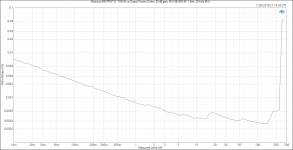
  • Ultra-low 0.00026 % THD+N (140 W, 8 ohm, 1 kHz).
  • Ultra-low 0.00029 % THD+N (260 W, 4 ohm, 1 kHz).
  • 16 uV RMS (A-weighted, 20 dB gain, 20 Hz - 20 kHz) output noise.
  • 1 kHz + 5.5 kHz IMD <-110 dBc @ 1 W.
  • Gain: +26 dB. Changeable by resistor option. Minimum gain: +20 dB.
  • On-board EMI/RFI input filter and ESD protection.
  • Power supply agnostic circuit architecture. The Modulus-686 performs identically on an unregulated supply as it does on a well-regulated supply.
  • Board dimensions: 8.25 x 2.30 inches (approx. 210 x 60 mm)
Full set of measurements found in Post #252 and Post #254. The transient response is shown in Post #331.

Also note that the Modulus-686 can be built for lower output power by lowering the supply voltage. For example, by running the Modulus-686 on ±27 V, it will provide 125 W into 8 Ω and 200 W into 4 Ω. Lower output power allows for a smaller heat sink. For a more comprehensive list of output power vs supply voltage, see Post #486.

It is always my goal to offer a positive build experience. Many businesses can deliver a good experience when all goes according to plan. In my view, examining the level of customer service when something doesn't go quite as planned is much more indicative of the quality of a business. Such an example is shown in Post #864. Note that all turned out well in the end. Also note the comparison of the Modulus-686 to a 12000 Euro (~$13600) commercially available amp towards the end of Post #864.

The Modulus-686 combines the learnings from the Modulus-86, -286, and some of the compensation tricks employed in the HP-1 to form a state of the art power amp. It is intended to operate from a +/-36 V supply and will provide the same stellar performance when powered by a switching supply as it does from a regular linear unregulated supply. A 
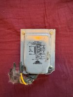
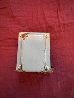
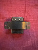
Power-86 with a 2x25 VAC, 500 VA transformer or a pair of Mean Well RPS-400-36 would work well for a mono MOD686 build. As seen in the third THD+N plot, the max output power is a little lower with the Power-86 as the rail voltage droops a little under load.

The Modulus-686 is currently available in two board options:
  • All surface mounted devices (SMD) pre-populated.
  • Fully assembled and tested amplifier module.
Update 2018/10/25: Do note that once the current board stock has sold, the SMD pre-populated option will be eliminated and I will only offer the fully assembled module option.
Unlike my past projects, I will not offer bare boards for sale. There are a couple of reasons for this:
  • Focusing on assembled and partially assembled modules allows me to lower the cost to everybody's benefit.
  • Supplying assembled and partially assembled boards allows me to serve my customers better and broaden my customer base.
  • Machine-soldered SMD boards perform much more consistently and reliably than hand soldered boards -- even for competent builders.
So basically, I can deliver a higher quality product by leaving the SMD assembly to the pros. This benefits everybody.

The full description of the Modulus-686 is available on its product description page: Neurochrome :: Modulus-686 :: 220W (8Ω); 380W (4Ω) @ 0.00026% THD+N.. A picture of the prototype is attached here.

The Modulus-686 circuit boards have arrived from the manufacturer. You can order yours here: https://www.neurochrome.com/product/modulus-686/

Thanks,

Tom

Attachments

  • Modulus-686 PROTO_ THD+N vs Output Power (8 ohm, 20 dB gain, MW SE-600-36, 1 kHz, 20 kHz BW).png
    Modulus-686 PROTO_ THD+N vs Output Power (8 ohm, 20 dB gain, MW SE-600-36, 1 kHz, 20 kHz BW).png
    50.8 KB · Views: 9,248
  • Modulus-686 PROTO_ THD+N vs Output Power (4 ohm, 20 dB gain, MW SE-600-36, 1 kHz, 20 kHz BW).png
    Modulus-686 PROTO_ THD+N vs Output Power (4 ohm, 20 dB gain, MW SE-600-36, 1 kHz, 20 kHz BW).png
    50.9 KB · Views: 8,679
  • Modulus-686 PROTO_ IMD 917 Hz + 5.5 kHz @ 1 W, 8 ohm.png
    Modulus-686 PROTO_ IMD 917 Hz + 5.5 kHz @ 1 W, 8 ohm.png
    39.6 KB · Views: 8,569
  • Modulus-686 PROTO_ THD+N vs Output Power, Power Supply (8 ohm, 1 kHz, 20 kHz BW).png
    Modulus-686 PROTO_ THD+N vs Output Power, Power Supply (8 ohm, 1 kHz, 20 kHz BW).png
    53.9 KB · Views: 8,956
  • MOD686_BlockDiagram.png
    MOD686_BlockDiagram.png
    158.9 KB · Views: 9,374
  • MOD686_Prototype.jpg
    MOD686_Prototype.jpg
    264.4 KB · Views: 4,556

(naïve) Question about this phase inverter circuit

Hi folks,

I'm an happy owner of this 2x5881 PP and I'm asking myself looking at the schematics about the phase inverter part of the circuit.
As I see it, it looks like a long tail pair circuit, but I don't get how the gain is leveled between the 2 outputs.
Most of the time, the gain difference is leveled via plate resistors, but there are the same, and there is this weird thing going to the grid of the second tube.
Please light me up on this !
Cheers

Attachments

  • ampli-hifi-tubes.jpg
    ampli-hifi-tubes.jpg
    116.2 KB · Views: 151

When I connect the Harman Kardon AVR265 HDMI 1 to the TV, the AVR detects an Fide TV, but the Harman Kardon AVR265 tV does not give the screen a menu

Hello, harman kardon avr265 avr anfide detects the tv when I connect hdmi 1 to the TV, but harman kardonavr265 does not give a menu to the screen, I could not solve this problem, I do not know where to look, what to control, I would be very happy if you could help me.

Reasons for torroid overheating

Hi.

After 20+ years of tampering with electronics (and getting an EE), I burned my first torroidial transformer!

The issue is that I dont understand why... The setup is 2 identical transformers with primaries in parrallel and secondaries in series.
Its powering a active subwoofer (300-400W classD and in THAM10).
All voltages check out and the setup was working fine for hours with minimal heat.

After the initial test the sub was stored in the basement for a few months and when I took it out for a test one of the transformers started smoking and melted the insulation within 2 minutes. I tuned off power as soon as I detected the fault.
The other transformer appears to be fine. Pretty sure that there is not an overload from the amplifier.

After removing the transformer, it was clear that it had shifted slightly beacuse the mounting pads had also melted somewhat.
I can understand that heavy vibration and melting mounting pads is an recipe for disaster, but Im not sure on the root cause.

One possibility is that I did not thighten the mounting bolt enough. - or maybe too much? - but Im pretty sure both transformers were mounted OK.

Any ideas? how would you secure a torroidial used in a sub? I´ve seen in commercial subs, so I assume its acceptable.

Kind regards TroelsM

Tubelab TSE-II with 45 tubes- One fully functioning and one bare PCB

SOLD. Thank you


Included in this sale is one bare TSE-II pcb, and one fully built and functioning 45 tube amp built with a Tubelab TSE-II pcb. Includes one Silvertone 45 tube, one National Union 45 tube, two Raytheon JAN 5642 tubes, one RCA 5U4G, one TEMco CBB65-R Run Capacitor, one Triad C-14X transformer, two Electraprint output transformers, and one Hammond 270FX power transformer.

The working TSE-II pcb was assembled by me in 2020, prior to my retirement. I called Jack Eliano at the former Electraprint shop and asked him to sell me the two output transformers for a 45 tube amp. I think they were $120 each, 5K:8 Ohm. Also, having a now retired former accountant wife, I always had to hide the true cost of items I bought in order to stay within my budget. 😉

All tubes were tested with my formerly owned Hickok Tube Tester and tested as NOS for all tubes. The working amp was assembled, bias adjusted and sounded really nice. I have the receipts for all the components, the total was ~$105. A 5U4G tube is well over $150 from Tube Depot, and a good pair of 45 tubes ain't cheap. Neither are the 5642 tubes.

I am asking for $600, or best offer for everything shown here. What you see is what you get.

IMG_2061.JPG


IMG_2079.JPG


IMG_2075.JPG


IMG_2080.JPG


IMG_2070.JPG


IMG_2071.JPG

SSE Red plating and Blowing Fuse

Good evening,

I have an SSE that is about 6 years old now. Recently it started red plating one power tube, does not take very long after turning on to blow the fuse. I have tried the obvious things such as a new tube, put in a new coupling cap, and replaced the bias resistor. Unfortunately it is difficult to get readings with the multimeter because the fuse blows pretty quick after start up, maybe 15-20 seconds if cold. Any suggestions of possible causes are greatly appreciated, thanks!

Old FANE driver

Hey guys,

I've visited an old Hifi buddy and listened to his new open baffle project with old Fane drivers. I liked the sound and would like to copy that project but the driver seems to be a phantom. I've searched the "whole internet" and couldn't find any information on this driver.. let alone a sales offer.
It's a 12" driver and I think it must be from the 70s (the man. date says something different but I think this is just the serial number)
Here are some pics:

PXL_20250207_151736357.jpg


PXL_20250207_151707948~2.jpg


I don't have a pic from the front but it has a whizzer cone.
Does anybody know anything about this driver? Especially where it was mounted? Guitar amps? Organs?

I really would love to rebuild the project so any help is highly appreciated!

Greetings
Tim

Lower My B+ Help

I built a clone fi SET amp last summer and I am primarily using 2A3 tubes. With Don’s original design one could use 2A3’s or 45’s but when using the 45’s you have to use a 5Y3 to lower the voltages. I’m using a 5U4GB with my 2A3’s safety within spec but when using the 45/5Y3 I’m at the hairy edge with the following numbers: plate voltage 237VDC, 47mA, plate disposition 11.3W. Is there an easy why to lower my B+ as to get in line with the 45 specs?

Choked Singing Bush ..... special one for Purists and Masochists

OK, this one long in making
I mean - have pcb files and everything for some time, basic functions confirmed but - as is my nature - never working by plan :rofl:

Anyway - why Purists and Masochists?

List of reasons:

1. you really need properly made high quality choke; 100mH, no more than 0R5 winding resistance, declared for 3A5dc (big Tokin) or 2A5dc (small Tokin)

2. PSU - bummer - heavy filtration; CLC, or C then cap multiplier followed with heacy C cell, or fat switcher ..... most likely also followed (by choice or necessity) with some sort of high-pass filter and followed with fat C cell

3. this time ( even if evidently intended as option) - no Schade Mos Puck; simply too high Rout of part itself (even if normally or even heavy Schaded), resulting in uberfunny transfer function and THD way too high; now - with all my crummy chokes (yes, Plethora of them but all crummy) that's the situation; there is a possibility that Schaded option is viable and worthy if adequate quality choke is used, but that I can't confirm, nor I intend to purchase it, in any way or arrangement

4. looking at all above - simply - cost; you gain something with lesser volts involved (vs. say "regular" Singing Bush) thus lesser heat and lesser Donut and lesser voltage caps and lesser Aluminum in sinks...... but then main choke, PSU choke, yadayada....

5. yes, OPT is an option, for both shown iteration ( Big Tokin, small Tokin), don't have it, easy to try if you have one; same conditions as with choke - do not even try with cheaply made Iron

there are few more reasons, worthy of this list, but I'm lazy to think now .....

Anyway, usual set of introductory eye-pleasing files:

Attachments

  • Choked Singing Bush Eagle sshot.png
    Choked Singing Bush Eagle sshot.png
    49.9 KB · Views: 1,207
  • Choked Singing Bush top render.png
    Choked Singing Bush top render.png
    1.1 MB · Views: 516
  • Choked Singing Bush bottom render.png
    Choked Singing Bush bottom render.png
    875.4 KB · Views: 1,180
  • Choked Singing Bush schmtc.png
    Choked Singing Bush schmtc.png
    352.8 KB · Views: 1,204

For Sale Keysight DSOX 1102G 2 channel 70 mHz 2 channel oscilloscope, built in Waveform Generator

Asking $500 including USA shipping. Payment by Zelle or Paypal. SOLD

I am the second owner of this Keysight oscilloscope. No functional problems that I have noted.

2 channel with built in function generator. Can easily do Bode plots.

Comes with the 2 standard probes as shown, a few extra cables, and a basic power cord.

No original packaging, but it will be carefully packed surrounded by rigid foam board.

I have the manual as a pdf I will send to the new owner.

USA shipping only.

IMG_1873.jpegIMG_1875.jpegIMG_1876.jpegIMG_1877.jpegIMG_1878.jpegIMG_1880.jpegIMG_1881.jpegIMG_1882.jpegIMG_1883.jpegIMG_1885.jpeg

The Well synchronized asynchronous FIFO buffer - Slaved I2S reclocker

Since the latch signal is crucial to get the best performance from a DAC we are developing a FIFO re-clocker that runs slave to the master clock.

In other words the FIFO buffer and re-clocker FPGA based does not manage the latch of the DAC (WS signal in I2S format and LLLR in PCM format) that comes directly from the master clock via a programmable divider isolated from the other digital circuits.
This to avoid any interference between the FPGA based digital circuit and the conversion circuit inside the DAC.

Every time the latch signal switches new data are asked to the FPGA, using all optical isolated lines.
This is a different approach in respect to other similar devices where the FPGA works on all I2S signals including the word select.

There will be 3 boards, the main FIFO re-clocker and the optional User Interface and Output Interface boards.

The main board has 4 I2S input selectable by the User Interface board.
Also the dithering process is selectable via the User Interface board.

There are 2 output options, both with header and u.fl connectors.
The main board needs 2 master clock signals, one for each sample rate family.
It can accommodate the Crystek or NDK oscillators, but a pair of very low phase noise are strongly suggested (5.6448 MHz up to 24.576 MHz).

More infos next days, a prototype is on the way.

New RPI Interface, LVDS transmitter and receiver I2S over HDMI from post #125
The Well synchronized asynchronous FIFO buffer - Slaved I2S reclocker

User manuals at post #153
The Well synchronized asynchronous FIFO buffer - Slaved I2S reclocker

Attachments

  • TWSAFB.jpg
    TWSAFB.jpg
    211.7 KB · Views: 3,650
  • TWSAFB-UI.jpg
    TWSAFB-UI.jpg
    146.3 KB · Views: 3,563
  • TWSAFB-OI.jpg
    TWSAFB-OI.jpg
    123.1 KB · Views: 3,503

Behringer CX2310 high noise levels, replace op amps?

Just got one of these and the noise levels are relatively high, its clearly audible from a few meters away with 85dB/1W/1M speakers. The original op amps are the 4580 as buffers and the 2060 for the filters, see partial schematic below. I have checked the power-supply to the op amps and its as clean as it gets with 7815/7915 regulators.
I am considering changing the 4580/2060 for the OPA165x Op Amps to get the noise levels down, any thoughts or other suggestions on this from anyone?
X-Pro schematic partial.JPG

For Sale Power Transformer, Filament Transformer, Chokes Hoard

I have the following power transformers, filament transformers, and chokes for sale. These were acquired over the years on eBay—some were used temporarily, while others remained unused.

I will add more items as I continue to sort through my collection.

Pricing: All prices are net to me. Please add shipping costs from Brooklyn, NY 11211, and 3% fees if paying via PayPal (as a purchase) or Venmo (as a purchase). No fees are required if paying via PayPal (as a friend), Venmo (as a friend), Zelle, or bank transfer.


Power Transformers:
  • Freed 29856 (Potted)
    750VCT @ 85mA, 5V @ 2A, 6.3V @ 2.75A
    Painted Black
    $40
  • Triad R-18A
    Primary: 115V
    Secondary: 750V CT @ 175mA, 6.3V CT @ 8A, 5V @ 3A
    $100
  • Triad R-116A (Full-wave)
    Primary: 117V
    Secondary: 700V CT @ 160mA, 6.3V @ 5A CT, 5V @ 3A
    Has scratches
    $50
  • Bendix Aviation L217151-1
    Plate Transformer
    $15


Chokes:

  • Freed 36856 (Potted)
    6H @ 85mA
    Painted Black
    $20
  • Tango 110
    10H @ 100mA
    $30
  • Sansui C-905
    10H @ 150mA
    $35
  • Bendix Aviation L217386-1 (Potted)
    10H @ 100ADC (or possibly 150ADC?)
    $15


Filament Transformers:

  • Standard Transformer P-3026
    Primary: 107-117V
    Secondary: 5V @ 3A CT
    $30
  • Peerless Electrical Pepco 1040
    6.3V
    $25
    I may still have the original box

Attachments

  • IMG_1642.jpeg
    IMG_1642.jpeg
    409.4 KB · Views: 31
  • IMG_1643.jpeg
    IMG_1643.jpeg
    369.9 KB · Views: 31
  • IMG_1644.jpeg
    IMG_1644.jpeg
    412.7 KB · Views: 31
  • IMG_1645.jpeg
    IMG_1645.jpeg
    345.2 KB · Views: 29
  • IMG_1646.jpeg
    IMG_1646.jpeg
    463.6 KB · Views: 30
  • IMG_1647.jpeg
    IMG_1647.jpeg
    383.5 KB · Views: 31
  • IMG_1648.jpeg
    IMG_1648.jpeg
    436.2 KB · Views: 30
  • IMG_1649.jpeg
    IMG_1649.jpeg
    444.2 KB · Views: 27
  • IMG_1650.jpeg
    IMG_1650.jpeg
    529.3 KB · Views: 30
  • IMG_1651.jpeg
    IMG_1651.jpeg
    546.4 KB · Views: 33
  • IMG_1652.jpeg
    IMG_1652.jpeg
    548.2 KB · Views: 36
  • IMG_1654.jpeg
    IMG_1654.jpeg
    467.6 KB · Views: 34
  • IMG_1655.jpeg
    IMG_1655.jpeg
    501 KB · Views: 36
  • IMG_1656.jpeg
    IMG_1656.jpeg
    582.9 KB · Views: 33
  • IMG_1657.jpeg
    IMG_1657.jpeg
    520 KB · Views: 28
  • IMG_1658.jpeg
    IMG_1658.jpeg
    430.4 KB · Views: 31
  • IMG_1659.jpeg
    IMG_1659.jpeg
    482.9 KB · Views: 27
  • IMG_1660.jpeg
    IMG_1660.jpeg
    852.2 KB · Views: 31
  • IMG_1661.jpeg
    IMG_1661.jpeg
    679 KB · Views: 34

Which system you would consider the best for specific genre of music ?

I did not found this topic so I hope it was not discussed somewhere, but I would like to know opinions (because this is what they are i am not trying to find the BEST) about from own experiences what system you would recommand for specific kind of music.
For example which speaker design for :

CLASSICAL CHAMBER MUSIC
BIG ORCHESTRA
JAZZ
BLUES
HEAVY METAL
PUNK ROCK/HARDCORE
POP
FOLK
LATIN
ELECTRO
HIPHOP
CHORUS

I tried to cover style by frequencies i am open to changes. Mono vs Stereo can also be in the answers, but it's not the main point. There will be a full rangef against multi way but even in multi way there will be sub genre as there is sub genre in music.

For example as my nickname suggest in this forum, I have been in love with listening to Time out Take five with caisson RJ from supravox. I will not state it is the best, but the overall listening experience is fantastic for me (this picture is not from me).

Time+Out-403762129.jpg
RJ.jpg
  • Like
Reactions: limono

End Game Array V2

messed up the title - it was supposed to say " please critique this " like the original thread.

it became obvious to me that i can completely eliminate one of 5 frequency bands from original design without much detriment so i did. here is the new design ( this is a horizontal cross section / view of array from the top ). the top of image is a waveguide that is forward facing towards the listener. the bottom of the image is a rear-firing subwoofer.

array sketch crop v2.jpg


for reference here is the original thread when the design was 5 way, which is embarrassing now because of how much more complex and expensive it was for almost no benefit:


but that thread has a lot of information about what i am trying to accomplish with that design so i am including a link to it.

basically all the drivers remain the same except that 12" woofers are eliminated. previously they covered 60 hz to 150 hz range but now the 18" subs simply go up to 120 hz and the 5" midbass array stretches a bit lower to 120 vs 150 hz.

there was originally a purpose to 12" woofers a few design iterations back but they lost their usefulness over several redesigns so now they're gone.

Some quick questions on Zen Decware EL84 SET schematic

I noticed I have all the parts to make this Zen Decware EL84/6BQ5/6P15P amp. I have a few quick questions about some possible improvements, opinions welcome. I want to make this a fast-build project so I'm not looking to depart too much or start all over from first-principles. Just what would be some good tweaks, if anyone wants to chime in. Schematic attached. Here are my questions:

1) Both the L/R output tubes are biased on the same cathode resistor, I assume its probably better for me to use two 75 ohom resistors instead of the single 150 ohm.

2) There doesnt seem to be a whole lot of capacitance in the reservoir and smoothing caps (only 33uf per). I have some 60uf motor run caps that I was thinking of using instead, go all-film since the designer didnt call for much capacitance in this design.

3) There seems to be a weird voltage divider dual capacitor decoupler (3.3 uf caps) for the 6N1P plates. What is that all about? I'll keep it I guess and I have some 5 uf motor run caps for these too.

4) The tranny voltage is 300-0-300 volts is this about right? does the operating point look ok overall at this voltage?

I'll be using this low-watts amp with a pair of Klipsch RP600M speakers (96db at 2.83V / 1m) and an 8 inch powered sub woofer coming off the speakers.

https://f072605def1c9a5ef179-a0bc3f...product-specsheets/RP-600M_Spec-Sheet_v01.pdf

Attachments

Crossover Recommendations for a Small Subwoofer

Hello,
I have two Tectonic TEBM65C20F-8 3-1/2" BMR Full-Range Speaker 8 Ohm speakers I want to supplement with a Tang Band W5-1138SMF 5-1/4" Paper Cone Subwoofer Speaker to add more bass response. I plan to put all three in a three chambered enclosure for use in a bedroom/office setting. I'm looking for a suitable preassembled crossover that will work for this pairing. I would like the crossover frequency to be around 200 Hz - 300 Hz based on the various speaker specs and modeling curves. The FR speakers are 8 Ohm, and the subwoofer is 4 Ohm.

I'm considering using a Parts Express 100 Hz Low Pass 8 Ohm Crossover Part #266-446. This is an 8 Ohm crossover. If I use two of these crossovers with that subwoofer (one for each FR speaker), can I reasonably expect the crossover frequency to increase from 100 Hz to somewhere near my desired 200-300 Hz? Are there any concerns to consider about doing this?

Recommendations for something else to consider are appreciated.

Thanks.

100 Hz Crossover
TEBM65C20F-8
W5-1138SMF

SMPS Noise and Ground Loop Issues with JLH Amplifier – Need Filter Advice

Hi everyone,

I am building a 4-channel JLH amplifier powered by a 24V Meanwell LRS-150-24 SMPS for a FAST system (2x SB34NRX75-6 woofers and 2x 4-inch full-range speakers). However, I am experiencing high-frequency switching noise and ground loop issues.

While searching for solutions, I came across two different SMPS DC filters on DIYAudio:

  1. ACA Power Supply Filter
  2. PO89ZB Filter
I noticed that these two filters use very different inductor values. One has 2.2µH, while the other uses 180µH. I’m trying to understand why there is such a big difference and which one would be more suitable for my JLH amplifiers.

I also have 10pcs of white and yellow toroidal cores that, as I recall, produce 100µH with 22 turns. Can I use these for an SMPS DC filter? Additionally, I have some 27µH (13x13mm green) inductors.

Would these components be useful for reducing switching noise and ground loop issues? I also have many different capacitors to make pi filters.Any advice, filter schematics, or suggestions would be greatly appreciated!

Thanks in advance!

Attachments

  • 20250228_233032.jpg
    20250228_233032.jpg
    654.3 KB · Views: 41
  • 20250228_232811.jpg
    20250228_232811.jpg
    462.7 KB · Views: 40

Paper capacitors?

I got 10 of these 5nF capacitors very cheap:
capacitor.jpg

It says 'DIN41161' and if I look that up I see it is a 'paper capacitor'.
They must be very old, however the first two measure ok, didn't check them all. And they do not seem to be used.
Are they still usable for audio? How is the quality of a paper capacitor compared to say, a film capacitor?

Tweaking sound Funkey RP-88A Rollpiano

A little tweak to a mobile electric piano brings a better sound to it:

The small loudspeaker got some papercone treatment with thin silicone sealant omitting the dustcap.

One ohm put in line made it sound less aggressive and more pleasing (adding a little bit of current drive to the amplifier)

The sound got much nicer and more articulate!

images-12.jpeg


IMG_20250228_073432.jpg


IMG_20250228_073254.jpg


Disassembling is easy only remove six screws.

loudspeaker is easy removable

And put all back again after tuning / tweaking the electric piano.

Here some fotos of the inside electronics

IMG_20250228_073403.jpg


IMG_20250228_073351.jpg

IMG_20250228_073307.jpg

Turntable Pioneer revisioned

good morning, I was given an old Pioneer turntable, on which I replaced the belt, cartridge/stylus (I put an AT VM95H) and created an external power supply. I would need documentation with clear suggestions to do best complete setup of it: set height, cartridge/stylus alignment etc... Furthermore, I would need a sheet drawn with the stroboscope, that I can download and print 1/1 to place it on the plate for turns number adjust . I apologize in advance if the topic has already been discussed, but I haven't found anything yet (if so, can you provide me with the link). Thank you. Kind regards and the entire forum. Ros

GRS vs Fountek vs Aurum Cantus vs RAAL

first off i have never heard a ribbon tweeter in my life so this is just my take based on research i was able to do online and i may be wrong, but this is what it looks like to me:

GRS: seems to be fake Fountek, or at least an el cheapo version of it - probably made in the same factory, but with smaller magnets and regular aluminum ribbon ( not sandwich ). the foil is also very thick. efficiency is low for a pure aluminum ribbon.

Fountek: decent ribbon but spotty availability and it is more than a little bit concerning that manufacturer doesn't even have a website. the housing is made of plastic such that for example the front bezel screws into plastic and the "fins" on top and bottom that hold the ribbon also attach to plastic. not very nice.

i feel like the cheap plastic build of Fountek is appropriate at GRS price point ( which uses the same build ) but not at Fountek's price point. you do get bigger magnets in Fountek and it is unclear what kind of ribbon element you get.

Aurum Cantus: 50% heavier than Fountek because it uses no plastic and magnetic return structure is cast iron, not stamped steel. also because plastic is eliminated it has smaller exterior dimensions for same ribbon size, which is beneficial for line arrays maintaining tighter gaps between ribbons. 100db effcient. replacement ribbons sold through PE.

RAAL: very fancy and expensive. you can buy an entire GRS driver for the price of RAAL replacement ribbon. made in Europe. all the other ribbons mentioned above are made in China.

to me personally i think Aurum Cantus is the sweet spot. all metal construction and cheap replacement ribbons.

but ironically Aurum Cantus seems to be the least talked about out of the four ... any ideas why ?

Tektronix 577 D1 curve tracer intensity malfunction

Hi and thank you for the forum!
I bought this equipment a week ago and it was quite OK when I did resistor, capacitor and diode measurement (user manual). anyway, it didn't go so well when you wanted to check the characteristics of a transistor.
I decided to go through the calibration according to the service manual and this is where I ran into problems. I tried doing point 4 "adjust intensity range" INT RANGE potentiometer (R1245) rotated sluggishly so I sprayed it with some electric lubricant (see picture) then when I started again, the intensity knob no longer worked. I checked the service manual again and drawing 8 (see attached picture) and discovered that the resistor R1236 had browned. I changed it and then this browned again. I did ohm measurement on R1245 mounted on PCB and it varies between 0 and 1Mohm so I don't think the problem lies here. I suspect that it lies in the Z-Axis amplifier and the part that ensures that there is a constant current flow throw this operational amp. In other words, I suspect that C1236 or Q1234 are the culprits. What do you think? any advice can be of great help. It is quite difficult to pick out the whole CRT Circuit PCB and don't want to do it unless absolutely is necessary.
Another solution that I wanted to try is to isolate the board from all the remaining parts and apply power only to the yellow part of the drawing (External +30, -30VDC and 200VDC) via P1130, then inject a square wave (20Vp-p) on the anode part of CR1209 and see what the OSC have to say in the collector part of Q1226 if it looks like on the graph. What do you think? Transformer T1240 is powerless so there shouldn't be a mega-voltage out to the CRT (-3450V) right?
thanks!

Attachments

  • 2-26.jpg
    2-26.jpg
    52.3 KB · Views: 55
  • Intensity malfunction_1.png
    Intensity malfunction_1.png
    848.6 KB · Views: 58
  • thumbnail_IMG_6902.jpg
    thumbnail_IMG_6902.jpg
    58.4 KB · Views: 52

Is this a case of noise or oscillation? How critical is the impact of this signal anomaly

Greetings! I am building a GFA-565 amplifier, and the signal shown in the image is present at the amplifier's output. How much of an issue could this be for sound quality? Is it worth addressing this problem? Note that the amplifier is not yet installed in its case. The oscilloscope is set to 0.2 µs/div, 50 mV/div, and x1 probe position. The signal at the amplifier's output is approximately 20 MHz with an amplitude of 50 mV.

Attachments

  • Osc1.jpg
    Osc1.jpg
    118.5 KB · Views: 120

Centure 24: digital 4-Channel DSP Amplifier with Class-H option

Hello DIYAudio community,

Couple of years ago I’ve designed a DSP Class-D amplifier called Centure 21. It has got ADAU1452 DSP, TAS5548 as I2S->PWM modulator and 4 output channels, with 4 more available on the "PWM" header.

and photo of the prototype:
1734794922830.png


on the left there is Amanero header, which can be used for amanero module to have just USB 2 ch input, or my York interface. There was also header on the left side with S/PDIF and I2S which are connected to ADAU1452. The purpose is to connect daugter boards with different input interfaces: ADC, AES/EBU, TOSLINK etc. The module was used primarily for home audio.

After some discussion here on DIYaudio with @florentg (https://www.diyaudio.com/community/...-dsp-bluetooth-aux.376006/page-2#post-7719605) we meet in person played with the Centure 21 and discussed what we could do in the field of DSP amps, the specs and software and ways to build something better. Recently TI announced a new amplifier IC TAS6584 which basically combines I2S→PWM modulator and the output stage but also have some quite interesting features, like the H-Class power supply control.

So a new device was developed 🙂

Structure of Centure 24:
image (1).png


The structure of new version is quite similar to previous one: there is DC-DC for output stages, a DSP chip and MCU to control and monitor the system. The main difference is in more advanced diagnostic and monitoring of the sysem, thanks to TAS6584. Also since TAS6584 implement H-Class control together with the DC-DC, this fetature is also available and can be enabled/disabled via software. Here is demo from TI: https://www.ti.com/video/6287333584001

photo_2024-12-20_19-34-06-removebg (1).png


This time the module designed such that it can be also used as the plate amp: all the interfaces (S/PDIF, I2S, I2C) are routed to headers and supposed to be connected to interface board (which is not ready yet):

plate.png


The amplifier has 4 channels which can be configured as 4xBTL, 2XBTL + PBTL or 2xPBTL. So it allows fleaxible configuration for multiway systems. The nominal output power would be around 200W for all channels combined, the peak power of course would be higher. Not all measurements are done, only up to 100W/channel.

There is also software development going on which is based on the York interface (thread on DIYaudio: https://www.diyaudio.com/community/...tichannel-input-output-interface-york.413504/)

image (2).png


Live monitor of Class-H operation:

image (3).png


Measurements, experiments with the H-Class control and config software features will be posted later.

For Sale Hashimoto PT-150F power trans., HC-203U 2.5K/3.5K SE OPT pair

Hi all,

Hashimoto transformers, brand new and unused.

1x PT-150F power transformer:
Pri: 120V
Sec:
  • 280V-250V-220V-0V-220V-250V-280V-160mA AC (220mA DC: double wave rectification)
  • 0V-6.3V-2A (3 circuits)
  • 0V-5V-3A

HC-203U pair
Output: 20W at 50Hz
Primary: 2.5K or 3.5K Ohms
Secondary: 4, 8, 16 Ohms
FR(+-2dB) 30-60,000Hz
Suitable for 300B, EL-34, 2A3, 6GB4, 6L6-GC, 6A3


Asking $720 shipped CONUS. (roughly 10-15% off cost of new price)

Attachments

  • P1040772.jpg
    P1040772.jpg
    269.9 KB · Views: 61
  • P1040773.jpg
    P1040773.jpg
    235.4 KB · Views: 57

Dayton Audio CE32A-4 (1-1/4" Mini Speaker, 4 Ohm)

I installed the Dayton Audio CE32A-4 in a mini-sized bass reflex enclosure.
The finish is vinyl sheet.

HB-02F-01.jpg


It doesn't produce low frequencies, but it delivers a lovely female vocal performance.
Truly the "Songstress of the Dwarf Kingdom."
It may not be considered a full-range speaker, but it is sufficient to enjoy on its own.

Login to view embedded media

Attachments

  • HB-02F-03.jpg
    HB-02F-03.jpg
    172.4 KB · Views: 224
  • HB-02F-05.jpg
    HB-02F-05.jpg
    155.1 KB · Views: 220
  • HB-02F-04.jpg
    HB-02F-04.jpg
    185.5 KB · Views: 218
  • HB-02F-06.jpg
    HB-02F-06.jpg
    174 KB · Views: 267
  • HB-02F-07.jpg
    HB-02F-07.jpg
    195 KB · Views: 391

For Sale I2SoverUSB v.III and oscillator board and crystek clocks

Jlsounds I2SoverUSB v.III board
Oscillator board with crystek CCHD-957-25-45.1584 and CCHD-957-25-49.152 oscillators
And I have a couple power supply boards that go with it. 5V and a 4.2V made with LM317 and LM1117. You will just need to supply 7-12VAC input power.

I soldered a 9 pin molex header onto H3 on the oscillator board so you can connect to the I2S pins.

$100. you pay shipping.


SOLD


IMG_1529.jpgIMG_1524.jpgIMG_1525.jpgIMG_1526.jpgIMG_1527.jpg
Projects by fanatics, for fanatics
Get answers and advice for everyone wanting to learn the art of audio.
Join the Community
507,365
Members
7,867,275
Messages

Filter

Forum Statistics

Threads
405,235
Messages
7,867,275
Members
507,365
Latest member
Chandena