You are using an out of date browser. It may not display this or other websites correctly.
You should upgrade or use an alternative browser.
You should upgrade or use an alternative browser.
Filters
Show only:


is this can be horned?
can this driver be horned?
what size horn it should be?
i have no pc,only handphone,so i can't run any horn program
what size horn it should be?
i have no pc,only handphone,so i can't run any horn program
Attachments


Attentuation circuit
- By loddie
- Construction Tips
- 39 Replies
I plan to build an passive attenuator to step down multiple identical audio sources (Class D amplifiers rated 3W@4-32 Ohms) to multiple sound card inputs +4dBu (MOTU 2408 MKII duplex sound card). Each source will go to a dedicated input channel on the MOTU sound card and thus it is my understanding this creates challenges due to summing of differential Class D voltages (compared to just a single source). The goal is to preserve sound quality as reasonably as possible and as tactile transducers rate to 12 Hz will be used, maintain source bass signals below 20 Hz. Also, the source signals will be summed in a VST host in various combinations (e.g., 3 sources may be summed to 1 output channel with another 2 sources into a different output channel). As electronic circuits are not my strength, I have multiple newbie questions:
1. The source volume can be adjusted. However, the listening volume will always be adjusted after the sound card. What level should the source volume be set at to maximize sound quality (S/N ratio/distortion)? I assume maximum volume, but perhaps when considering the interaction with the passive attenuator, a lower source output may be appropriate. Also, as the sources are Class D amps, perhaps there is an optimal volume level which has less distortion. It seems determining the volume level is important as it will change the attenuationl level needed and the component values (e.g., resistor Ohms rating).
2. What type of passive attenuator is ideal for this application? As bass/subsonic signals are desired, audio transformers are not ideal due to bass frequency loss and the cost of quality audio transformers which preserve bass signals is prohibitive with planned channel expansion (up to 40 mono sources). Thus, it seems that voltage dividers/"pads" such as L-Pads, Pi-pads, T-pads, etc. are the ideal solution considering compromises of cost vs. sound quality. However, in reading about the various voltage divider configurations, it is not obvious which voltage divider designs are suited for which applications, particularly this one.
3. Related to question #2 above, the impedance of the source and sound card are likely mismatched (I'm struggling to relate the amp Watts output to sound card dBu input). Some authors mention the voltage divider source and output impedances can be matched, but not for both impedances. Does this matter in an audio application? If so, then it seems some voltage divider arrangements are not appropriate and only designs in which the impedances are matched both directions should be used.
4. Some voltage dividers are unbalanced while others are balanced. Is either unbalanced or balanced preferred for audio applications?
5. Does the "balanced" aspect of a balanced voltage divider have any relation to "balanced" audio signals (e.g., XLR cables)? Edit: I forgot to mention that the Motu can receive a balanced (1/4" TRS plug) or unbalanced signal (1/4" TS plug).
6. The MOTU 2408 MKII sound card is DC coupled which may cause a DC offset. While I understand how the value of a DC blocking capacitor is determined [Xc(ohms) = 1/(2*3.14*f*C)], it is not clear where the capacitor should be place in a voltage divider. Does it matter if it is placed before or after R1 (or somewhere else)?
7. As the Class D amplifier sources have an unknown high switching frequency, should a low pass filter also be added to the voltage dividers? If so, it is not clear where the capacitor should go in a voltage divider. Does it matter if it is placed before or after R1 (or somewhere else)?
I try to learn as much as possible before posting, but as after many hours of studying, I'm not making much progress. It seems that much of audio involves rules of thumb known by those in the art and many educational articles do not directly related to audio or sound quality. Attached is the project with the areas of concern in red.
Attachments

Woden Design Kongo build
- By SonocusEric
- Full Range
- 9 Replies
Im planning on building the kongo horns for my small studio and have couple of questions-
1. What other drivers could be used for this design? Im hoping for something cheaper that i could buy from partsexpress.
2. Is the plan available in metric system too? I worry that im messing up the dimensions by only roughly following the metric units already on the document
1. What other drivers could be used for this design? Im hoping for something cheaper that i could buy from partsexpress.
2. Is the plan available in metric system too? I worry that im messing up the dimensions by only roughly following the metric units already on the document
Attachments

Weird rectifier circuit with 2 diodes.
- By osci
- Tubes / Valves
- 33 Replies
Hi all, Its been around few years since I've posted here and I'm hoping some much more knowledgeable members can once again give me guidance.
I have a valve PA amp that's been sitting collecting dust and finally opened it up, There's no circuit diagram available so I will have to trace this out, I have no problems with everything after the rectifier circuit, However, The rectifier circuit does have me bemused.
I'm not an electronics tech, But I do have a very healthy respect for high voltage, The amp has 5 valves, 1 x EF86, 2 x 12AX7, 2 x EL34, I believe the rectifier circuit may be half wave? 'but its how the diodes are connected that has me confused' (I've attached a photo).
The AC input of neutral active & earth are not a problem, However, The Yellow wires in the photo are the high voltage secondary's with the green CT below the yellow wires soldered directly to ground.
One side of the high voltage secondary appears to be connected correctly through one diode to the first filter cap. The other half of the high voltage secondary is connected directly to the second pin of the first filter cap, The second diode has one leg connected directly to ground with the other leg connected to the first HV secondary mentioned above?
I can't wrap my head around this as to whether the rectifier circuit is a half wave or full wave rectifier circuit. The other colour wires coming out of the chassis are Blue = 6.3v heater, Green = CT for HV secondary, Brown = 240v mains in.
I've attached a photo of how the circuit is soldered in question
So my questions are
1 - Is the rectifier circuit half wave or full wave?
2 - How do I draw this out for schematic purposes, as I'm a bit dumbfounded by it?
other notes: I've not powered the amp up nor made any changes except cleaning off the build up of cobwebs and dust.
I hope someone can give me advice and guidance with this project.
cheers.
Attachments

Toroidal vs regular transformer punch?
- By purpo
- Tubes / Valves
- 84 Replies
Hi,
I watched a video today from Thomas and Stereo on Youtube and he mentioned something about transformers that I don't understand.
He said that regular transformers have more punch than toroidal transformers. I'm a beginner hobbyist but want to know other opinions.
Do toroidal transformers make music less "punchy" than regular transformers?
Thanks,
Dan.
Login to view embedded media

Krell KAV-250 250a 250a/3
- By Bigred777
- Solid State
- 4 Replies
I’m looking for a schematic for the KAV-250 and have come up empty handed. I did see a post from 2007 with a hand drawn schematic of the output board. That helps. But really need the driver board schematic. I have one channel that starts making static/popcorn sounds the second I power up the amp. I can see the noise on my scope right at the input of the amp as well as the output. Very hard to isolate. Any suggestions would be great.
100w PP EL34 amp repair help
- By Pauld35
- Instruments and Amps
- 9 Replies
Hi,
I Bought an amp that have just had the output transformer replaced. The owner said she used it once fine and then it started blowing fuses.
I set up a current limiter and everything started up fine after five minutes of playing without the limiter I got blue sparks through one of the power tubes and the slow blow fuse blew.
The PT and the OT are not original. I have sketch out the power supply So not sure of which windings are connected Because I haven’t disconnected.
I research as much as possible to could be bad tube Or loose socket Or poor OT connection or Intermittent voice coil problem.
*I notice when taking readings with no power tubes pin3 Create scratching sound in speaker.
*I test for vac on bias circuit. noticed 22 vac On negative bias Circuit Close to diode Then no vac 10mm up circuit futher , Only the -40vdc negative dc bias.
*I question the power supply. original schem. has a lot higher voltage730v vs 495vdc to OT primary centre tap (ht1 on schematic) than amp has now.
*the two 220k resistors Jumping the filter caps straight after the rectifier.
Any advice what to check for would be great thanks.
I have a pair spare El34, do not want to put them in in case the problem could be not just bad tube.
I will upload the schematics now, thanks
"The Wire" Official Boards for All Projects Available Here! BAL-BAL, SE-SE, LPUHP
- By opc
- Vendor's Bazaar
- 1083 Replies
"The Wire" Official Boards for All Projects Available Here! BAL-BAL, SE-SE, LPUHP
Hi Gentlemen,
Well, it has been a long wait (a very long wait for some of you) but all of my PCB’s from “The Wire” series have been updated and will be offered on a full time basis rather than on a limited run basis as they have been in the past.
This thread is going to cover the transition period between now (another Google Spreadsheet based order system) and the eventual launch of the website that will have a store where these can be purchased.
Over the next two weeks I’d like to get an idea of demand for each of the boards so I can place an order and panelize it accordingly. I will then place the board orders which will take 3 weeks to arrive at my doorstep. After that, I will need a week for testing, and then I will ship the first wave out and start taking real-time orders from then on while hopefully maintaining a proper stock of boards. Hopefully the website will be up and running not too long after I start taking real-time orders.
Please use the following Google Spreadsheet to place your orders:
the wire pcb order form - Google Sheets
What follows is the description and pricing for each of the boards that will be on offer. Pricing is slightly higher than before, but you’ll be getting better boards (modified to take advantage of all 4 layers) and ENIG immersion gold plating with tented vias for better solderability. Pricing is also more in-line with the actual surface area of the board, so smaller boards will see almost no price increase, while larger boards will see more of a price increase.
Without further ado:
“The Wire” BAL-BAL Headphone Amp ($17 for a single stereo board)
- Design altered slightly to include a 4th layer GND plane.
- 4 Layer PCB – 1oz copper – immersion gold plated – tented vias – white soldermask
- Improved headphone connection points
- Overall same size as predecessor
- Same schematic and BOM as predecessor
- See project thread here: http://www.diyaudio.com/forums/head...igh-performance-headphone-amplifier-pcbs.html
- See project wiki here: The Wire - All Boards and Kits Explained Here!
“The Wire” SE-SE Headphone Amp ($15 for a single stereo board)
- Design altered slightly to include a 4th layer GND plane.
- 4 Layer PCB – 1oz copper – immersion gold plated – tented vias – white soldermask
- Floating GND connection fixed
- Overall same size as predecessor
- Same schematic and BOM as predecessor
- See project thread here: http://www.diyaudio.com/forums/head...igh-performance-headphone-amplifier-pcbs.html
- See project wiki here: The Wire - All Boards and Kits Explained Here!
“The Wire” PSU for Headphone Amps ($15 for a single PSU board)
- 4 Layer PCB – 1oz copper – immersion gold plated – tented vias – white soldermask
- Slightly wider than predecessor
- Completely redesigned using dual TPS7A3301 (TO-220) ultra-low noise regulators.
- Now requires a transformer with dual secondaries. Centre tapped transformers will not work.
- Significant performance improvement from previous LM317/337 regulators.
- See new BOM here: https://docs.google.com/spreadsheet/ccc?key=0AnMLwB9mdXl2dDN6V05FanpQN1BFR2xRcENORVFSNXc&usp=sharing
- See new schematic here: https://drive.google.com/file/d/0B3MLwB9mdXl2Z3N4WWh4MU93SW8/edit?usp=sharing
- See project wiki here: The Wire - All Boards and Kits Explained Here!
“The Wire” LPUHP Amplifier ($28 for a single channel board)
- Design altered to include a 4th layer.
- Thermal vias added to allow simple heatsinking from bottom of PCB.
- 4 Layer PCB – 1oz copper – immersion gold plated – tented vias – white soldermask
- Transformer moved off-board for lower noise and compatibility with 120V/230V
- Regulator sections changed to use dual LT1185 low noise regulators.
- Measurable improvement in performance – noise floor is nearly 10dB better.
- See project thread here: http://www.diyaudio.com/forums/soli...gh-perfromance-lpuhp-16w-power-amplifier.html
- See new BOM here: https://docs.google.com/spreadsheet/ccc?key=0AnMLwB9mdXl2dDVuTjh6WnZmQ1VxYm1FVW9zRzRaMUE&usp=sharing
- See new schematic here: https://drive.google.com/file/d/0B3MLwB9mdXl2TnQ0Wjd2UUFMcDQ/edit?usp=sharing
- See project wiki here: The Wire - All Boards and Kits Explained Here!
“The Wire” LME49830 Lateral FET Power Amplifier ($17 for a single channel board)
- Design altered to include a 4th layer.
- 4 Layer PCB – 1oz copper – immersion gold plated – tented vias – white soldermask
- Identical to predecessor
- See project thread here: "The Wire AMP" Class A/AB Power Amplifier based on the LME49830 with Lateral Mosfets
- See assembly manual here: https://drive.google.com/file/d/0B3MLwB9mdXl2NVEwS1pwNVV0OG8/edit?usp=sharing
- See project wiki here: The Wire - All Boards and Kits Explained Here!
NTD1 PCB V3 - ($35 for a single stereo board with full PSU)
- 2 Layer PCB – 1oz copper – immersion gold plated – tented vias – white soldermask
- Designed to be used with BII, BIII and ACKO ESS9018 based DAC boards.
- Upgraded TPS7A3301 regulator section – Improved noise floor
- Same dimensions and mounting points as V2
- See project thread here: http://www.diyaudio.com/forums/digital-line-level/154866-new-take-classic-pass-labs-d1-ess-dac.html
- See project wiki here: The Wire - All Boards and Kits Explained Here!
Upcoming Boards:
- Behringer DCX2496 Upgrade Board - Digital, Analog, Clock and PSU sections.
- UHPSR - Ultra High Performance Shunt Regulator - Adjustable 1.1V to 5V
- HiFiduino all in one PCB – Arduino based controller and all peripherals on one PCB
- TPS7A4700 / TPS7A3301 Regulator PCB – LM fixed reg drop-in replacement
More info to follow, and the spreadsheet link will be posted in a few hours!
Cheers,
Owen
Two Ports Instead of One
I'm building a BR using Ampslab's recommended 25 liter enclosure with the Silver Flute W20RC38-08. He calls for a
2" diameter port 6 1/2" in length. My cabinet will be 9" deep or 7.5" internal. To leave plenty of clearance from the back wall can I use two 3 1/4" ports and accomplish what I need to? Thanks for any suggestions.
2" diameter port 6 1/2" in length. My cabinet will be 9" deep or 7.5" internal. To leave plenty of clearance from the back wall can I use two 3 1/4" ports and accomplish what I need to? Thanks for any suggestions.
Symmetric floating bench power supply tracking problem
- By Onemangang
- Power Supplies
- 4 Replies
Hi all.
I am in the process of designing my own fully symmetric bench power supply. It will go from 0 to around ± 70V @ 3 amps.
The voltage controls will be floating, while the current limiters probably will be in respect to true gnd of the main supply.
The whole thing will consist of 4 internal supplies to make it all work. 1x 75-0-75 and 3x 15-0-15 DC. One of the 15-0-15 will share gnd with the
75-0-75 main supply. The two others will be floating, which is where I am a bit lost.
I cant wrap my head around to to make the tracking work between the two floating supplies. The only thing I can think of is to
create some variable current sources in the common 15-0-15 supply, and pull that current through a resistor in the floating
supplies. That should work, but it somehow doesnt feel right.
I dont need mcu control or programmability. I just want to turn one reference voltage from true gnd into the same voltage on
each floating supply. I have thought about using a stereo pot for this, but the channels usually dont track too well on pots.
I also havent found any info on this, nor could I find any schematics on this issue.
Any insight on this is welcome
Thanks in advance
Jørgen
Attachments
Monitor Audio Silver 6 G5
Monitor Audio Silver 6 G5 crossover
Hi all,
I am just wondering if it make sense to upgrade the crossover of MA silver 6 G5 (to make the speakers level up), or did anyone here did some mod...or I should just leave it like it is... here is a pic of the crossover
Hi all,
I am just wondering if it make sense to upgrade the crossover of MA silver 6 G5 (to make the speakers level up), or did anyone here did some mod...or I should just leave it like it is... here is a pic of the crossover
Attachments

TU8200 - weird problem
Hi, wondering if someone can help solve a problem with the TU-8200 (earlier version).
About a year back I tried the 6P3S-e and while they sounded fine, the amp clearly was not pleased. Everything got really hot and ended up with weird buzzing noise. I replaced the mosfets Q1-Q4 and some of the problem went away.
Now, I have the strangest problem - even with the amp switched OFF I hear a slight buzz. The speakers are Altec with a fair bit of efficiency, but none of my other DIY amps have a similar problem. The buzz remains when playing music and gets louder with the volume control turned up. When switched off, the buzz is at a constant level and the volume control has no change. Any ideas would be really helpful, this thing is driving me NUTS.
Since THAT experiment I've stuck with G.E 6L6GC (tested on another amp). The only way to get rid of the buzz is unplugging the mains cord.
thanks,
Sunil
For Sale FS: PAIR of NEW One Electron UBT-3 OT, 3k to 4/8/16 ohm
- Swap Meet
- 1 Replies
I have a pair of One-Electron UBT-3 output transformers, 3000 to 4/8/16. These are new with full leads.
Located in St. Louis, Missouri, USA. $220.00 for the pair plus shipping.
.png")
Located in St. Louis, Missouri, USA. $220.00 for the pair plus shipping.
Attachments
Replacing 314 type ceramic fuse with regular fuse
- By qguy2000
- Solid State
- 2 Replies
My power amp stopped working, no sound, powers on, relays are clicking, but no sound. Started poking around and checked two 10a, 250v 314 ceramic type fuse. I only had regular fuse with the same 10 amp rating, I replaced it and the amp is now working again. Can I retain the regular fuse or should I replaced it with the ceramic type fuse?
First DIY Tube Kit Recommendations
- By sparton175
- Tubes / Valves
- 30 Replies
I've had the opportunity to pick up a few pairs of vintage speakers recently, Dynaco A-35s and Akai SW-180s. I'm enjoying them on my SS amps that I own now but I'm interested in trying speakers with some tubes. I currently have a DarkVoice for my headphones which I love but I'd like to try a stereo tube speaker amp. I've seen a number of kits out there for DIY tube amps but I'm not sure which one would be best for my application and price point. I'd like to use this with my record player and with my phone via either Bluetooth or RCA and I'd like the best kit I can buy for $300 or less shipped to the US. I don't need a headphone output for this amp and I don't need any crazy high wattages to drive these speakers.
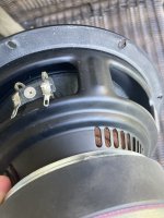
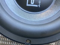
For Sale REL Acoustics T5 subwoofer driver (8 inch)
SOLD
Asking $179 per driver or $295 for both.
The drivers look new. They came out from REL T5 subwoofers that their amps didn’t power on. The amps have leaked caps and bad resistors. The amps are also for sale if you are interested.
I have two woofers/drivers for sale.
You get what you see in the photos.
No returns.
8in., 200 mm long-throw, steel chassis
P.S. If you look at the photos TOO CLOSELY, you see some stuff; they are FUZZ! I think from the carpet. There is ZERO scratch or anything like it on the driver itself.
Attachments
-
 E95844C0-2C82-497C-935A-B96ECB4C94E1.jpeg710.6 KB · Views: 196
 -
 EA81E9CF-2482-4087-A3FF-70245CE83319.jpeg320.6 KB · Views: 285
 -
 1E3D5CB3-F105-4BCF-8D6E-BFEF4D83CAAF.jpeg716.7 KB · Views: 382
 -
 CE4360A9-9388-4349-94A0-7209649AC28B.jpeg435.2 KB · Views: 300
 -
 892A9C39-F5DD-4369-9AC1-4DB1339F2991.jpeg331.5 KB · Views: 206
 -
 71E7D45B-E5A8-464A-994F-A0BB3248F95A.jpeg825.1 KB · Views: 272
 -
 E2E88A19-84C8-4123-9E91-08FA6E73AA23.jpeg646.4 KB · Views: 224
 -
 A67AE473-BE7A-4747-A983-5DE1279DC64D.jpeg322.1 KB · Views: 183
 -
 12AD471E-4FE2-4F56-B937-4AF0A346E37A.jpeg590.7 KB · Views: 182
 -
 9CEB3ED6-4482-481A-B528-D0E65B3FC62E.jpeg542.5 KB · Views: 205
 -
 F64410CA-0A06-450A-B790-51B74C317E97.jpeg421.9 KB · Views: 170
 -
 C13D00A6-FEE2-44AC-B33E-7985FA502C7C.jpeg357.9 KB · Views: 185
 -
 DA4C47C0-AF8D-47D4-8678-81EFAAABF0CD.jpeg472.8 KB · Views: 174
 -
 A8F4338B-4F8F-458C-8FCF-26B78F2B4E21.jpeg462.7 KB · Views: 170
PCB protective liquid
- By Pitrus
- Equipment & Tools
- 28 Replies
Hi all,
I would like some advice on which excellent spray product to use to protect the soldering side PCBs after having cleaned, degreased and removed the original protection applied by manufacturers on old pcb's.
I don't want to leave the pcb without any protection.
Thanks
I would like some advice on which excellent spray product to use to protect the soldering side PCBs after having cleaned, degreased and removed the original protection applied by manufacturers on old pcb's.
I don't want to leave the pcb without any protection.
Thanks
Technics SU 8600 protect problem.
- By Lynyrd
- Solid State
- 32 Replies
Hello.
Its strange problem of protect mode on TECHNICS SU 8600 Amplifier.
If I desoldered TR506 relay click,and Amplifier works fine.
With TR506 relay not click.
All voltages are ok.
No DC voltage on speakers terminals.
Amplifier works fine without TR506....
THANKS
Its strange problem of protect mode on TECHNICS SU 8600 Amplifier.
If I desoldered TR506 relay click,and Amplifier works fine.
With TR506 relay not click.
All voltages are ok.
No DC voltage on speakers terminals.
Amplifier works fine without TR506....
THANKS
Attachments

digidesign 442 I/O as standalone DAC for S/PDIF transport
- Digital Source
- 44 Replies
Hi,
I've been given a Digidesign 442 audio interface box - the Nubus Mac and controller card is long gone.
Rather than put this into landfill as toxic waste, I was wondering whether anyone has any experience of getting these units to 'free-run' as DAC boxes - taking S/PDIF from the RCA input jack and putting the analog audio out of the XLR connectors.
The S/PDIF decoder is the Crystal Semi CS8412
The DAC/filter pair is AD1860/NPC SM5813
I've found datasheets for the CS8412 and AD186x - no luck at NPC.co.jp for the digital filter, sadly.
I've tried feeding 2-channel 44kHz PCM from my CD player into the S/PDIF input to see if the box has any autonomous capability - but it stays stuck on AES/EBU 48kHz :-(
Opinions about the practicality of this project welcome !
For Sale Set of three power supply PCBs
- By mattattnet
- Swap Meet
- 2 Replies
SOLD
Set of 3 various power supply boards from an overseas supplier. All can be used for various Class A amplifier needs.
Asking $20 including Continental USA shipping.
1) Dual Mono Single Rail board, 100 x 100mm, mounting holes look UMS compatible at 90mm x 90mm spacing. Diodes mount to board.
2) Pass type PSU board. 145 x 127mm, not UMS compatible mounting
3) Red Dual Mono PSU, 150 x 145 mm, not UMS compatible.
Come as bare boards with schematics and BOMs as shown
Source for Small Fixed Terminal Connectors?
Folks:
I have a decent supply of project boards and a bunch of 2- and 3-position fixed terminal connectors. All are compatible with 5.08 mm spacing. Many of my fixed terminal connectors have mounting pins that are too large to fit into the holes on the project boards. Virtually all of the things I build on the project boards involve very low current, so I don't have a need for heavy duty terminal connectors. Drilling out the holes is annoying. Can anyone point me towards a supplier for fixed terminal connectors with very narrow pins (ideally smaller than 0.9 mm x 0.7 mm)?
Regards,
Scott
Attachments

RSL Speedwoofer 10S MKII vs Dayton RSS265HO-44 10" Reference Series HO DVC Subwoofer
- By NastyNick
- Subwoofers
- 8 Replies
I'm building some HT speakers and wondering if I should buy a built sub and re house it or put one together from a raw driver and amp? I want something small that my wife won't protest too much. I'm on a very tight budget but I can stretch to about $500. Its going in a small room and we usually don't listen too loud. I'd like to hit f3 in the low 20s. Looking at the RSL Speedwoofer 10S MKII versus the Dayton Audio RSS265HO-44 10" Reference Series HO DVC Subwoofer with the Bash 500S Digital Subwoofer Plate Amplifier 500W RMS. If not one of these then what do you reccomend?
These are rendered concepts. The 10" sub box is 1.5 ft3 plus port.


I was going to go more budget with the 12" GRS 12SW-4HE and dayton 300 watt amp, but the cabinet ended up way too big to get the ok from the minister. Since we hope to live with this sub for many years I'm going to spend extra for the smaller size. These are some of the concepts I had played with.


In case you were wondering the plan is to cnc the cabinet parts and use lime plaster or microcement to coat the exterior. The baffle will be mdf with white oak veneer.
These are rendered concepts. The 10" sub box is 1.5 ft3 plus port.
I was going to go more budget with the 12" GRS 12SW-4HE and dayton 300 watt amp, but the cabinet ended up way too big to get the ok from the minister. Since we hope to live with this sub for many years I'm going to spend extra for the smaller size. These are some of the concepts I had played with.
In case you were wondering the plan is to cnc the cabinet parts and use lime plaster or microcement to coat the exterior. The baffle will be mdf with white oak veneer.
For Sale Empire Sonic Phono Cartridges
- By LectroMoto
- Swap Meet
- 0 Replies
Empire 2000E/III with good stylus, very well balanced electrically $50
Sonic Sonus Silver needs stylus (aftermarket appears available from Japan.) $60
or both for $100 + shipping
Sonic Sonus Silver needs stylus (aftermarket appears available from Japan.) $60
or both for $100 + shipping
Attachments


Character & photo limit of posts
- By HiDave
- Forum Problems & Feedback
- 11 Replies
I'm going to be placing a more in depth write up of a rebuilt./modification that I did to my speakers. What is the character limit & photo limit for a single post?
I'm happy to split the content into several posts in a new thread...is to original post followed by posts 2, 3, 4,.....just hate it when somebody manages to comment as a new post when I'm trying to "reserve" the next post...Had this happen on other forums..
Also as I can't see a separate "my build" section I presume the best section to place my "modification thread" is the "Multiway speaker" section......just I'm not asking questions just placing my "how I did it" as a reference guide...
The fun has gone out of DIY audio ?
- The Lounge
- 137 Replies
In years past I used to build quite a few amplifier modules and sell them on ebay.
In more recent years the competition from China and very cheap vendors has just killed it.
The only one I am left selling is a JLH96 class A amp. There are plenty of JLH69 but not so many 96's.
I have had to move on to model railway electronics and USB scopes to continue selling.
In more recent years the competition from China and very cheap vendors has just killed it.
The only one I am left selling is a JLH96 class A amp. There are plenty of JLH69 but not so many 96's.
I have had to move on to model railway electronics and USB scopes to continue selling.
Advice needed - What is the bad component in my vintage amp
- By javaught
- Solid State
- 10 Replies
I am working on restoring a vintage amp (a Heathkit, relevant schematic shown below). I believe I shorted Q707L collector to ground (silicon heatsink pads = bad, lesson learned, stick with mica). Q707L of course was bad, R741 literally burned up, as did Q709L so I replaced those components. I also replaced Q706L as it seemed to not be testing good. All of the surrounding components seem to be testing good, including the diodes, resistors, and other transistors like Q705 and Q703, as well as Q704 and Q708. I get sound at a decent volume from the channel but it is a bit distorted and phases in and out a little bit. Putting the other channel in place sounds good so I do not think it is the preamp section or anything upstream. I've exceeded my ability to interpret the circuit to diagnose the symptoms the channel is exhibiting - any thoughts on what could be suspect that would cause the amp to distort but not be dead? I appreciate any thoughts!

2A3 socket replacement on my Moth 2A3 amplifier
- By Jozlyn222
- Tubes / Valves
- 6 Replies
I need to replace the two 2A3 sockets on my Moth 2A3 amplifier. Any suggestions on what I should use and where I can obtain them?
Thank you.
Thank you.
Mystery antique part
Hello!
I pulled this little guy out of the FM module of a Fleetwood tube radio from the early '60s. It was causing intermittent problems due to a broken leg. When I tried testing it, it's other leg fell off too, but there was enough metal to try. I think it's a 'dog bone' resistor, but I've also seen photos of antique ceramic caps that look similar. I tested for resistance and capacitance and got nothing (open resistance). There are about 5 of these type of parts mixed in with normal looking carbon resistors and ceramic disc caps, so I'm not sure why they're needed (and only in the FM circuit). I pulled a couple similar parts out, but they also failed to test. Could they perhaps be tiny wire wound resistors that blew with a surge? Or maybe out of my meters range? I tried for hours to find a schematic, but could not.
Anyway, the main part in question is grey with a green dot on the left end, with 82 printed on the body. Grey would match up with the 8, and green could be the multiplier? So maybe a 8.2 Mega ohm resistor?
Any help or insight would be greatly appreciated
 .
.
I pulled this little guy out of the FM module of a Fleetwood tube radio from the early '60s. It was causing intermittent problems due to a broken leg. When I tried testing it, it's other leg fell off too, but there was enough metal to try. I think it's a 'dog bone' resistor, but I've also seen photos of antique ceramic caps that look similar. I tested for resistance and capacitance and got nothing (open resistance). There are about 5 of these type of parts mixed in with normal looking carbon resistors and ceramic disc caps, so I'm not sure why they're needed (and only in the FM circuit). I pulled a couple similar parts out, but they also failed to test. Could they perhaps be tiny wire wound resistors that blew with a surge? Or maybe out of my meters range? I tried for hours to find a schematic, but could not.
Anyway, the main part in question is grey with a green dot on the left end, with 82 printed on the body. Grey would match up with the 8, and green could be the multiplier? So maybe a 8.2 Mega ohm resistor?
Any help or insight would be greatly appreciated
Bass amp issues, swr redhead
- By chicago_mike
- Solid State
- 20 Replies
Hey techies.🙂
I have a bass combo amp, swr superredhead, that has an issue that I cannot really tell if its a preamp issue or power amp / section issue.
Distortion at low volumes. If I turn the amp up, it gets almost as loud as it should, and its cleaner, but she aint "off the shelf" sounding yet. Here is what I have done so far.
1. replaced the only tube in the amp. a 12ax7. this does not solve the issue. ANd I have reason to believe that the preamp section is okay. Replaced some of the preamp caps and resistors. More of the tone im looking for, but the power still is lacking a little.
So, what would you check? Caps? Resistors? Power transistors? Those are 2SC3264's. 4 of them for a 350 to 450 watt ourput. I have the trannies on order, should show up this week.
Thanks for any input peeps.
Mike
Class AB automotive dc12-18 hifi level Four Channel Power Amplifier
TDA7850 CLASS AB HIFI DC12V
It can replace class D amplifier as hifi level performance improvement.
The TDA7850 is a breakthrough MOSFET
technology class AB audio power amplifier in
Flexiwatt 25 package designed for high power car
radio. The fully complementary P-Channel/NChannel output structure allows a rail to rail
output voltage swing which, combined with high
output current and minimized saturation losses
sets new power references in the car-radio field,
with unparalleled distortion performances.
The TDA7850 integrates a DC offset detector.
THD Distortion
Po = 4W 0.006%
Po = 15W; RL = 2R 0.0015%
Attachments

Thorens TD160 Tonearm
- By patknk939
- Analogue Source
- 4 Replies
Hi all. I've been given a Thorens TD160 turntable which has been in storage for sometime. It does turn after the belt is replaced. However, I noticed that a very thin nylon wire between the balance wheel and the tonearm is broken (attached two photos show the broken wire). Is the wire part of the anti-skate mechanism? How to repair? Appreciate advice. Thanks.
Attachments


Cyrus DAD3 tray goes back in
- By 02GF74
- Digital Source
- 4 Replies
I have bought a Cyrus DAD3 CD player that has a fault with the tray*. When the 'eject' button or equivalent on a remote is pressed. the tray comes out fully then goes back in.
This is intermittent so the player is usable. I took the bottom plate off and cleaned off the grease on the tray rails - seemed to be quite a lot of it and put a small amount of lthin white lithium grease and after 50 eject cycles, the problem did not occur. This was done outside where it is quite warm.
When I brought it in indoors, the problem has returned. (possible theory is that the grease I piut on has thickened due to cooler temps)
I'm posting this on the off chance that someone may have had a similar problem. I haven't figure out the cause and comparing the tray with an identical model, I cannot see any difference nor can see a limit switch or any ajustment.
* In case anyone says it, the fault was known so returning is not an option; it's still usuable, just a bit annoying have to press ejecty until it behaves.


WTB HIFISONIX KX2 or similar, built
Looking for a quiet, good quality amp to power a 15w compression driver pair, used over 6khz.
pre-built, affordable, ugly box is ok.
PM me
pre-built, affordable, ugly box is ok.
PM me
Push button illuminated power switch
- By henrylrjr
- Solid State
- 19 Replies
I have a modulus86 and a parallel86 and both have an IEC module, mounted on the back panel, with a power switch so I have to reach around the back to turn on the power. I want to put an illuminated power switch on the front panel. My question should I use a 125VAC switch connected to the IEC module or a 36VDC switch connected to the PCBs?
Ortofon TC-3000 Cartridge Analyzer
- Analogue Source
- 1 Replies
Anyone have experience with this device? Has been getting some attention lately because of vinyl resurgence.
https://www.audionirvana.org/forum/...scales/89647-blast-from-the-past-from-ortofon
http://snvinyl.co.uk/WebRoot/Daily/...24/DE99/651C/0A0C/05BE/BF2F/Skjermbilde_m.jpg
https://www.audionirvana.org/filedata/fetch?id=166862&d=1652746332
https://www.audionirvana.org/filedata/fetch?id=166863&d=1652746381
Threshold SA/12e
I have just purchased a pair of Threshold SA/12e mono blocks. One of the power fuse holders broke in transit. Does anyone know where I can purchase the original parts? Maybe Nelson has a lead for me?
These amps are true monsters and I am looking forward to putting them to use 🙂
Nelson, how many SA/12e were produced? (approximately if you don't remember exactly) and how many were made in black versus natural finish?
Thanks,
Michael
These amps are true monsters and I am looking forward to putting them to use 🙂
Nelson, how many SA/12e were produced? (approximately if you don't remember exactly) and how many were made in black versus natural finish?
Thanks,
Michael
I never posted a thread - Hi from the Atlanta area
- By madmarcus
- Introductions
- 6 Replies
A couple of years ago I found this forum in a Covid induced dive into the idea of building both DML speakers and a tube amp. At that point I was in Korea and working so after learning a bunch all project work was shelved. Now I'm back in the US and retired so projects are coming back out.
Current projects -
Spud amp just to get my feet wet with tubes
DML speakers
Get my cnc router set up and working (only tangential to this board although I have some plans for a nice front panel)
Current projects -
Spud amp just to get my feet wet with tubes
DML speakers
Get my cnc router set up and working (only tangential to this board although I have some plans for a nice front panel)
Hafler SE120 DC offset
- By Marksd
- Solid State
- 5 Replies
I have a Hafler se 120. I am just curious why one side the DC offset is 2MV and the other channel is 60MV when on for about ten minutes, no load attached. Is this something to worry about. also when i try to cool the high channel it actually goes higher which seems very strange. i check all the solder connections and no problems. Any troubleshooting would be appreciated. The electrolytic show no bfldgin or leaks. They are only 50vDC and the unit mains are 54V. I don't understand how Hafler makes this work.
Speaker wiring help
- By crayoneater
- Multi-Way
- 6 Replies
I am salvaging some parts from a pair of these edifier bookshelf speakers and also a few parts I have which are two of these woofers and two of these tweeters . I was wondering what the best configuration would be given these parts (2-4 Ohm tweeters, 2 - 4 Ohm woofers, 2 - 8 Ohm tweeters, and 2 - 8ohm woofers)?
Should I make one enclosure full of 4ohm parts and one of 8ohm parts? Is there a crossover I can buy pre-made that can help with this? Should I wire them in parallel or series?
Should I make one enclosure full of 4ohm parts and one of 8ohm parts? Is there a crossover I can buy pre-made that can help with this? Should I wire them in parallel or series?
Carlsbro Cobra 90, speaker replacement
- By DustySpeaker
- Instruments and Amps
- 7 Replies
Hi, there!
Signed up just now...
Just picked a Carlsbro Cobra 90 Keyboard out of a dumpster. It is in good working order, with only a little bit of crackling from some of the pots. But since I am who I am, I was wondering if an Lansing Subwoofer Model 515-8G would fit inside. And would it give more omph? Salvaged the Lansing speaker from a wrecked cinemaspeaker years back, and it has been sitting on shelf ever since. It is in very good shape, so it's a shame not to find a use for it.
Hello!
- By sdenadal
- Introductions
- 1 Replies
Hello everyone, I've joined this community few days ago, I've found a lot of interesting thread here 🙂 Can anyone explain me how I can be enabled to send a PM another member?
Thanks
Stefano
Thanks
Stefano
midrange driver choice for 3 way restoration project
- Multi-Way
- 9 Replies
I am choosing a midrange for a 3 way rebuild project. The mid has a 2.5L sealed enclosure all to itself within the cabinet that cannot be changed. I have narrowed it down to a choice of 3 drivers:
seas MU10RB-SL
scanspeak 10F/4424G00
SB satori MR13P-4
running the specs through a box volume calculator the seas and satori look fine, flat down to 200Hz but the scanspeak starts rolling off from 1kHz and is 2db down at 200Hz. I was a little surprised to see this as the seas and satori are such different drivers but model so similar, and the scanspeak is quite like the seas in construction and size, yet appears to behave differently.
I'm intending to cross over the mid/bass at about 400-600Hz so this just might not make any difference at all, but i'm wondering if this rolloff signifies something else going on that might make the scanspeak an unsuitable choice.
if it matters, mid/tweeter crossover will be about 4kHz
Philips CDM3 Repair?
- By PeteB-DET
- Digital Source
- 9 Replies
Hi, I was wondering if anyone knew of any detailed troubleshooting tips on the Philips CDM3 CD unit..or is it available in a service manual? I've got one with some intermittant problems, mostly on the side of not working at all...but sometimes it surprises me and works for a few minutes.
Just curious what normally goes bad on these or what I should perhaps be looking at, since I saw some previous posts about them being 'repairable'...
Any help is appreciated! Thanks!
Pete
Just curious what normally goes bad on these or what I should perhaps be looking at, since I saw some previous posts about them being 'repairable'...
Any help is appreciated! Thanks!
Pete
Synthesis Magnum, commercial tube-chipamp hybrid...
I'm sitting here reading the latest Highfidelity (nordic Hifi-magazine) and they have tested the Synthesis Magnum 100 with great results.
It's a tube-buffered LM3886-based integrated amplifier using apparently 2 LM3886 in parallel/channel, each buffered with a ECC88/6DJ8-tube.
Some comments by the author of the article:
Magnum 100 showed it's self directly to be a very musical amplifier with a rich and warm mid-register.
The bas is rapid and rhythmic...
Above all the orchestral depiction sounded homogeneous and realistic...
Contrabass and cello felt solid and present...
Realistic representation of the piano sound is always difficult, even this did Magnum 100 with bravura...
The continued listening was done with regular CDs and confirmed the picture of the Magnum 100 as a very balanced and musical amplifier with a rich, warm midrange, an unstrained treble reproduction and a solid, well-detailed bas.
And on and on...
Overall they are very happy about the amplifier and I think its great fun to see a Hifi-paper test a chipamp-based amplifier without once mention anything negative (or for that positive) about the fact that it's build with chip-amps.
Have anyone here listen to the Synthesis Magnum 100 (or the 50, a smaller version with only one LM3886/channel I guess) and if so, how was it?
Attachments

DIY top to match MTH30 sub for small venues!
- By ALt
- PA Systems
- 15 Replies
Hi,
I built an MTH-30 sub for our little ska/ reggae band and we are delighted with how well it works. Loaded with precision devices 12 running off crown amp. Kick sounds great.
I have 2 HK tops (old!) called "HK Compact." Replaced (! piezo) tweeters with APT150 and fitted 12 inch fane 250TC drivers to replace the fitted eminence 12LTA. Sounded much better. Also fitted new crossovers- tried a 2.5 and also 5 KHZ crossover. Not sure if they were a good idea...
Honestly - a stupid question - we like the tops as they are small, and that is very important in the small venues we play but they are a tiny bit harsh, ? at 5 KHz? maybe running the crossover too high, I think we can get a better sound. Not sure if the triple cone speaker should be allowed to run all the way as high as it can go and just have a HP on the tweeter instead?
I'm thinking of either replacing the tweeters/crossover - space is limited in the cab so would like a tweeter that could run a bit lower and also fit the APT150's plastic horn... Or maybe replace the speakers entirely with maybe something like a SLA Pro - some sort of column design or maybe Omintop 8 (with compression drivers not piezos!) - I'm very concerned at having ports on the side of the cab though as seems like a recipe for feedback??We would need a cab to do down to about 120Hz to meet the MTH-30 I think?
Probably stupid questions but if it was you and you had to build as narrow a cab as possible to match an MTH-30 sub to take full band (kick, keys, vox, bass) what would you do? We need horizontal and definitely NOT vertical dispersion where we play - low ceiling pubs in UK! Should I be looking at or 10's , 12's or maybe a column speaker/horn speaker of some sort. Not really up for a commercial powered cab as I like making speakers and after MTH-30 feel we can get good sound from DIY cab. We have another 1400w amp available. Any advice please? Great forum by the way!
LXmini measurements Klippel NFS
https://www.erinsaudiocorner.com/loudspeakers/linkwitz_lx_mini/
No set of measurements completely describe how a speaker sounds - it’s a visual translation of an auditory event- but Erin does it better than anyone else who is publishing measurements.
exhibit A:

@bikinpunk Thank you Erin, for listening work and descriptive comments before your measurements. Your methodology, experience and interpretation is advancing our understanding.
For dipoles, I must say the CTA2034A isn’t all that helpful- I went straight to the Youtube review to hear what you had to say about this speaker.
No set of measurements completely describe how a speaker sounds - it’s a visual translation of an auditory event- but Erin does it better than anyone else who is publishing measurements.
exhibit A:
@bikinpunk Thank you Erin, for listening work and descriptive comments before your measurements. Your methodology, experience and interpretation is advancing our understanding.
For dipoles, I must say the CTA2034A isn’t all that helpful- I went straight to the Youtube review to hear what you had to say about this speaker.
Attachments

Which Windows for the bench?
- By ruairi
- Equipment & Tools
- 27 Replies
Hi folks,
20 year Mac user here so a little short on PC knowledge. I've had a 2011 Mac Mini (High Sierra) boot camped with Win 7 32 for probably 6 years. It's been solid but the drive is dying and my kids are claiming the Mac Mini so I need to start over.
I'll do a Bootcamped Mac again, likely used with a clean install of Catalina. What Windows version should I get?
My use case is pretty narrow - Prism dScope, maybe an Audio Precision in the mid term (likely older), simulation software (LTspice etc), Kicad, some speaker simulation stuff. All day to day Audio work is done on my Macs.
Should I buy Win 10? If so which version would you suggest? Or just go with Win 7 32 that I already own?
Thanks!
Ruairi
Windows 10 audio output quality
Windows 10 generates a 13dB increase in noise & distortion when going from Windows output level 99 to 100. I am posting Audio Precision APx555B analyses to illustrate.
This anomaly was verified in two ways: 1) USB to I2S to APx555B DSIO digital input, 2) USB to ASIO to Yamaha A-S801 headphone out to unbalanced APx555B analog input. The latter is illustrated.
THD+N (ratio) goes from -94dB @Windows 99 level out to -81dB @Windows 100 level out.
This bug is likely to be encountered, even by Audio professionals, because it is well known that audio quality is optimized by generating maximal digital levels out of a PC; i.e, controlling volume on a downstream analog audio amplifier.
Attachments


Oscilloscope Recommendations or Referrals?
Hello,
As the title suggests, I am looking for any general or specific recommendations or referrals. While I do have some clue (and am a trained EE), I am certain some people here just have much more knowledge about what's available and what's best. I am open to new or used, bench or portable, etc.
I am sort of a repair hobbyist, I work on particular older car audio equipment, sometimes with the help of Mr. Babin or other distinguished contributors. This is for personal use or small jobs for friends or acquaintances.
I don't want to break the bank, but I do have a reasonable budget and may pay more if it's right.
Thank you for any suggestions or feedback!
TapeHead Tube Preamp Schematic Question
- By dromichet
- Tubes / Valves
- 61 Replies
Hi Guys,
I've recently build a reel to reel playback tape head tube preamp. I have followed the Tandberg 64x tube preamp schematic however something is not adding up and maybe someone can clarify if this is normal behavior. I have checked the build and everything is as per schematic.
Tandberg doc specifies that the cathode follower output is 1.5V. Mine is 12.2mV which is a huge difference. I have traced the signal and the values can be seen in the attached schematics. Also, the plate and cathode voltages are correct in my build as specified in the Tandberg doc. I also removed the entire EQ part and the results are the same.
Did I do something wrong or the values measured look right to you?
Thanks
Attachments


Eminence 15" speaker special run
I have these Eminence 15" speaker special run speakers with the following specs......could someone inform me
what would be the smallest box volume ported and If these speakers are usable as a home woofer use??? Thanks
These are old left over new speakers 109oz 4"VC 300watt
Fre Resp 50-1500 hz
FS 28hz
vas 10.33
qts.28
qms 9.4
qts..28
what would be the smallest box volume ported and If these speakers are usable as a home woofer use??? Thanks
These are old left over new speakers 109oz 4"VC 300watt
Fre Resp 50-1500 hz
FS 28hz
vas 10.33
qts.28
qms 9.4
qts..28
FS: Dale NH-100 4-ohm, 100W, non-inductive resistors
I have several used Dale NH-100 4-ohm, 100W, non-inductive resistors. Theye are the aluminum housed, chassis mount ones that are great for dummy loads. I have at least a couple dozen. These were mounted on heatsinks, which I might have access to (in storage) in the coming week.
These will ship from Encinitas, California. Asking $15 each, plus shipping. Local pick-up is also fine.
Click on images for proper resolution.


Cheers,
-Casey
These will ship from Encinitas, California. Asking $15 each, plus shipping. Local pick-up is also fine.
Click on images for proper resolution.
Cheers,
-Casey
Attachments


Size of a faraday ring ?
- By weiberheld
- Subwoofers
- 2 Replies
Hello,
If I have a 3" voice coil that is 70cm long. How long and wide would the Faraday ring need to be to use it efficiently? Okay, I imagine it needs to be at least 3 inches but there are still more to consider?And where would be the best place to put it?
If I have a 3" voice coil that is 70cm long. How long and wide would the Faraday ring need to be to use it efficiently? Okay, I imagine it needs to be at least 3 inches but there are still more to consider?And where would be the best place to put it?
Aura NS3 port size
- By castlesteve
- Full Range
- 2 Replies
Hi. I am building a boombox for my father in law as a birthday present and need to calculate the port size and length. I’m using aura ns3 8a drivers and my box volume is .11 cu ft. I used to use winisd but our household has been taken over by Apple. Hope someone can help?
WTB OPA1656 / OPA1655
I'd like to buy some genuine OPA1656 and OPA1655.
PM me if you have them 4 sale.
Thanks!
PM me if you have them 4 sale.
Thanks!
New use for old DIY stuff
- By PJN
- Solid State
- 2 Replies
Like a lot of you I have a lot of old projects laying around unused so I decided to make a deck bluetooth boom box out of some decent but unused old stuff. Inspiration came from an old picnic set that I ran across in a thrift shop. I stuffed an old MRefC chip amp, a Subbu DAC, a Kookabarra preamp, and an ebay bluetooth gismo into the case and added power. Easy to transport and sounds great. Using Mark Audio full range speakers.
Attachments


Turntable CEC repair antiskating
- By academia50
- Analogue Source
- 1 Replies
This turntable has been used by people who were careless, drugged, or drunk. 😢
It has the AS system pin broken in a very difficult place to remove and replace with a new one. Luckily they didn't throw the balance weight.
It is very difficult to work with the arm installed, would it be necessary to make a small well-centered hole and get an extractor...so small? Or drill everything and make a new supermeasure thread.
Or extract the arm from the chassis and take it to a microturning specialist... All of that would take a lot of effort and money.
So you can see my solution. In a few hours it was ready, the hardest part was getting a new bolt of the exact size. So I had to file down a threaded screw until it worked smoothly, with just the right amount of clearance.
The result is satisfactory, the AS works perfectly.
Now the arm lock on his seat needs to be repaired, but that will take time, I'll have to make the piece out of copper plate. I have done this work before on a capsule holder spindle and it turned out very well. For now, I leave you the photo show.
The secret was to make a small cavity above the new bolt to match the tiny bolt rest protruding from the main body.
That put him in his correct position. And the cable gland secured it in place.
Attachments
-
 IMG_20220729_122334 - 01.jpg342.6 KB · Views: 85
 -
 IMG_20220729_115022 - 02.jpg416.6 KB · Views: 78
 -
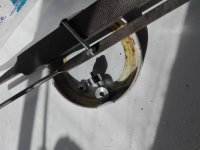 IMG_20220729_115804 - 03.jpg389.7 KB · Views: 79
 -
 IMG_20220729_115647 -04.jpg242 KB · Views: 74
 -
 IMG_20220729_131153 - 05.jpg223.7 KB · Views: 90
 -
 IMG_20220729_123502 -06.jpg289.6 KB · Views: 71
 -
 IMG_20220729_131808 - 07.jpg331.4 KB · Views: 83
LNR2A473MSE Capacitor Upgrade for Hafler 500 (No Longer Stocked)
- By ampexperts
- Parts
- 11 Replies
I've been using the LNR2A473MSE 47kuF 100V 63mm dia electrolytic as upgrade to the original 20kuF caps until recently.
I have another DH500 to upgrade this week, but all three suppliers show this as now being non stock item with min order of 25 pieces.
Does anyone know a source where this part is in stock?
I have another DH500 to upgrade this week, but all three suppliers show this as now being non stock item with min order of 25 pieces.
Does anyone know a source where this part is in stock?
Hypex SMPS400 minimum load for testing?
- By danmc91
- Power Supplies
- 2 Replies
I'm wondering if anyone knows the minimum loading that a Hypex SMPS400 may need on both the +/- main outputs as well as the +/- aux outputs for doing some basic go/no-go functional checks. I didn't see it on the Hypex data sheet but I could have just read right past it. The context for my question is the local high school has a commercially sold powered loudspeaker that the music department uses. It is based on the SMPS400 for the power supply, a custom pre-amp board and then 3 hypex amplifier modules (1 for the tweeter, 2 in bridge config for the bass/mid). There is a logo that is supposed to light up on the front of the unit but instead it flashes with a quick flash ever few seconds and there is no audio. I'd like to break the problem in half and decide if it is or is not the power supply which is what lead to my question about minimum load. Or can this unit handle running with no load? When the unit is fully connected (i.e. power supply, pre-amp, amp boards all connected normally), the supply main outputs are definitely not right (+ very low, - even closer to ground).
Regarding lab capability, I have access to various DMM, decent soldering equipment that is sufficient for the SMT stuff on the hypex boards, scope, microscope, and the usual sort of electronics bench hand tools. Regarding my experience, I'm an IC designer by trade but mostly not related to power electronics. That said, I've serviced tube amps as a hobby and in a previous life designed an offline flyback converter so I'm not totally without experience keeping my fingers and tools away from mains. For anything beyond a really light load I'll have to obtain something that can handle a bit more power.
FWIW, last year I fixed the other one of these units that the school has but in that case it was a linear regulator on the pre-amp board made out of discretes. That was a bit easier to track down even if the manufacturer did put a lot of goop on the components.
Anyone have a decent schematic for these supplies?
Thanks so much in advance.
-Dan
For Sale 5 Amperex Bugle Boy 6DJ8 ECC88 Tubes
- By LectroMoto
- Swap Meet
- 2 Replies
SOLD
These beauties test practically NOS on calibrated lo mile TV-2 tester as follows:
delta 7E2 90,95
delta 5L1 100,105
delta 7D2 102, 110
delta 7D2 93,93
delta 5L1 93,95
$75/all
These beauties test practically NOS on calibrated lo mile TV-2 tester as follows:
delta 7E2 90,95
delta 5L1 100,105
delta 7D2 102, 110
delta 7D2 93,93
delta 5L1 93,95
$75/all
Attachments

Hight quality songs
Hey ya,
Just wondering where is the best place to get music these days? I try to get music on cd for the sound quality as it beats downloading mp3s :O
Is there any website out there where I can purchase and download individual songs from that are at least cd quality? wav preferably?
Cheers
Just wondering where is the best place to get music these days? I try to get music on cd for the sound quality as it beats downloading mp3s :O
Is there any website out there where I can purchase and download individual songs from that are at least cd quality? wav preferably?
Cheers
6C33C-B on 8W
- By Tyimo
- Tubes / Valves
- 21 Replies
Hi!
Usually everyone wants to get the most out of this tube, e.g. 16W.
But what would be the ideal operating parameters for just a 8W version?
Greets:
Tyimo
Usually everyone wants to get the most out of this tube, e.g. 16W.
But what would be the ideal operating parameters for just a 8W version?
Greets:
Tyimo
Historic Harmonica Amplifier
- By gingertube
- Instruments and Amps
- 13 Replies
For your possible interest.
I have this amp on my bench for repair. The lady who brought it to me says it was her grandpa's Harmonica Amp and would like restored. Did a circuit trace. Very interesting tone control, treble boost/cut by feedback around the output tube. I looked up the tone control in RDH to find that the entire design is a 1942 W.N. Williamson design, Yep same Williamson who did the famous (well certainly the most copied) HiFi Amp design. Could have saved the circuit trace effort if I had know that up front.
6J7 triode mode to 6J7 pentode mode to 6V6 with an 80 rectifier. Lamp in standby switch line as a HT fuse.
Cheers,
Ian
Attachments

DC coupled condenser / fetless electret mic amp circuit
- By sirus20x6
- Analogue Source
- 46 Replies
A while ago I saw this post by DIY perks.
video here Login to view embedded media and resources here https://diyperks.com/project_31_high-quality-usb-c-microphone/
I was fairly intrigued so I bought the mic capsules. well they've been sitting on my shelf for a while and I was going to build the rest of it, but looking at his amp circuit i'm not really happy with what I see. it's ac coupled in 3 places. I also see that it doesn't have any negative feedback.

Then I did a bit of digging and found the "alice" electret amp circuit
https://www.instructables.com/OPA-Based-Alice-Microphones-a-Cardioid-and-a-Figur/

Now from a bit of digging I've heard this one is supposed to sound a bit better, but I see it's still AC coupled on the outputs, and it's for XLR while I want to use my sound blaster's 3.5mm microphone input. for power I'll probably use usb, and if I need to boost levels / get negative voltages I can use the NMA0515Sc from the first schematic. I would probably add some LC filters after the power regulator though.
Now onto my questions. Does anyone have a better circuit, maybe something dc coupled that would work for this situation. I'm also really unclear about what voltage levels the microphone input on my soundcard uses and I'm afraid to blow it out.
Also would bootstrapping the opamp be applicable at all?
Thanks
video here Login to view embedded media and resources here https://diyperks.com/project_31_high-quality-usb-c-microphone/
I was fairly intrigued so I bought the mic capsules. well they've been sitting on my shelf for a while and I was going to build the rest of it, but looking at his amp circuit i'm not really happy with what I see. it's ac coupled in 3 places. I also see that it doesn't have any negative feedback.
Then I did a bit of digging and found the "alice" electret amp circuit
https://www.instructables.com/OPA-Based-Alice-Microphones-a-Cardioid-and-a-Figur/
Now from a bit of digging I've heard this one is supposed to sound a bit better, but I see it's still AC coupled on the outputs, and it's for XLR while I want to use my sound blaster's 3.5mm microphone input. for power I'll probably use usb, and if I need to boost levels / get negative voltages I can use the NMA0515Sc from the first schematic. I would probably add some LC filters after the power regulator though.
Now onto my questions. Does anyone have a better circuit, maybe something dc coupled that would work for this situation. I'm also really unclear about what voltage levels the microphone input on my soundcard uses and I'm afraid to blow it out.
Also would bootstrapping the opamp be applicable at all?
Thanks
WTB TI / SAGAMI parts
hi
looking for some parts (probably like everyone else right now).
i'd like to finish STARKRIMSON amps and my needs are as per below list:
TI SN74LVC2G17DCKR 6pcs (minimum)
TPS7A4700RGWR 5pcs (minimum)
TPS7A3301RGWR 3pcs (minimum)
7G31A-100M 5pcs
7G23B-100M 10pcs
i was holding back with my order for to long and now sending rfq's everywhere i can 🙂
mouser shows availability dates close to nov.2022...
thanks!
Choke input(LC) and Lundalh Double Coil improved CMR
- By alecm
- Power Supplies
- 14 Replies
hi all,
here http://www.emissionlabs.com/Article...2-Circuit-Topology-for-Tube-Power-Supply.html

you can find the following statement :

" Circuit 5: This is how to connect a double coil Choke, such as the Lundahl LL1673 or similar products. Beware the polarity of the connections. (the dots in the circuit diagram here). The importance of this circuit is very high. We have complete inductive separation of the transformer from the amplifier. Definitely, the transformer capacitance from primary to secondary can not inject an AC hum current into the amplifier any more.
Design Quality of Circuit 5: Five Stars ***** "
in another word, this is the best possible connection with Lundahl chokes according to datasheet.
The question:
can I use this Circuit 5 connection not in CLC (capacitor input) mode but in LC (choke) mode?
as shown in the diagram below

here http://www.emissionlabs.com/Article...2-Circuit-Topology-for-Tube-Power-Supply.html
you can find the following statement :
" Circuit 5: This is how to connect a double coil Choke, such as the Lundahl LL1673 or similar products. Beware the polarity of the connections. (the dots in the circuit diagram here). The importance of this circuit is very high. We have complete inductive separation of the transformer from the amplifier. Definitely, the transformer capacitance from primary to secondary can not inject an AC hum current into the amplifier any more.
Design Quality of Circuit 5: Five Stars ***** "
in another word, this is the best possible connection with Lundahl chokes according to datasheet.
The question:
can I use this Circuit 5 connection not in CLC (capacitor input) mode but in LC (choke) mode?
as shown in the diagram below
Need help left ch. dc voltage on Sony TA-F444ESX
- By Itsme
- Solid State
- 27 Replies
Hello, Trying to repair the left channel on this Sony ES amp and not having much luck. Suppose to be getting 45 vdc +- on the left side but only getting around 32vdc +-, also getting around 5 vdc on the speaker +-outputs of that channel which isn't good and causing speaker to pop. Any help on this would be greatly appreciated.
Thanks
Thanks
Selectronic R core transformer for sale
50VA R core transformer with 2x0-18V secondary windings.
Asking £ 35 with UK delivery.


Asking £ 35 with UK delivery.
Canterbury Windings 400VA transformer for sale.
400VA Canterbury Windings Toroidal transformer with 2x0-22V secondary windings; interwinding screen and Goss band.
Asking £75 delivered UK only.


Asking £75 delivered UK only.
Opinion on the Behringer KM1700 Class-H amp
- By HumbleDeer
- PA Systems
- 44 Replies
Hey everybody!
Since I just ordered a Behringer iNuke 3000DSP for my subwoofer, I thought I'd look at my options for an amplifier for my fronts. I stumbled across the KM1700 because I know that it's basically like Class A/B but with a variable and dynamic voltage rail. Correct me if I'm wrong!
They're slightly (and that's a mild expression) overpowered at 2x500w into 8Ohms. My speakers are barely 90 Watts RMS (if they're set as fullrange. They can take slightly more when not in fullrange, I suppose. Or less? Less movement is less cooling hmmmmm.)
Since I'm not very good with the specification-sheet reading, what would your opinion be? I can't actually find a specsheet. 🙁
Any input is greatly appreciated.
Cheers,
Anna
https://www.amazon.com/Behringer-KM1700-BEHRINGER/dp/B01MAY7S7W
Behringer KM1700
limiter is switchable
front-to-back ventilation
frequency response: 20 Hz - 20 kHz (@-10 dB), 10 Hz - 80 kHz (@-3 dB)
THD: <0.03%
signal-to-noise: >100 dB
sensitivity: 0.77 V/26 dB/1.4 V (switchable)
dimensions: 482 x 375 x 88 mm (w*d*h)
weight: 12.5 kg
limiter is switchable
front-to-back ventilation
frequency response: 20 Hz - 20 kHz (@-10 dB), 10 Hz - 80 kHz (@-3 dB)
THD: <0.03%
signal-to-noise: >100 dB
sensitivity: 0.77 V/26 dB/1.4 V (switchable)
dimensions: 482 x 375 x 88 mm (w*d*h)
weight: 12.5 kg
Behringer KM750
- By carlos515
- PA Systems
- 20 Replies
Has anyone listened to the Behringer KM750 or know if it is ok for sub duty ? It is cheaper than the INUKE NU1000 but i don't know if the KM750 is quiet.
Downmixed to mono- freq imbalance?
- By SonocusEric
- Room Acoustics & Mods
- 2 Replies
I just got done building one channel of my monoblock and have been listening to both of my speakers fed from that with mono mixes. And i find that native mono mixes (from youtube) sounds excellent.
But some music downmixed to mono (either digitaly or with a switch) sounds horrible. The frequency balance is way off. So much so that it makes the amp sound as tho its broken.
Why is there such a discrepency and whats the science of it?
Thanks and regards
But some music downmixed to mono (either digitaly or with a switch) sounds horrible. The frequency balance is way off. So much so that it makes the amp sound as tho its broken.
Why is there such a discrepency and whats the science of it?
Thanks and regards
8 pin solid state rectifier RT 515 in Tubelab simple SE
- Tubes / Valves
- 7 Replies
Er der nogen som har erfaring med at erstatte ensretterrøret 5AR4 med en 8 pin solid state rectifier RT 515i en Tubelab simple SE power forstærker med El 34 monteret. Jeg har rørt 5AR4 monteret i 8 pin octal sokkel for tiden, men ønsker at prøve med solid state rectifier i 8 pin octal sokkel hvor rør normalt sidder. Jeg har ikke loddet dioder i printet og har kun 8 pin octal løsningen tilrådighed.

Third harmonic generator
- By dreamth
- Analogue Source
- 43 Replies
Can someone tell me a good way to obtain h3 and only h3?
Load more
Projects by fanatics, for fanatics
Get answers and advice for everyone wanting to learn the art of audio.
Join the Community
507,348
Members
7,866,433
Messages