Philips CDM3 Repair?

Hi, I was wondering if anyone knew of any detailed troubleshooting tips on the Philips CDM3 CD unit..or is it available in a service manual? I've got one with some intermittant problems, mostly on the side of not working at all...but sometimes it surprises me and works for a few minutes.

Just curious what normally goes bad on these or what I should perhaps be looking at, since I saw some previous posts about them being 'repairable'...

Any help is appreciated! Thanks!

Pete

Synthesis Magnum, commercial tube-chipamp hybrid...

I'm sitting here reading the latest Highfidelity (nordic Hifi-magazine) and they have tested the Synthesis Magnum 100 with great results.

It's a tube-buffered LM3886-based integrated amplifier using apparently 2 LM3886 in parallel/channel, each buffered with a ECC88/6DJ8-tube.

Some comments by the author of the article:

Magnum 100 showed it's self directly to be a very musical amplifier with a rich and warm mid-register.

The bas is rapid and rhythmic...

Above all the orchestral depiction sounded homogeneous and realistic...

Contrabass and cello felt solid and present...

Realistic representation of the piano sound is always difficult, even this did Magnum 100 with bravura...

The continued listening was done with regular CDs and confirmed the picture of the Magnum 100 as a very balanced and musical amplifier with a rich, warm midrange, an unstrained treble reproduction and a solid, well-detailed bas.


And on and on...

Overall they are very happy about the amplifier and I think its great fun to see a Hifi-paper test a chipamp-based amplifier without once mention anything negative (or for that positive) about the fact that it's build with chip-amps.

Have anyone here listen to the Synthesis Magnum 100 (or the 50, a smaller version with only one LM3886/channel I guess) and if so, how was it?

Attachments

  • 1_synthesisverst_rker-innen3.jpg
    1_synthesisverst_rker-innen3.jpg
    20.4 KB · Views: 1,001

DIY top to match MTH30 sub for small venues!

Hi,

I built an MTH-30 sub for our little ska/ reggae band and we are delighted with how well it works. Loaded with precision devices 12 running off crown amp. Kick sounds great.

I have 2 HK tops (old!) called "HK Compact." Replaced (! piezo) tweeters with APT150 and fitted 12 inch fane 250TC drivers to replace the fitted eminence 12LTA. Sounded much better. Also fitted new crossovers- tried a 2.5 and also 5 KHZ crossover. Not sure if they were a good idea...

Honestly - a stupid question - we like the tops as they are small, and that is very important in the small venues we play but they are a tiny bit harsh, ? at 5 KHz? maybe running the crossover too high, I think we can get a better sound. Not sure if the triple cone speaker should be allowed to run all the way as high as it can go and just have a HP on the tweeter instead?

I'm thinking of either replacing the tweeters/crossover - space is limited in the cab so would like a tweeter that could run a bit lower and also fit the APT150's plastic horn... Or maybe replace the speakers entirely with maybe something like a SLA Pro - some sort of column design or maybe Omintop 8 (with compression drivers not piezos!) - I'm very concerned at having ports on the side of the cab though as seems like a recipe for feedback??We would need a cab to do down to about 120Hz to meet the MTH-30 I think?

Probably stupid questions but if it was you and you had to build as narrow a cab as possible to match an MTH-30 sub to take full band (kick, keys, vox, bass) what would you do? We need horizontal and definitely NOT vertical dispersion where we play - low ceiling pubs in UK! Should I be looking at or 10's , 12's or maybe a column speaker/horn speaker of some sort. Not really up for a commercial powered cab as I like making speakers and after MTH-30 feel we can get good sound from DIY cab. We have another 1400w amp available. Any advice please? Great forum by the way!

LXmini measurements Klippel NFS

https://www.erinsaudiocorner.com/loudspeakers/linkwitz_lx_mini/


No set of measurements completely describe how a speaker sounds - it’s a visual translation of an auditory event- but Erin does it better than anyone else who is publishing measurements.

exhibit A:

1659514227766.png


@bikinpunk Thank you Erin, for listening work and descriptive comments before your measurements. Your methodology, experience and interpretation is advancing our understanding.

For dipoles, I must say the CTA2034A isn’t all that helpful- I went straight to the Youtube review to hear what you had to say about this speaker.

Attachments

  • 1659514574052.png
    1659514574052.png
    96.3 KB · Views: 190

Which Windows for the bench?

Hi folks,

20 year Mac user here so a little short on PC knowledge. I've had a 2011 Mac Mini (High Sierra) boot camped with Win 7 32 for probably 6 years. It's been solid but the drive is dying and my kids are claiming the Mac Mini so I need to start over.

I'll do a Bootcamped Mac again, likely used with a clean install of Catalina. What Windows version should I get?

My use case is pretty narrow - Prism dScope, maybe an Audio Precision in the mid term (likely older), simulation software (LTspice etc), Kicad, some speaker simulation stuff. All day to day Audio work is done on my Macs.

Should I buy Win 10? If so which version would you suggest? Or just go with Win 7 32 that I already own?

Thanks!
Ruairi

Windows 10 audio output quality

Windows 10 generates a 13dB increase in noise & distortion when going from Windows output level 99 to 100. I am posting Audio Precision APx555B analyses to illustrate.

This anomaly was verified in two ways: 1) USB to I2S to APx555B DSIO digital input, 2) USB to ASIO to Yamaha A-S801 headphone out to unbalanced APx555B analog input. The latter is illustrated.

THD+N (ratio) goes from -94dB @Windows 99 level out to -81dB @Windows 100 level out.

This bug is likely to be encountered, even by Audio professionals, because it is well known that audio quality is optimized by generating maximal digital levels out of a PC; i.e, controlling volume on a downstream analog audio amplifier.

Attachments

  • aa.jpg
    aa.jpg
    322.9 KB · Views: 813
  • ab.jpg
    ab.jpg
    376.2 KB · Views: 820
  • ac.jpg
    ac.jpg
    486.1 KB · Views: 862

Oscilloscope Recommendations or Referrals?

Hello,

As the title suggests, I am looking for any general or specific recommendations or referrals. While I do have some clue (and am a trained EE), I am certain some people here just have much more knowledge about what's available and what's best. I am open to new or used, bench or portable, etc.

I am sort of a repair hobbyist, I work on particular older car audio equipment, sometimes with the help of Mr. Babin or other distinguished contributors. This is for personal use or small jobs for friends or acquaintances.

I don't want to break the bank, but I do have a reasonable budget and may pay more if it's right.

Thank you for any suggestions or feedback!

TapeHead Tube Preamp Schematic Question

Hi Guys,

I've recently build a reel to reel playback tape head tube preamp. I have followed the Tandberg 64x tube preamp schematic however something is not adding up and maybe someone can clarify if this is normal behavior. I have checked the build and everything is as per schematic.

Tandberg doc specifies that the cathode follower output is 1.5V. Mine is 12.2mV which is a huge difference. I have traced the signal and the values can be seen in the attached schematics. Also, the plate and cathode voltages are correct in my build as specified in the Tandberg doc. I also removed the entire EQ part and the results are the same.

Did I do something wrong or the values measured look right to you?

Thanks

Attachments

  • Preamp&EQ.jpg
    Preamp&EQ.jpg
    119.6 KB · Views: 1,577
  • CathodeFollower.jpg
    CathodeFollower.jpg
    60.7 KB · Views: 683

FS: Dale NH-100 4-ohm, 100W, non-inductive resistors

I have several used Dale NH-100 4-ohm, 100W, non-inductive resistors. Theye are the aluminum housed, chassis mount ones that are great for dummy loads. I have at least a couple dozen. These were mounted on heatsinks, which I might have access to (in storage) in the coming week.

These will ship from Encinitas, California. Asking $15 each, plus shipping. Local pick-up is also fine.

Click on images for proper resolution.
attachment.php


attachment.php


attachment.php


Cheers,
-Casey

Attachments

  • Dale-NH-100_001.JPG
    Dale-NH-100_001.JPG
    778.1 KB · Views: 717
  • Dale-NH-100_002.JPG
    Dale-NH-100_002.JPG
    838.2 KB · Views: 704
  • Dale-NH-100_003.jpg
    Dale-NH-100_003.jpg
    271.6 KB · Views: 562

New use for old DIY stuff

Like a lot of you I have a lot of old projects laying around unused so I decided to make a deck bluetooth boom box out of some decent but unused old stuff. Inspiration came from an old picnic set that I ran across in a thrift shop. I stuffed an old MRefC chip amp, a Subbu DAC, a Kookabarra preamp, and an ebay bluetooth gismo into the case and added power. Easy to transport and sounds great. Using Mark Audio full range speakers.

Attachments

  • in use.jpg
    in use.jpg
    271.9 KB · Views: 139
  • Inside1.jpg
    Inside1.jpg
    539.5 KB · Views: 155
  • Old picnic set1.jpg
    Old picnic set1.jpg
    511.7 KB · Views: 145
  • picnic basket1.jpg
    picnic basket1.jpg
    699.1 KB · Views: 136
  • stuffing1.jpg
    stuffing1.jpg
    453.8 KB · Views: 155

Turntable CEC repair antiskating

This turntable has been used by people who were careless, drugged, or drunk. 😢
It has the AS system pin broken in a very difficult place to remove and replace with a new one. Luckily they didn't throw the balance weight.
It is very difficult to work with the arm installed, would it be necessary to make a small well-centered hole and get an extractor...so small? Or drill everything and make a new supermeasure thread.
Or extract the arm from the chassis and take it to a microturning specialist... All of that would take a lot of effort and money.
So you can see my solution. In a few hours it was ready, the hardest part was getting a new bolt of the exact size. So I had to file down a threaded screw until it worked smoothly, with just the right amount of clearance.
The result is satisfactory, the AS works perfectly.
Now the arm lock on his seat needs to be repaired, but that will take time, I'll have to make the piece out of copper plate. I have done this work before on a capsule holder spindle and it turned out very well. For now, I leave you the photo show.
The secret was to make a small cavity above the new bolt to match the tiny bolt rest protruding from the main body.
That put him in his correct position. And the cable gland secured it in place.

Attachments

  • IMG_20220729_122334 -  01.jpg
    IMG_20220729_122334 - 01.jpg
    342.6 KB · Views: 85
  • IMG_20220729_115022 - 02.jpg
    IMG_20220729_115022 - 02.jpg
    416.6 KB · Views: 78
  • IMG_20220729_115804 - 03.jpg
    IMG_20220729_115804 - 03.jpg
    389.7 KB · Views: 79
  • IMG_20220729_115647 -04.jpg
    IMG_20220729_115647 -04.jpg
    242 KB · Views: 74
  • IMG_20220729_131153 - 05.jpg
    IMG_20220729_131153 - 05.jpg
    223.7 KB · Views: 90
  • IMG_20220729_123502 -06.jpg
    IMG_20220729_123502 -06.jpg
    289.6 KB · Views: 72
  • IMG_20220729_131808 - 07.jpg
    IMG_20220729_131808 - 07.jpg
    331.4 KB · Views: 83

Hypex SMPS400 minimum load for testing?

I'm wondering if anyone knows the minimum loading that a Hypex SMPS400 may need on both the +/- main outputs as well as the +/- aux outputs for doing some basic go/no-go functional checks. I didn't see it on the Hypex data sheet but I could have just read right past it. The context for my question is the local high school has a commercially sold powered loudspeaker that the music department uses. It is based on the SMPS400 for the power supply, a custom pre-amp board and then 3 hypex amplifier modules (1 for the tweeter, 2 in bridge config for the bass/mid). There is a logo that is supposed to light up on the front of the unit but instead it flashes with a quick flash ever few seconds and there is no audio. I'd like to break the problem in half and decide if it is or is not the power supply which is what lead to my question about minimum load. Or can this unit handle running with no load? When the unit is fully connected (i.e. power supply, pre-amp, amp boards all connected normally), the supply main outputs are definitely not right (+ very low, - even closer to ground).

Regarding lab capability, I have access to various DMM, decent soldering equipment that is sufficient for the SMT stuff on the hypex boards, scope, microscope, and the usual sort of electronics bench hand tools. Regarding my experience, I'm an IC designer by trade but mostly not related to power electronics. That said, I've serviced tube amps as a hobby and in a previous life designed an offline flyback converter so I'm not totally without experience keeping my fingers and tools away from mains. For anything beyond a really light load I'll have to obtain something that can handle a bit more power.

FWIW, last year I fixed the other one of these units that the school has but in that case it was a linear regulator on the pre-amp board made out of discretes. That was a bit easier to track down even if the manufacturer did put a lot of goop on the components.

Anyone have a decent schematic for these supplies?

Thanks so much in advance.

-Dan

Historic Harmonica Amplifier

For your possible interest.

I have this amp on my bench for repair. The lady who brought it to me says it was her grandpa's Harmonica Amp and would like restored. Did a circuit trace. Very interesting tone control, treble boost/cut by feedback around the output tube. I looked up the tone control in RDH to find that the entire design is a 1942 W.N. Williamson design, Yep same Williamson who did the famous (well certainly the most copied) HiFi Amp design. Could have saved the circuit trace effort if I had know that up front.
6J7 triode mode to 6J7 pentode mode to 6V6 with an 80 rectifier. Lamp in standby switch line as a HT fuse.

Cheers,
Ian

Attachments

  • Harmonica Amp.jpg
    Harmonica Amp.jpg
    42.9 KB · Views: 1,007

DC coupled condenser / fetless electret mic amp circuit

A while ago I saw this post by DIY perks.
video here Login to view embedded media and resources here https://diyperks.com/project_31_high-quality-usb-c-microphone/

I was fairly intrigued so I bought the mic capsules. well they've been sitting on my shelf for a while and I was going to build the rest of it, but looking at his amp circuit i'm not really happy with what I see. it's ac coupled in 3 places. I also see that it doesn't have any negative feedback.
V1 schematic.jpg


Then I did a bit of digging and found the "alice" electret amp circuit

https://www.instructables.com/OPA-Based-Alice-Microphones-a-Cardioid-and-a-Figur/

Screenshot_2022-07-01_09-32-41.png


Now from a bit of digging I've heard this one is supposed to sound a bit better, but I see it's still AC coupled on the outputs, and it's for XLR while I want to use my sound blaster's 3.5mm microphone input. for power I'll probably use usb, and if I need to boost levels / get negative voltages I can use the NMA0515Sc from the first schematic. I would probably add some LC filters after the power regulator though.

Now onto my questions. Does anyone have a better circuit, maybe something dc coupled that would work for this situation. I'm also really unclear about what voltage levels the microphone input on my soundcard uses and I'm afraid to blow it out.

Also would bootstrapping the opamp be applicable at all?

Thanks

WTB TI / SAGAMI parts

hi

looking for some parts (probably like everyone else right now).
i'd like to finish STARKRIMSON amps and my needs are as per below list:
TI SN74LVC2G17DCKR 6pcs (minimum)
TPS7A4700RGWR 5pcs (minimum)
TPS7A3301RGWR 3pcs (minimum)
7G31A-100M 5pcs
7G23B-100M 10pcs

i was holding back with my order for to long and now sending rfq's everywhere i can 🙂
mouser shows availability dates close to nov.2022...

thanks!

Choke input(LC) and Lundalh Double Coil improved CMR

hi all,

here http://www.emissionlabs.com/Article...2-Circuit-Topology-for-Tube-Power-Supply.html
vt-logo.svg


you can find the following statement :

1659111223916.png


" Circuit 5: This is how to connect a double coil Choke, such as the Lundahl LL1673 or similar products. Beware the polarity of the connections. (the dots in the circuit diagram here). The importance of this circuit is very high. We have complete inductive separation of the transformer from the amplifier. Definitely, the transformer capacitance from primary to secondary can not inject an AC hum current into the amplifier any more.
Design Quality of Circuit 5: Five Stars ***** "

in another word, this is the best possible connection with Lundahl chokes according to datasheet.

The question:

can I use this Circuit 5 connection not in CLC (capacitor input) mode but in LC (choke) mode?

as shown in the diagram below

1659111989224.png

Opinion on the Behringer KM1700 Class-H amp

Hey everybody!

Since I just ordered a Behringer iNuke 3000DSP for my subwoofer, I thought I'd look at my options for an amplifier for my fronts. I stumbled across the KM1700 because I know that it's basically like Class A/B but with a variable and dynamic voltage rail. Correct me if I'm wrong!

They're slightly (and that's a mild expression) overpowered at 2x500w into 8Ohms. My speakers are barely 90 Watts RMS (if they're set as fullrange. They can take slightly more when not in fullrange, I suppose. Or less? Less movement is less cooling hmmmmm.)

Since I'm not very good with the specification-sheet reading, what would your opinion be? I can't actually find a specsheet. 🙁

Any input is greatly appreciated.

Cheers,
Anna

https://www.amazon.com/Behringer-KM1700-BEHRINGER/dp/B01MAY7S7W

Behringer KM1700
limiter is switchable
front-to-back ventilation
frequency response: 20 Hz - 20 kHz (@-10 dB), 10 Hz - 80 kHz (@-3 dB)
THD: <0.03%
signal-to-noise: >100 dB
sensitivity: 0.77 V/26 dB/1.4 V (switchable)
dimensions: 482 x 375 x 88 mm (w*d*h)
weight: 12.5 kg

Downmixed to mono- freq imbalance?

I just got done building one channel of my monoblock and have been listening to both of my speakers fed from that with mono mixes. And i find that native mono mixes (from youtube) sounds excellent.

But some music downmixed to mono (either digitaly or with a switch) sounds horrible. The frequency balance is way off. So much so that it makes the amp sound as tho its broken.

Why is there such a discrepency and whats the science of it?

Thanks and regards

8 pin solid state rectifier RT 515 in Tubelab simple SE

Er der nogen som har erfaring med at erstatte ensretterrøret 5AR4 med en 8 pin solid state rectifier RT 515i en Tubelab simple SE power forstærker med El 34 monteret. Jeg har rørt 5AR4 monteret i 8 pin octal sokkel for tiden, men ønsker at prøve med solid state rectifier i 8 pin octal sokkel hvor rør normalt sidder. Jeg har ikke loddet dioder i printet og har kun 8 pin octal løsningen tilrådighed.
16590414488993818983236462799082.jpg

Smt Schottky diode recommendation (preamp)

Hi im trying to reformat my preamp to smt format through jlcpcb. Its a mono mono double bridge config, each channel 18 0 18 0 ac input and up to 500ma bias output at +-15vdc rails.

Until now ive been using uf4004 diodes and now since looking into smt schottkys im overwhelmed by the number of choices thats at jlcpcb.

Anybody have a good recommendation on them? What are some user favorites? Thanks

which EI Transformer to use?

Hello,

My old CD player has small EI transformer which is starting to hum badly so try to replace with a quality one.

When I measure the voltage of primary and secondary windings of existing transformer, I got below readings.

Primary: 52.8 Ohm, 245V
Secondary: 5 ohm, 30.3v

Dimension is 55mm L x 20mm D x 45mm H.

I am aware of that I need to get 230v primary voltage rating transformer but not sure,

(a) if I need to get 28V or 30V secondary voltage rating since actual AC feeding to it from main is 240~250v.
(b) what power rating transformer should be given the dimension of the transformer mentioned above.
(c) And, which company's EI transformers are reliable? I am thinking to get either Triad or Hammond from Mouser. Are they good enough?

Thank you so much for guidance and help on this.

B1 Problem

I've recently finished my third and fourth B1 boards (bought from the official source, with the JFETs). The two boards were built identically (for balanced operation, eventually), with extra-high quality parts (e.g., Z-Foil resistors in the signal path).
One of them is working perfectly, but the other is giving me problems. I'm guessing it is because, when first testing it, I hooked up the power supply backwards. Presumably, that could have damaged (or worse) the filter caps. Before I swap those out, though, I thought I'd ask here, and see if anyone had other ideas.
The symptom is bad distortion in both channels, and what seems like low volume, as well. I used to hear something similar when using batteries with my other B1, when they would start to die. But voltage measures OK at e.g. the gate of Q100.
I'll attach a photo of the board in my test enclosure, though I don't know if that will be much help.

20220802_190900.jpg

Kenwood KA-8011

Hello guys,

I would like to ask something about my ka-8011 which is same as kenwood ka-801. I don't have the amplifier for long time and it is working lets say normally.

It was surprise for me when I opened bottom cover and saw this.. Path to Q1 collector burnt. What can cause this and how it is possible that it can still working with burnt path ?

Thanks a lot

Attachments

  • IMG_20220618_225158.jpg
    IMG_20220618_225158.jpg
    675.6 KB · Views: 240
  • Untitled1.png
    Untitled1.png
    585.8 KB · Views: 245
  • Untitled3.png
    Untitled3.png
    387.5 KB · Views: 288

Building a crossover with foil inductor

Dear all,

I've ventured into building a crossover for a two-way speaker system. I acquired capacitors and inductors from Mundorf, but now I'm scratching my head with the task of soldering all together. The inductors are made out of something that look like copper foil and I have never soldered something like this. Is there are right way of doing it? Do I need to somehow fix the foil before soldering? Or it should hang free off the inductor?

Touring HiFi2000

Folks:

My wife and I had the opportunity to tour the HiFi2000 factory in July, and it seemed appropriate to post a brief write-up about the experience. Gianluca (the principal contact for HiFi2000 and a regular contributor here at diyAudio) and I were trading PMs a few months ago when I mentioned an impending vacation in Italy that included a few days in Bologna. His response: “why don’t you come for a tour?” I immediately agreed.

It turns out HiFi2000 is a tiny, family-owned business that was started in 1977 by Gianluca’s parents. They’re ostensibly retired, though the day we visited they were hard at work helping to fill orders. Gianluca now runs the business, which is located close to Bologna’s airport in an industrial park and consists of a few offices, a design studio, two CNC systems in a workshop area (where panels and heat sinks are drilled, threaded and customized), a digital printing station, inventory storage and management systems and an order fulfillment area. I believe Gianluca said there was a staff of 7 or 8 people, including his parents and himself.

The operation struck us as incredibly efficient (though for all my wife and I know it may be the norm these days). There was a person in the front office, someone in the design studio and someone operating the CNC systems; everyone else was busy gathering parts and/or putting orders together. Gianluca was very proud of the fact that HiFi2000’s products are 100% Italian – for example, the aluminum for their panels is smeltered in Northern Italy and cut to size by a vendor in the Bologna area. Anodizing is outsourced to a nearby shop. Most of the other components are also locally sourced. Gianluca was passionate about customer satisfaction, HiFi2000’s efforts to accelerate deliveries to customers and supporting their market generally. It was rewarding listening to someone who is deeply invested in what he does.

Hanging out with Gianluca for an hour was a pleasure. I did a rough count and it seems I’ve purchased (or directed people I was helping with projects to purchase) about 19 chassis from HiFi2000 over the past 15 years or so (naturally, there are plenty more projects in the works). It was fun seeing how it all comes together. There are a lot of ways to spend your time in Bologna, and for me the tour was a far better experience then watching sausage being made.

Regards to all!

Attachments

  • tempImage54R587.gif
    tempImage54R587.gif
    1.9 MB · Views: 138
  • tempImagewU9nsu.gif
    tempImagewU9nsu.gif
    1.6 MB · Views: 144
  • tempImagelutyYX.gif
    tempImagelutyYX.gif
    1.4 MB · Views: 132
  • tempImagesiVsM0.gif
    tempImagesiVsM0.gif
    1.8 MB · Views: 159
  • tempImageXfE4xe.gif
    tempImageXfE4xe.gif
    1.6 MB · Views: 129
  • tempImageEpnPZu.gif
    tempImageEpnPZu.gif
    1.4 MB · Views: 126
  • tempImagedE7LNj.gif
    tempImagedE7LNj.gif
    1.6 MB · Views: 134
  • tempImageIRW8a8.gif
    tempImageIRW8a8.gif
    1.7 MB · Views: 133

Arcing rectifier -- seeking sage advice

Hey everyone!

This past week I purchased a used Yamamoto A-08s amplifier. This came after months of research and careful decision making. It's also my first foray into the tube world, after owning solid state gear for decades. As such, I'm sorry for any silly or irrelevant points I may bring up, as they will be extensions of my very basic understanding of valves and their circuits (I'm learning experientially).

Here's the situation. After a very careful unboxing and clean-up, I'm happy that the amp is visually in mint condition. I finally got to the point of powering it up last night, and immediately the rectifier tube (80) began to arc and flicker. I did a few hours of research, and it appears to me that it was not what people call 'tube flash', but rather arcing, or 'cathode stripping'. I let it go for about 3 seconds to see if it would stop, but then made the quick decision to power it back down... then immediately started researching.

From what I gathered, it seems that this is caused by the tube being 'overtaxed' from two factors -- first, on a cold startup, it is only able to operate at a fraction of it's 'warmed up' ability. Second, and compounding the issue, is that the tubes highest demand period is right at startup, when it need to charge a large 'empty' capacitor. Again, I'm sure this assessment is begging for corrections or clarifications.

In addition to any general advice people may have, I have a few specific questions:

1. What are the chances that this compromised or damaged any other component in the amp? From what I gather, some people just let the tube arc at startup and let it subside after it warms up, but I'm not so brave myself... so hopefully this means that it is 'safe' for everything else in the amp.

2. Could this issue have anything to do with the fact that I'm powering it through a Furman "IT-Ref 20i" isolation transformer? I know that each AC leg is split to carry 60v each in this design, as opposed to the 'regular' 120v + neutral... It just had me thinking, what if there is an incompatibility there somehow?

3. Could this be actually be a normal occurrence for a healthy tube that hasn't been powered on for some time? I don't know when it was last used / powered up... but if it's been years, perhaps time has some relevant effect. If this is the case, should I keep using the tube, or is it dead?

I turned to this community first because you guys seem like you really know your stuff -- thank you for any and all help!

Power supply filter / choke best practices for EMI? (DC)

I'm designing a 100W class D amplifier, with discrete components (IRF8707 and IRS2011 gate drivers), running at about 350kHz. There's a lot of energy moving on this thing, so I'd like a good starting point. (Assume good PCB design practices have been used.)

What's the best practice for filtering the DC power input?

1. Common-mode choke between the DC input and power amp? (Between the applied voltage/gnd and the internal applied voltage/gnd)
2. Series inductor or ferrites on input? (At 24V supply, this would be several amps but possibly)
3. Combined one of the above with copious capacitor bypass of course.

The line inputs are referenced to the "true ground" - PCB ground plane, circuit ground, shield, which could be slightly isolated by the CM choke if I used it.

I'm of course going to test all this, but I wanted to get a sense of a good starting point.

Foolproof Fixed BIAS Simulator with LTSpice for PP

Hi !

I made a foolproof fixed BIAS simulator with LTSpice for push-pull output stage (LTSpice is freeware). The idea of foolproof BIAS circuit was inspired by the Soloist amplifier designer. Even if BIAS potentiometer go south with total annihilation of the wiper, vacuum tube will not overheat and burn. Additionally, it allows to fit available components. For example, I have a box of 33K potentiometers which I would like to use for BIAS adjustment of PP KT88.
Entire archive enclosed, you will need to open *.asc file in LTSpice, edit values, types of tubes, etc., and run simulation. For output tubes other then KT88 - download, copy and include another *.lib file from within *.asc.

I changed resistors to lower values (compared to Soloist), as IMHO Soloist's grid leak final value is too high.

Self-explanatory screenshots attached. 2nd simulation is with broken wiper.

Enjoy !

Attachments

  • Screenshot at 2022-08-03 00-54-57.png
    Screenshot at 2022-08-03 00-54-57.png
    306 KB · Views: 172
  • Screenshot at 2022-08-03 00-55-48.png
    Screenshot at 2022-08-03 00-55-48.png
    174.4 KB · Views: 191
  • BIAS-Calc.zip
    BIAS-Calc.zip
    2.8 KB · Views: 98
  • Like
Reactions: gerrittube

ACA speaker binding post issues

I have 2 ACA kits the first one I completed 7 months ago and has no issues. The second kit I just completed and I am having problems getting a good connection to the speakers. I noticed the binding posts in this new kit are slightly different than the first kit. There is no brass/copper? shoulder sticking above the plastic, the plastic holding the contact point and the contact itself are flush so when you snug them down on a spade it hits the plastic and not the contact, unless you really fuss with it and crank it down. In the image below the first kit is on the right and the new kit is on the left. Is this a bad part? I don't see how it can work. All 4 posts in the new kit are like this.

--Doug

IMG_1358.jpeg

Help flattening the SPL spectrum of my room

Hello everyone,

I have been tackling some issues in the SPL curve of my room using a 2-step room correction (after proper acoustic treatment).

Would anyone be knowledgeable enough to explain me what's happening:

My strategy has been: using MSO to handle the lower part of the spectrum and then using REW EQ filters for the rest.
For the low end, I optimize with MSO until 300 Hz and I implement the result biquads in my miniDSP 2x4HD. It works great.
For the rest of the spectrum, I calculate the EQ in REW. I then put the filter impulse response into a convolution device to flatten the curve above 200 - 300 Hz. It works fine.

The audio goes first thru the convolution in my DAW then out to the miniDSP then to the speakers and sub.

Individually each technique does the job but when I do the whole thing I get a nasty dip from 200 Hz to 2 kHz...

This happens only on one speaker (the room being not perfectly symmetrical).

Would that be some sort of phase issue?

I can provide more info and graphs (but when I did on another forum no one dared to answer 🤔).

Many thanks.
Cheers,

ECC81/300B Push Pull Amp

I built this 2-stage 300B Push Pull amp.
It was pedestrian with garden variety 12AT7/ECC81,
but really sings with super ECC81 tubes like
GEC A2900 and ECC801S.
After several failures building PP amps, this is a keeper.😗

Inspiration came from John Tucker's parafeed 45, which uses
CCS loaded parallel 5965 (12AT7 variant) triodes as driver.

I am in the process of building a 5691 (super 6SL7 ??) drives 300B/45 PP version,
6SL7 has more mu.
Not sure if 5691 has as much super power as A2900 or ECC801S ?

Currently, it is using the secondary of LL1660S (an interstage transformer)
as the phase inverter (center-tapped choke).
It is lacking some lower ends due to the inductance (~20H).

Suggestions on the availability of higher inductance ( > 40H)
center-tapped chokes (or 1:1 inverted transformers),
and comments are welcomed.

Attachments

  • 300bpp_ECC81.jpg
    300bpp_ECC81.jpg
    74.6 KB · Views: 1,101

Recapped my Niles si-275 today

Im pretty new to hifi stuff. Within the last few weeks Ive put together my first system comprised of jbl stage a130s, ran by a niles si-275, fed by an aiyima t7 tube preamp. It sounds great. Ive never experienced music actually placing instruments or any of that magic until this system. Ive done a bit of tinkering as well. I replaced the op amps in the aiyima with a slightly cleaner lm4562 and gave it a meanwell power supply. Today I went ahead and replaced the power caps and 2 of the filter caps in my si-275, due to age and a bit of puffing. I can honestly say that none of this made any change to the way the system sounds, but its nice to know that maybe ive taken care of some potential for noise and reliability issues in the future.
Anyway, I just wanted to share in case there are any other new guys out there trying to get some ideas or motivation for their project

Attachments

  • IMG_20220314_104633977.jpg
    IMG_20220314_104633977.jpg
    413.1 KB · Views: 254

FIX FOR THUMP

You need to isolate the speaker(s) and control their connection to the amp.

Parts:
12VAC transformer, 24W or a 12VDC 2A wall adapter.
AliExpress 30A speaker protector circuit AIYMA 900W. I used their 30A mono device. $7.60
Install a toggle switch OR smart device Alexa or Kasa (By TP-Link) smart WI-FI plug HS103.
Connect between amp and speakers. Mount with hot glue gun.

Now control amp with Kasa app on phone or use toggle switch or use Alexa to power on or off speaker.

LME49810 based amplifier PCBs

I am interested in building a 4 channel amplifier (for biamping with active crossover) based on the lme49810 driver IC, of which i have a few. Some time ago there were a bunch of projects based on this IC with PCBs available to buy but being a discontinued part they all seem to have evaporated. The only remaining pcbs i can find are Chinese kits which are either silly 300w things, or more appropriately sized but suspiciously simple looking. They also come as a full kit (usually excluding the 49810) of parts i wouldn't trust which doesn't make it an attractive proposition

Does anyone know of any reputable projects based on this IC either still selling PCBs, or with pcb artwork available that could be sent off to one of the PCB houses to reproduce?

FS - Twisted Pear Buffalo III ES9018 SABRE32 DAC, power supplies, inputs etc.

Hello DIY audio... ers!

This is everything you will need to get an incredible sounding DAC up and running. A great winter project! 🙂

The IVY board is populated, everything else is untouched and new.

Buffalo III DAC, Trident Regulator set & volume control - assembled and tested by TPA. Retail $379.
IVY III linestage, Placid HD-BP power supply, LCDPS along with 9V and 15V transformers - Retail $210.
4 Channel S/PDIF 4 module $55.
Toslink optical input module $15.
LCDPS power supply $55.

Retail prices shown for reference. Add 33% for tax and duty to get an idea of original cost to Sweden so total was about 1000EUR after shipping and taxes/duties.

Looking for 550EUR for everything.

The DAC is mounted to the IVY, but not soldered.

Thanks for looking, and take care,
Peter
IMG_20211214_110724665.jpg
IMG_20211214_102909958.jpg

Does anyone have the patience to help me with a Linn Valhalla upgrade?

Hello, I know this subject has been done to death and I am reading through the old posts - and https://andydoz.blogspot.com/2019/09/the-comprehensive-linn-valhalla-repair.html

Let me tell you my situation. I purchased a perfectly working un modified valhalla.. i tested it, all good, but I knew it was a bit dated. It worked and I checked all the HV and low V. All good ( 300+v on caps ) motor span no probs. Caps looked old.

My plan was to replace things one at a time, starting with R1, testing at every stage to ensure it still worked.

I know this post will offend some people as I am looking for a hand for something thats been done a 1000 times

I first changed R1 to a inrush varistor - I made the mistake of not do ing this one thing and re checking, as was my plan. One thing replace, check next thing.

At the same time as R1 I also changed R2 & R3 with 7w 15k wire wounds as I thought "why not - easy "

Well after the 2 changes the valhalla no longer works. I get no 300+v DC on caps on C1, and basically a dead board.

I have traced the HV with my meeter the varister seems OK, fuse OK. I think I maybe burnt a copper track with the big resistors.

Can anyone give me a hand fixing this? I have a scope ( that I know how to use ) a mulimeter and I probably even have a isolation transformer somewhare .

My goal is to have a valhalla in an external box I can use between decks & do a real comparison butween a basic supply ( .2uf 90deg cap based phase shift ) and a DIY geddon so see if a moron like me could actually hear a difference.

If anyone is up for helping I would be greatful.

Thanks

Chris

(Informal) Chat with Dr. Earl Geddes of GedLee Audio

Last week I asked Earl - in a thread here - if he would be willing to come on my YouTube channel and talk about a few different topics ranging from nonlinear distortion to how reviewers can do better. He obliged. It was a great opportunity to talk to someone who I truly admire and respect. You’ll have to excuse me for occasionally “fan-girling”. 😉 😀

YouTube

* I'll try to add bookmarks to this when I get the time

Personally, the discussion was very beneficial for me as it gave me some ideas on areas I can improve my reviews. If you watch you’ll see we talk about compression and I mention that I perform what I would consider a “dynamic” test. He suggested doing long term compression and convinced me to add that back in to my arsenal. So I’ll be incorporating that in future reviews but in a different manner than I had done before.

I also was simply unaware that - due to masking - our ability to hear distortions of a loudspeaker are lessened as we increase output. This makes me think that it might be more beneficial to test HD components at lower SPL.... or potentially just not worry about it altogether. (I already provide 86dB and 96dB @ 1m HD components for loudspeaker/transducer tests)


I have to thank Earl again for joining me and helping me (us) understand the various aspects of nonlinear distortion and I appreciated his insight in to the other topics we touched on.

NAD C352 Integrated Amplifier 120v 60Hz to 240v 50Hz

Hello,

I moved to a country with 240v 50Hz so my NAD C352 originally built for 120v 60Hz need to be converted to be used without step down transformer.

I am wondering if it is possible to convert to 240v 50Hz by simply replacing suitable toroidal transformer. The transformer itself does not have any sticker indicating voltage rating but NAD logo on top only.

When I read service manual, the part number are two (one is C and the other is AH version, not sure what the differences are).

Can any one enlighten me if it can be done by replacing transformer or it is a lot more than that? (hope it is simple swap).

If it can be done, then which transformer do I need to get?

To save time, I attached service manual for reference too.

Thank you so much and any help would be hugely appreciated.

Attachments

Best budget capacitors for speaker crossover restoration

Hi Everyone,

I bought a pair of B&W DM2ii speakers, which look great to my eyes. Really nice condition in Teak & generally they sound pretty good, but the sound is a bit hollow on some music, and the treble could do with being a bit brighter, although the actual situation isn't too bad TBH. All drivers are working well, but I feel a recap or refresh of the crossovers is required after 43 years.

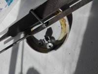
These speakers have 9 caps on each crossover, so 6 pye electrolytics for the LF & MF, and 3 film (metallised?) caps for the HF. As mentioned it would be good if a little bit more sparkle was restored to the tweeters.

I have been looking at various on-line shops in Europe & UK, and I must admit it's pretty confusing between the different makes & types, with some big price differences for polyproplyene caps depending on the make & model. Basically this is a pocket money hobby for me, and I don't want to spend too much on restoring them, so I am looking for the best sweet spot between cost & quality. This is my plan :

LF & MF :
Use good quality electrolytics. My considered options are ALCAP low loss, ALCAP 100V, or Mundorf E caps
The advantage of the ALCAP range is that they have the exact same capacitance capacitors as the original caps (ex 80uf, 30uf, 20uf etc) whereas all other makes including MKT types, tend to have a nearby equivalent but not the same capacitance (ex 82uf, 33uf, 22uf)
Can anyone advise what would be best, or any alternative ideas ?

HF :
The orignal capacitors are 3 square rectangular film type caps (5uf in series, 2.2uf & 0.47uf in parallel), in close proximity to other components, and maybe it would be a squeeze to use some large Polyproplyene caps.
My options here are Mundorf Mcap, Jantzen standard Z cap, SCR MKP or Solen MKP, or even WIMA MKP type film caps which would fit the board.
Again, can anyone advise what would be the best compromise ? I want to brighten up the tweeter a bit, but dont want to go overboard or regret it afterwards. I guess trying to be as close as possible to original sound is the target.

Many thanks

Sugden A88

Hi, I bought this very rare 110v A88 for spares to repair a broken 240v one. Because of it's voltage, it had not , I think, been used much. The nextel was all gloopy and it looked terrible. I converted it to 240 volts, according to helpful instructions from Sugden. Unused for many years, it worked beautifully first-time (after passing the light-bulb test)! A tribute to Sugden build quality! The sound is sublime- clearly Sugden, but also very fast, a bit like Naim! It's a slightly odd design, I think, with 2 transformers (in series?), and puts out 80w into 8 ohms and 150w into 4 ohms. Patrick Miller at Sugden told me that they had been specially made for export to Nigeria, but the buyer was fraudulent, so they were sold in the UK and US markets for a brief period instead. Sonically it is just excellent! I am working from an A44 schematic, which is similar, but with only one transformer. I have 2 amps to make one out of, one working nicely (though with a slightly quiet left channel) and one very battered and intermittent. I am not brilliant at electronics, but really want to restore one to perfection. I have 4 questions, firstly does anyone have any recommendations about capacitor make to preserve the sonic signature? Secondly, does anyone know where one could get small bits re-coated with nextel (or should I just go with paint or powder coating?), thirdly, how do you re-label the dials on the front after re-surfacing the coating? I could just try to re-case it all, but that seems wrong really! I have included some pictures! Thanks for any help or comments
Jo

Attachments

  • IMG_0001.jpg
    IMG_0001.jpg
    430.2 KB · Views: 1,158
  • IMG_0002.jpg
    IMG_0002.jpg
    483.8 KB · Views: 1,053
  • IMG_0007.jpg
    IMG_0007.jpg
    554.9 KB · Views: 1,083

Got an old broken receiver from the 60s, repaired it but the noise floor is still to high.

It is an AM-320 from palace audio, it only had a broken powersuply cap. So when I replaced it I was like: "Wow that was easy" but noo!

I mean, it does work now. But the noise floor is terrible (like 50% signal 50% noise)...
I was wondering if I could get some guidance for where to look next... Maybe the potentiometers make bad contact or the transistors grew to old and need replacement??

I would love to get it running, it would be my first "old vintagy" amp.
However, making a full repair (replacing every cap, etc) wouldnt appeal much to me lol...


Here are some photos: (The transistors are: AD162 and 25B474)

Attachments

  • photo_5127711350062164483_y.jpg
    photo_5127711350062164483_y.jpg
    74.9 KB · Views: 134
  • photo_5127711350062164485_y.jpg
    photo_5127711350062164485_y.jpg
    103.8 KB · Views: 136
  • photo_5127711350062164481_y.jpg
    photo_5127711350062164481_y.jpg
    100.4 KB · Views: 140

1956-58 Airline Console 1.6 ohm output?

The Wards Airline Radio/Phono Console that I'm in the midst of reclaiming has got two 8" woofers, one model 2620(4 ohm tested), with ribbed paper cone, model 2620A with flat cone(4 ohm tested) and one 3.5 inch tweeter model 2621(8 ohm tested) All AlNiCo drivers. Unsure of the make of speakers, I assume they're Jensen's, due to Wards long standing use.

Anywho, the Beast, which I've dubbed the old gal, has the speakers wired all in series at a calculated 1.6 ohm impedance. I attempted a different audio path after recapping, and new tight tolerance capacitors. I tried each combination, of wiring methods, all, sounding terrible, so I ended back up at the 1.6 ohm impedance.
First impressions: At 4 ohm, single woofer, not bad. But definitely not letting the amplifier do it's work. At 4ohm Series parallel, I get the feeling that something is getting left on the floor. So back I go, to 1.6 ohms...this thing is amazing! I made an alligator clip audio out to test the different input paths and the input switch, put on a lil Buddy Holly and just sat there. In awe of the crisp, yet ultra lifelike reproductions of the human voice this thing is capable of, in fact, when "Love Me Tender" by Elvis began to play, it brought a tear to my eyes. There is soooo much emotion that comes through this magic box, that my Technic SU-900 just can't compete with.

Q: Measuring Frequency Response of PP Output Transformer

Hi !

What is the optimal schematic to connect push-pull output transformer to the signal generator in order to properly measure frequency response? Generator is Digimess FG200 capable 7V rms, output impedance 50 Ohm. Transformer secondary loaded with 10 Ohm non-inductive resistor (I don't have 8 Ohm non-inductive). RMS voltage on secondary is being measured with oscilloscope.

Right now I simply connected transformer primary straight to the generator.

Transformer is quite bug, 3.9K 60W push-pull with cathode feedback. Leakage inductance (with 8 Ohm tap shorted) is 4.39 mH (cathode feedback off), and 4.64 mH (cathode feedback in series with primary). Top -3dB frequency is 77KHz.

With current setup its seems I can't catch up resonant frequency - there should be a resonant peak but till 260 KHz there is a just continuous drop. It makes no sense to go beyond that frequency.

12% CFB have little effect to the final numbers so IMHO it can be kept disconnected - please correct if I'm wrong there.

Thanks in advance for any suggestion(s).

PWM 10 Amp constant current source 24-96V?

Posting this @ diyaudio, obviously many great minds reside here....

What circuit topology would you recommend for:....designing a SMPS/PWM based current source power supply to drive a 1ohm inductive load (motor field winding) from 24-96VDC at 10A, and the ability to vary current is a plus....

I did have a PWM circuit measuring the volt drop via feedback across a 0.055 ohm resistor in series with the load, and the resistor heat dissipation was very high, so I'm looking for other options..circuit worked very well for a while....also had peak starting current eventually burn the resistor and blow the MOSFET!

Also had an idea of using an inductor in series with the load, and measuring that, , maybe a sensor, or even just making a 96Vin/10Vout power supply instead (10V/1ohm=10A)

Ideas and comments welcome!!!

Attachments

  • 20220802_181356.jpg
    20220802_181356.jpg
    303.3 KB · Views: 124

Markaudio CHR-90

I'd like the introduce the latest Markaudio full range driver - the CHR-90. Available in both Grey and Gold this new driver will suit many projects requiring a driver of this size. There will be several enclosure designs to whet the appetite of the DIYer soon. Keep you eye out here.

It has been mentioned here before but this is the first time it as available outside the of the east. It took a while due to Coronavirus and then Brexit to get them here.

Markaudio CHR-90 Full Range Speaker Driver | KJF Audio

HOT Totem Pole transistors, alternatives?

What bipolar transistors would you recommend for robust totem pole outputs at approximately 22khz or higher? Should I use heatsinking? Do I need TO247 sized bipolars to drive these massive MOSFETS?

I'm building a TL494 based SEPEX motor controller that is switching huge 11X (eleven paralled) IRFP90N20D MOSFETS, with 10 ohm gate resistors on each MOSFET, and I'm using 6A darlington Sanken TO-220 drivers for them, and also smaller 5A TO-126 audio transistors driving one pair of IRFP90N20D Pin a typical NPN/PNP totem-pole arrangement. They are getting REALLY HOT. I'm rebuilding my circuit over again with single side prototype board, because I discovered the double-sided prototype board has issues with capacitance and shorting, even though the circuit works, which is adding to the heating. I never had issues with plain prototype board, but the green double board looks nice, and was a nightmare to work with!!!

Before I rebuild this circuit on to new prototype board, what recommendations would you make?

Attachments

  • 20220712_102409.jpg
    20220712_102409.jpg
    567 KB · Views: 214
  • 20220712_164040.jpg
    20220712_164040.jpg
    489.5 KB · Views: 187

Modify PAM8403 and TPA3116D2 to high watt

I have implemented PAM8403 and TPA3116D2. Let's use the PWM signal to increase the high volts in the circuit I designed. It works well. I recommend it to work in the line, the short range speakers are safe and sound good. But if using a long cable, it should use a filter core.

Attachments

  • 259120000_2177865219020444_7338647957229230196_n.jpg
    259120000_2177865219020444_7338647957229230196_n.jpg
    159.1 KB · Views: 821
  • 244715382_2145092405631059_8992453163663876898_n.jpg
    244715382_2145092405631059_8992453163663876898_n.jpg
    48.5 KB · Views: 612
  • 248448061_2178800212260278_1995539579476096305_n.jpg
    248448061_2178800212260278_1995539579476096305_n.jpg
    282.3 KB · Views: 471
  • 255931916_2178800235593609_244954309900962902_n.jpg
    255931916_2178800235593609_244954309900962902_n.jpg
    187.5 KB · Views: 440
  • 257371883_209367041345616_1011351817208842661_n.jpg
    257371883_209367041345616_1011351817208842661_n.jpg
    136.5 KB · Views: 429
  • 258775649_1307497773008660_245133135083671480_n.jpg
    258775649_1307497773008660_245133135083671480_n.jpg
    88.4 KB · Views: 433

Hard wiring a H/K SB16 wireless sub

Hi all,
I've got a bit of an odd project on my hands here...
I picked up an old Harmon/Kardon SB16 powered subwoofer. It appears to work (power light comes on), but it's meant to pair with a sound bar via bluetooth, so it has no physical connections at all.
I'd like to try to hack in a set of inputs (RCA for preference) by finding a tap-in point on the board(s) somewhere. I'm sorry if this is the wrong place for this, but since the connections are all attached to the plate amp built into the sub, I thought it would be appropriate. Please feel free to move if there's a better place to discuss.
Anyway, I popped it open tonight, and got some good photos (I hope) if the internals. I can take shots of any specific angles if it will help.
I'm guessing that the wired connection, if possible, will need to be made somewhere on that board that also has the wireless module and antenna, since the other boards appear to be dedicated to power, control, amplification, etc...
I made up a simple lead with probes on the ends, and thought about hooking it up to a low-level input, like my phone, and touching various places with the sub powered up to see if I got any output, but that sounded like a very good way to fry my phone and/or the amp. 😱

Is there a better way to determine where I might be able to tap in a wired input for this?
Photos attached for reference. The first couple are just for context. More available upon request.
Thanks!
-Mike

Attachments

  • 20200824_202952 (Large).jpg
    20200824_202952 (Large).jpg
    362.3 KB · Views: 610
  • 20200824_202957 (Large).jpg
    20200824_202957 (Large).jpg
    318.9 KB · Views: 510
  • 20200824_203154 (Large).jpg
    20200824_203154 (Large).jpg
    408.7 KB · Views: 710
  • 20200824_203536 (Large).jpg
    20200824_203536 (Large).jpg
    486.4 KB · Views: 515
  • 20200824_203603 (Large).jpg
    20200824_203603 (Large).jpg
    456.3 KB · Views: 630
  • 20200824_203610 (Large).jpg
    20200824_203610 (Large).jpg
    453.7 KB · Views: 514
  • 20200824_203629 (Large).jpg
    20200824_203629 (Large).jpg
    481.5 KB · Views: 471
Projects by fanatics, for fanatics
Get answers and advice for everyone wanting to learn the art of audio.
Join the Community
507,365
Members
7,867,257
Messages

Filter

Forum Statistics

Threads
405,235
Messages
7,867,257
Members
507,365
Latest member
Chandena