And what did we buy today?

Today I bought 🙂 (pics are not mine)

Harman Kardon Citation 11
An externally hosted image should be here but it was not working when we last tested it.


Yamaha B-2
An externally hosted image should be here but it was not working when we last tested it.


Nakamichi 480
An externally hosted image should be here but it was not working when we last tested it.


Philips CD-104
An externally hosted image should be here but it was not working when we last tested it.


Yamaha CT-610
CT-610.jpg


Philips CDR-765
An externally hosted image should be here but it was not working when we last tested it.


CEC DD-8200 with Shure V15 type IV
An externally hosted image should be here but it was not working when we last tested it.


Grundig Fine Arts T-903 MKII
6quPiHzberyQORUZXhqKUw==.jpg


Next 😀

Oops! Almost forgot yesterdays goodie 🙂


121886_thumb_eeda9b682a13675626548155ea768de4.jpg

An Idea for a 6N1P-6N6P / 6H1∏-6H6∏ OTL Headphone Amp

Greetings, Friends. I've long wanted to build a simple headphone amp using the Soviet 6N6P double triode as output. Seeing the earlier post of a Morgan Jones 6DJ8 Headphone Amp - style build completed with 3x 6N1P tubes inspired me to whip up a schematic for a similar circuit.

6N1P + 6N6P hdphn amp.gif


Adapted from the Optimized Morgan Jones Headphone Amplifier circuit. R4 & R5 prob need to be adjusted to equalize voltages across each triode. Not sure about bypass caps.

Power Supply, expected voltages in Blue:

6N1P + 6N6P hdphn amp SUPPLY1.gif


Most of the power supply designs from the original Headwize page feature CRC filters for the HT and a cap to float the LV. I'd rather use a traditional voltage divider to elevate the heater supply about 72v. Will this work as drawn? Do I need a cap somewhere in there?

Any advice on the subject welcome, thanks for taking a look!

w

Attachments

  • 6N1P + 6N6P hdphn amp SUPPLY1.gif
    6N1P + 6N6P hdphn amp SUPPLY1.gif
    8.3 KB · Views: 74
  • 6N1P + 6N6P hdphn amp SUPPLY1.gif
    6N1P + 6N6P hdphn amp SUPPLY1.gif
    8.5 KB · Views: 87

Dipole Ribbon with Front Horn?

Would mounting a horn on the front of a dipole ribbon cancel the positive attributes of dipole? Seems it would, but curious to know if anyone has experience with this or know of someone who has, and what their findings were.

Thought that got me here: the ribbon drivers I've seen have a natural roll-off at the bottom end, which negates their sensitivity.. when used in a dipole configuration, but can be lifted with a properly designed horn. I love the depth of sound from a dipole. Can I have my cake and eat it too??

For Sale IanCanada Audiophile master mode digi re-clock streamer

Hello,

For sale is IanCanada's Audiophile master mode digi re-clock streamer using TransportPi Digi II and IsolatorPi III

https://iancanada.ca/products/20b-transportpi-digi-audiophile-grade-master-mode-digi-transport-95-00

I bought TransportPi Digi II and Isolator Pi III couple weeks back but had to change plans (can provide dated receipt for proof of purchase).

Items for sale: $190 + Shipping
1. TransportPi Digi II
2. IsolatorPi III

Please send me a message if you are interested.

Regards,
Subbu

Pass F4 Investigations

I will just do SPICE simulations. Will be no building 🙂

Pass F4 is an intriguing amplifier. Can be called a high current power buffer.
To begin with I will be focusing on the original F4 as can be seen in service manual.
I know there are some modified versions, but they have their own life.
The original version can be seen in my image.
I have stripped off the JFET input stage, because most preamplifiers have no problem with F4 input impedance.

Some facts I have found out:
Gain: 0.97
Input impedance: ~8 kOhm
Distortion THD:
01 W: 0.003%
02 W: 0.004%
04 W: 0.007%
10 W: 0.013%
20 W: 0.028%

Pass F4 23V_01.jpg

Hack for JBL wireless subwoofer

Hi there - this sub looks pretty decent. I bought this sub quite cheap as working.

I want to get a signal into the sub, however it will only pair under a bluetooth connection with its own compatible soundbar (which didnt come with the sale). I assume this is a bespoke bluetooth connection as I cant see the sub coming up under a list of pairable bluetooth devices. I'm not 100% sure, but this may be a JBL "Bar 500" model.

So, my question is, does the amplifier module shown here look familiar to anyone (in terms of connecting a signal into it, and ideally bypassing the bluetooth connection?)

I'd say this coud be quite tricky. However I'd like to get this running, preferbly using the onboard amp and PS modules if possible.

thanks!

Attachments

  • IMG_1773.JPG
    IMG_1773.JPG
    448.4 KB · Views: 256
  • IMG_1774.JPG
    IMG_1774.JPG
    404 KB · Views: 183
  • IMG_1776.JPG
    IMG_1776.JPG
    447.4 KB · Views: 271

What is going on with HifiEngine?

I was just wondering if anyone knows what is going on with HifiEngine?
Since the past month I think, registrations are not possible anymore.
I've read some posts in this forum about HiFi-Engine being very paranoid.

My IP-Address was banned for no reason and I didn't even have a user account. I just tried to make one. (Maybe I tried it too often...)

Besides that, I was wondering if someone could help me with getting some documents from HiFi-Engine, as I cannot register nor can I download anything. I do however manage to view the site by using a VPN.
I just can't register and now registrations are closed.

Thanks in advance.

KEF B110 SP1003

Hi All,
I have a pair of Linn Kan Mk1 speakers from new (1982)
The rubber surrounds have torn and obviously the sound is not as it should be. I finally bit the bullet and opened them up.
I successfully removed the drivers, but I am at a loss of how to remove the rubber suspension from the cone.
I have tried a small amount of IPA but it removes the glossy coating on the cone.
Does anyone have an idea of how to do this?

Attachments

  • IMG_9096.JPG
    IMG_9096.JPG
    744.9 KB · Views: 42

Salas SSLV1.3 UltraBiB shunt regulator

As the beloved SSLV1.1 BiB shunt reg was getting long in the tooth, especially for NOS JFETS, I had in mind for some time now to design its successor. The goals were: 1. In production parts 2. Much simpler to set up. 3. Better technical and subjective performance.

After many breadboard experiments and two prototype PCB iterations I feel that my goals were finally met. So here comes the UltraBiB V1.3 😀

-Uses no NOS parts.
-Can do 5V to 40V output without changing a thing in its parts configuration.
-Nothing to choose and match. No tolerances in predicting its CCS limit setting.
-Has 45dB more open loop gain and many times less output impedance than 1.1
-Sounds easily better.
-Its an electrically and mechanically drop in replacement for an upgrade from 1.1

I have already given spare earlier proto boards with now deleted experimental features to few local beta testers. They are all happy by now as far as I know. The pictured board in green is the final layout in just cheapo proto that's a pain to rework and its pads vaporize in the end. It will come in proper grade black solder mask and immersion gold three sections board just like the original.

Attached: Zout plot for 150ma spare current and noise plots for 100,150,220,330,470,1000uF C2 (red 220uF). Also the rails probed on the scope for positive and negative sections. Here are typical values schematics also. I will write a PDF with instructions. Not that there is something truly special to consider when building it with the suggested parts but to describe it better as an item and to clarify details and precautions.

Updates:
31/5/18 R9's value update
1/6/18 OL sim at 100mA spare
2/6/18 Build Guide PDF added (0V0b)
24/5/19 Triplet board dimensions picture
21/6/19 The PF5102 JFET became EOL. But GB long term supply is secure. For substituting with J113 see info in post #1559
15/5/20 BC560C became EOL. But Group Buy long term supply is secure. BC559 can be used up to 30V output. BC556 for 31V-45V output.
2/7/23 LNA instrumentation measured a very low 2nVrtHz spectral noise density from the UltraBiB under real working conditions. post#3,688

Attachments

  • UltraBiB.jpg
    UltraBiB.jpg
    498.4 KB · Views: 26,761
  • UBZo150mSpare.png
    UBZo150mSpare.png
    14.4 KB · Views: 25,486
  • UBNzC2100-1000.png
    UBNzC2100-1000.png
    15.8 KB · Views: 23,233
  • PSU noise 1us 2mV.png
    PSU noise 1us 2mV.png
    32.3 KB · Views: 25,078
  • UltraBiB-Pos.png
    UltraBiB-Pos.png
    36.3 KB · Views: 27,319
  • UltraBiB-Neg.png
    UltraBiB-Neg.png
    27.2 KB · Views: 16,572
  • OL470R9100mSPR.png
    OL470R9100mSPR.png
    26.2 KB · Views: 12,478
  • UltraBiB_Build_Guide_0V0b.pdf
    UltraBiB_Build_Guide_0V0b.pdf
    556 KB · Views: 11,316
  • UBiB_Triplet_Dimensions.png
    UBiB_Triplet_Dimensions.png
    30.6 KB · Views: 8,522

Technics TT owners check this out

This is for all Technics TT with removable headshells.

I've discovered a resonance in the tone arm contacts to the headshell. The springs which tension the contact pins, holding it to the headshell contacts cause a lower mid peak. Its tiny, but I can hear it with some vocal recordings along with tapping the headshell with the back of your finger nail. I used some dielectric grease behind the pins and it greatly reduced it.
  • Like
Reactions: benb and vinylkid58

MosFET or other semiconductor substitute for cathodyne?

One of the primary ways to advance is to use the organizing idea of applying known principles to new applications. Tubelab and others have found that semiconductors, specifically some mosfets, can be used in special applications and will not affect the sound in a tube circuit. The best example is in source followers to drive tubes. There a numerous advantages there. I will let others more experienced to advance the argument.

I've recently been interested in phase inversion for push pull right before the finals. The cases where mosfets have been used successfully in tube circuits,( besides CCS) is where there is no gain in the stage. I'm thinking now that a mosfet may be a very good candidate for use in a cathodyne stage. That kind of stage also has no gain. Is there a case to be made for using them there in a tube circuit and not influencing the sound in a negative way? Inquiring minds want to know.

Wavecor TW030WA12 (China) vs. Kartesian Twt30_vMS + Horn-30 (France) for a 2-Way

NEW Title: Wavecor TW030WA12 (China) vs. Kartesian Twt30_vMS + Horn-30 (France) for a 2-Way

Wavecor TW030WA12 (China) vs. Kartesian Twt30_vMS + Horn-30 (France), both 8 Ω tweeters for a 2-Way and a 1st Order (6dB) crossover possibility, big dommes and high SPL (sensitivity), 2kHz-20kHz, no Ferro. Limit 150/200€ for each tweeter. Low budget ribbon considered like Dayton PT2C-8, others models or high SPL to 20+kHz. CDs/Horn combos (like 18Sound XT120) ONLY for a future project. PS 8 or 16 ohms ONLY please. No 4 ohms tweeters. TIA
(Edit for Kartesian 8 Ω tweeter)
https://audioxpress.com/article/Test-Bench-Wavecor-TW030WA12-30-mm-Cloth-Waveguide-Loaded-Tweeter
https://audioxpress.com/article/test-bench-a-high-end-dome-tweeter-from-kartesian

For Sale Bliesma T25B + Scanspeak 12MU+Scanspeak 18WU

Hi!
I had collected them for a build, seems like I will try a high sensitivity setup with CD+Horns. Drivers will be shipped insured from India. 12MU-8731T is BNIB,

Scanspeak 12MU $450 + shipping.
Scanspeak 18WU Sold+ shipped.

Please PM me for more information, will post pictures soon!

Thanks for reading!

Attachments

  • 20240311_193454.jpg
    20240311_193454.jpg
    185.6 KB · Views: 217
  • 20240311_193443.jpg
    20240311_193443.jpg
    182.1 KB · Views: 196
  • 20240311_193429.jpg
    20240311_193429.jpg
    154.8 KB · Views: 193
  • Like
Reactions: IamJF

For Sale Audio Precision System One Dual Domains

I'm continuing to downsize my equipment collection, so I have two Audio Precision System One Dual Domains for sale. The first one is a SYS-322G and in very good condition, passes the analog and digital self checks with no issue. It comes with many accessories including several cable kits, original manuals, documentation, technotes, APIB PCI card. I'm also including an APIB USB cable which works with windows 10 and the Audio Precision software.

The attachments include the self check reports, and pictures of the machine and accessories.

These are located near San Luis Obispo, California.

Attachments

  • 322G_S1-CHECK_COLD.txt
    322G_S1-CHECK_COLD.txt
    2.2 KB · Views: 80
  • 332G_S1-DSPCK_COLD.txt
    332G_S1-DSPCK_COLD.txt
    1.6 KB · Views: 76
  • IMG_1757 - Copy.jpg
    IMG_1757 - Copy.jpg
    69 KB · Views: 133
  • IMG_1758 - Copy.jpg
    IMG_1758 - Copy.jpg
    63.2 KB · Views: 128
  • IMG_1759 - Copy.jpg
    IMG_1759 - Copy.jpg
    54.8 KB · Views: 114
  • IMG_1761 - Copy.jpg
    IMG_1761 - Copy.jpg
    63.1 KB · Views: 119
  • IMG_1763 - Copy.jpg
    IMG_1763 - Copy.jpg
    61.4 KB · Views: 135

New Markaudio MA200 8" Driver

I have taken the liberty of making a new thread just for the new Mark Audio MA200 8cm driver rather than have it hiding on page 122 of the MA New Drivers thread. This makes it (and projects that use it) easier to find. Details of the MA 200 here:

https://www.markaudio.com/online_shop/20-cm/ma200-m-multi-midnight-copper/

I'm hoping that people will post their projects and ideas here on how they plan to use this driver. I'm hoping that when they have a moment Scott and Dave will also give their thoughts on this driver and possible usage cases.

I'm particularly interested in the cabinets Scott has designed for this driver (especially the one going down to 25Hz!) and what sound characteristics each box might have. What are the pros & cons of the single versus double ported versions and how much flexibility is there to change box shape (curved sides, rounded baffles, ovals, triangles etc.) provided box volume is maintained? What scope is there to combine this driver into a 2-way or even 3-way system?

My Latest Preamp and New Features

Presented here is my lastest DIY audio project. Actually, this is my 2nd preamp I've built using the base preamp PCB that was designed by my friend and fellow DIYer, Jan Hofland. This has turned out to be an ultra-quiet preamp board built around the OPA1656. It is stunningly quiet. More information about the PCB can be found over in this thread here. The preamp offers a lowpass subwoofer output, selectable at 80, 120 or 200Hz. In addition, it also offers selectable gain at 0, 6, or 12dB. I find with most of the inputs I use 0dB works just fine.

For this project I had a few objectives. Use the same model case I had used for an amplifier and streamer I completed last year. Integrate a new and improved(modernized) source selector, and add a Bluetooth adapter PCB.

The case is a Goodisory mini-ITX case. There was different mechanical casework, and 3D panels that required unique customization. The most exciting objective was met with my design(functional) of a 4-input pushbutton selector switch. Pushbutton selectors are not new, but I wanted one that did not use relays, or would make a noticeable click when changed. I also wanted to integrate a visual queue(LED) into the pushbutton itself indicating the active input. Another criteria was the switch needed to be small and operate with slight tactile feedback. After a bit of looking, I found the perfect little micro switch with built-in LED on Aliexpress. I also didn't want the switch module (PCB) to introduce any audible artifacts into the circuit. I turned to my designer friend and ran my idea by him. He was up for the challenge of designing a circuit board that would perform to my specs.

His final solution provided a nice, small PCB with no clicking added to the circuitry. And, as required for any audio application, the switch is silent, and does not add any noise to the switched input going to the output stage of the preamp. To get the pushbutton switch to integrate into the pre I had to put a couple jumpers on the pre board to force an 'unmute' function that was designed into the preamp PCB. And, for obvious reasons, I'm only using one of the original inputs for the output of the pushbutton switch PCB. All the RCA source connectors now wire directly to the silent switch PCB using MolexKK male headers.

Front side of Silent Source Switch(SSS)
PB Switch.jpg


The other feature I wanted to add to this preamp was to make it Bluetooth capable. Once again, Aliexpress to the rescue. I found this LDAC that was 5.3 compliant and seems to work as advertised. Now, I'm not under any allusion that Bluetooth provides a super quality audiophile experience - even with hi-res tracks. However, the latest LDAC Bluetooth standard sounds decent enough for casual or convenience listening. With 4 young adults children visiting from time to time(whom live by their cellphones) 🙂, this adds a nice touch to my system. I also have a DAP that I can now connect to this preamp with ease. It was an effortless experience pairing to my phone and DAP.

LDAC 5.3 Bluetooth module.

LDAC Bluetooth 5.3.jpg


With my 2 major features met, I proceeded to assemble the preamp using my standard support hardware (remote switch and soft-start board). I also designed the back panel to accommodate the typical IEC inlet, and RCA jacks. This was then 3D printed and fitted to the case as shown. The most challenging part of the case work was fitting the pushbutton PCB to the front panel super-structure. I ended up using kind of a kludge solution, but it works. I used JB Weld adhesive to secure 6 brass standoffs to the inside front piece of metal. There is no binding at all on the little plastic switch covers, as there's essentially no travel depth of the switches. I had some practice using this technique with 2 other standalone switch-boxes I built. After much thought about internal layout, I decided on what is shown. I wanted to keep all the AC connections in the right-back corner. It was a tight fit for the IEC inlet, but doable as can be seen. To save space I've also adopted the method of raising my remote start PCB using standoffs. I've found that I can usually fit the PCB(remote start) using 2-3 standoffs anchored to the bottom, while a nylon standoff can easily rest on an open spot on the pre PCB. I've used this method in a couple other builds where horizontal space was limited.

In all, I'm pleased with the final result. It sounds great - as I've come to expect with Jan's designs - and the pushbutton selector is very functional, and cool. My next project will be to go digital with a UI - that has yet to be developed.

Annotated Pre Image.jpg


PXL_20250408_002836973.MP.jpg


PXL_20250406_232220504.MP.jpg


PXL_20250408_140418930.jpg


PXL_20250408_145701375.MP.jpg

Attachments

  • PXL_20250406_192238152.MP.jpg
    PXL_20250406_192238152.MP.jpg
    625.1 KB · Views: 42
  • PXL_20250406_192243511.MP.jpg
    PXL_20250406_192243511.MP.jpg
    516.1 KB · Views: 38
  • PXL_20250406_213228286.MP.jpg
    PXL_20250406_213228286.MP.jpg
    424.8 KB · Views: 35
  • PXL_20250406_221015075.MP.jpg
    PXL_20250406_221015075.MP.jpg
    577.3 KB · Views: 40
  • PXL_20250407_165628498.MP.jpg
    PXL_20250407_165628498.MP.jpg
    449.2 KB · Views: 39
  • PXL_20250408_010226201.MP.jpg
    PXL_20250408_010226201.MP.jpg
    421.2 KB · Views: 40
  • PXL_20241010_173419495.MP.jpg
    PXL_20241010_173419495.MP.jpg
    447.5 KB · Views: 37
  • PXL_20250406_213219542.MP.jpg
    PXL_20250406_213219542.MP.jpg
    556.2 KB · Views: 35
  • PXL_20250408_002445080.MP.jpg
    PXL_20250408_002445080.MP.jpg
    576.4 KB · Views: 36

Greetings!

Hi, I'm Neil from North West England.

I've been tinkering for years, and often find this page a place of inspiration. At the start of lockdown, I restored the Thorens TD-150 Mk II that my Dad bought new in 1970. It didn't need a lot doing, but Rubber parts, the PSU and a few other things needed attention.

So, I am here to learn more (we can always learn more), ask questions, and maybe able to help others in their DIY audio journey!!

Toslink Input instead of AES/EBU

Hi Folks!

I would like to turn an AES/EBU Input which I don't need/use

AES-EBU Buchse 1.PNG


into a Toslink Input. But neither Neutrik nor anyone else seems to have a mechanically compatible product. The electronics after the socket with sensor are less of an issue.

This product would do the job, but does not fit mechanically:
Toslink Buchse 1.PNG


Thanks for your solution suggestions!
Regards,
Winfried

Attachments

  • Toslink Buchse 1.PNG
    Toslink Buchse 1.PNG
    409.9 KB · Views: 24

Live Edge Dipoles - #1 at Parts Express 2023 Speaker Design Competition - Updated Design

Live Edge Dipoles: 2023 Upgrade Advanced Application Notes

The Live Edge Dipoles took 1st Place at the Parts Express Speaker Design Competition August 4-5 in Ohio. 59 contestants. My Open Baffle design on a slab of live edge birch won top score in the Open Unlimited category.

image001.jpg
image002.jpg


Judge Jerry McNutt said, “The best way to not sound like a box is: Don’t use a box.” Listener comments: The Beryllium tweeters are extremely transparent; bass is rich, expansive and authoritative; thorough top-to-bottom coherence and integration; warm, ambient and enveloping stereo image. Can effortlessly fill a large room to overflowing with palpable output and dynamic range.

image003.jpg
image004.jpg


I hosted the Chicago Audio Society a few weeks prior. Listeners were consistently impressed not only with rock and jazz but string quartets and large orchestral works. One listener said they combine the open, room-filling sound of Magnepans with the slam and dynamics of a JBL. Sound stage is huge.

The Live Edge Dipoles were featured on the cover of AudioXpress January 2021. The article there provides a thorough description of the system as it was at the time: https://audioxpress.com/article/you-can-diy-perry-marshall-the-live-edge-dipoles or tinyurl.com/LiveEdgeDipolesAudioXpress.

image005.jpg


I have since made numerous upgrades. Before I dive into details, a few insights about speaker design; and why, out of thousands of possible choices, I selected the format I used here.

Why ordinary speakers are doomed

When you visit any audio show, 90% of the speakers share the same weary collection of baked-in assumptions:
  • They all have boxes
  • They all sound boxy
  • Wife Appreciation Factor is low or sub-zero
  • Simulated woodgrain finish
  • On-axis frequency response is obsessed about
  • Off-axis response is ignored
  • Radiation pattern is ignored
  • Bass is omnidirectional
  • Drivers interfere with each other
  • They have 1” dome tweeters
  • Crossovers butcher impulse and phase response
  • There is one “center of the will of God” sweet spot
  • The room is ignored (and room acoustics are voodoo)
  • Inefficient: 1 watt / 1 meter is often mid- to low-80s
  • Hard for amps to drive because of extreme impedance variations
  • Drivers are small and sound anemic with real (non-audiophile) music
This consigns you to one predictably boring demo room after another. The Live Edge Dipoles sidestep every pitfall listed above. Giant notes roll out of the speakers. You enjoy a huge sound stage. You are immersed in 3D ambience, clarity and resolution. Dry recordings become spacious. Drums and toms hit with visceral, fist-on-sternum impact.

I don’t believe vocals are the toughest thing to get right in a speaker. Percussion is the hardest! Especially with other instruments. Most speakers fail to excel at percussion because they butcher time response; you can easily measure it.

Check the sidebar that reports Step Response in every Stereophile review and witness the butchering with your own eyes. Woofers and tweeters fire with opposite polarities on different dates. Average speaker designers claim you can’t hear the difference. I insist you can. Once you hear the “boxiness” of box speakers, you can’t un-hear it.

With the Live Edge Dipoles, the most delicate of sounds, the wires and shell of a snare drum, are reproduced the startling precision. When the drummer slams the floor tom (like in “Hatesong” by Porcupine Tree), you feel it in your bones.

40 Years of Design

My early teenage years were, shall we say, less than fun. I escaped into Audio projects. I fell in love with a pair of Boston Acoustics A60s but couldn’t afford ‘em. Laid my hands on a McGee catalog and made my own with a Peerless polypropylene woofer and the same Tonegen tweeter as the A60s.

I sold my first pair of speakers to a paying customer when I was 14. I briefly sold my own brand through a local dealer alongside B&W, Denon and PS Audio when I was a senior in high school. Then an Electrical Engineering degree with accent on Control and Communication Systems. Worked as an acoustical engineer for 3 years at Jensen designing OEM drivers for Honda, Ford, Chrysler and Acura.

Since then, audio has been my hobby, with occasional articles in Voice Coil and AudioXpress. I’ve made almost every type including acoustic suspension, reflex, bandpass, transmission line, horn, dipole, ribbon and shaded arrays. I’ve built Motional Feedback subwoofers and used active, passive, analog and digital crossovers. Homes, cars, churches, studios and live bands.

A memorable leap in my journey as a speaker designer was my first Open Baffle design using 12” Faital coaxials. The huge size of soundstage and the lack of boxiness made a striking impression on me, playing quiet classical guitar music at 7 o’clock in the morning. The energy of pro-sound drivers without compression sealed the deal.

Radiation Pattern

Polar pattern is one of the great underappreciated secrets of great speaker design, and it’s a secret to these speakers’ performance. The capacity to deliver low distortion, flat frequency response, transient response, etc. is admirable. But to achieve an excellent distribution pattern at the same time separates the men from the boys. When response is only flat on-axis, your design will sound more like a speaker and less like real music.

When room reflections don’t match direct sound from the speaker, it sounds unnatural. Textbook speaker designs pretend the room is not there. But not only does the bass have room modes and standing waves, but the mid and high frequency reflections add LOTS of clues for your ears. Good clues make your ears happy.

PERFORMANCE SUMMARY
  • 30Hz to 25KHz with silky-smooth response in a real room that has real reflections. Not just in an anechoic chamber.
  • True Constant Directivity sound pattern 30Hz to 25KHz so imaging is superb anywhere in the room
  • Open Baffle Dipole sounds great even behind the speakers
  • High Efficiency – 95dB 1 watt/1 meter. Sounds great and plays loud even with “flea watt” single ended vacuum tube amps
  • High Power Handling and High Output – 100 watts & 115 dB running full range; 500 watts & 120 dB with subwoofer
  • Near-perfect impulse response
  • Near-perfect phase response
  • Low Distortion (<2% above 60Hz; <1% above 150Hz at 90dB)
  • Easy to drive
  • Live Edge wood is so beautiful, non-audiophile wives of non-audiophile men gasped when I showed these on a screen in a Zoom meeting.
  • 3-way system is bi-amped (not tri-amped) using a MiniDSP 2x4HD.
The Live Edge Dipoles exhibit true Constant Directivity from 20Hz to 20KHz on both sides of the speaker. Full dipole behavior front and back with a Figure-8 radiation pattern. Constant Directivity means the speaker is consistently directional. Much louder on axis than off, and levels drop consistently across the whole range as you move off axis, instead of only dropping at the top end of the woofer and tweeter’s range.

image006.jpg

Above: Polar spectrum of the Live Edge Dipoles, 150Hz-15KHz. Beamwidth is defined as -6dB points relative to 0 degrees, which is the cyan color in the graph. Beamwidth stays between +/-30 and +/-60 degrees across the entire range.

image007.png


Above: Frequency response in a real room at 0, 15, 30, 45, 60, 75 and 90 degrees. The number of commercially available speakers that come close to these off-axis curves, you can count on one hand. I discuss the polar pattern below. They have a rear-firing “ambience” tweeter which makes the rear radiation very similar to the front. To my ears, dipoles without this don’t sound right. A level pad lets you tailor the ambience to taste.

A true Constant Directivity speaker yields good stereo imaging even if you are standing right next to one of the two speakers. It delivers outstanding sonic images to every seat in the house. When arranged in a triangle pattern with the speakers pointed towards the listener position, every seat sounds great.

Great Stereo Image Everywhere

Below is a crayon drawing of a room with Constant Directivity Dipoles. It shows why Open Baffles with uniform response, toed in about 30 degrees, image better than every other type of speaker.

image008.jpg


Stereo imaging is strong anywhere inside the yellow boundary, starting at A.

B, right in front of one speaker, is the only spot where imaging isn’t good.

When you stand at C you hear the right speaker across the room just as well as the left. And yes, you get a decent stereo image there.

Same is true even at D. You can hear the right speaker clearly, even standing just behind the left speaker.

There are no sidewall reflections at the wall near C because it’s in the null plane of the dipole.

1, 2, 3 and 4 illustrate that rear radiation reflects from the wall back into the room. This provides ambience but does not override direct sound.

The “sweet spot” is somewhere between F and G, depending on how “headphone-like” you want your sound.

Place your turntable at T, the null for both speakers. Cuts acoustic feedback 10-15dB.

As you walk from C to E to H, the stereo image remains stable and the volume grows louder. E and H, though much farther away, are louder than C because the directivity pattern is so well-controlled.

Very few speakers do any of this. To my knowledge the number of available commercial designs that achieve constant directivity across the entire spectrum is zero.

image009.png


Above: Frequency response of the Live Edge Dipoles, on axis at 1.5 meters in my room. No attempt to gate or eliminate room reflections. Room response should taper downward slightly as frequency rises. Some speakers measure more perfectly in an anechoic chamber… but these measure very well in real rooms. Not just in one spot but everywhere in the room! This EQ sounds most neutral to my ears.

In this design I optimized the physical design and shape for radiation pattern, and then I corrected the problems this incurred with Digital Signal Processing.

Upgrades Since the 2021 AudioXpress article:
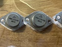
  • I upgraded the aluminum dome in the Radian 5208C to beryllium. The beryllium has very similar frequency response but sounds quite a bit different. Extremely clear and transparent. Sounds “buttery transparent” and not analytical. The tweeter just disappears.
  • I changed the tweeter wiring and several EQ settings in the DSP crossover.
  • I added Bass EQ options. The stock design is flat down to below 30Hz. This is great for small rooms and listeners who are not “bass heads.” However, if you push them super hard with lots of deep bass, the subs will complain. I added a “Rock and Roll” EQ setting that rolls off below 35Hz. With this setting you can play loud music in a large room and the speakers will handle the full dynamic range without effort.
Aluminum vs Beryllium

The standard version with aluminum dome sounds fantastic and I have no criticisms. Though the beryllium diaphragms cost several hundred dollars apiece, they are well worth the dinero. They deliver extreme transparency similar to ribbons and electrostatics, without harshness. The tweeters just disappear and let the music flow through. Finally, they’re not merciless. Many high-def speakers are harsh and unforgiving of ordinary recordings, but the Rolling Stones and AC/DC sound great too.

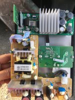
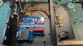
High SPL Drivers, Amps and DSPs

The Eminence 18 Kappa LF woofers produce 98dB SPL / 1W. The Radian 5208 coax puts out 95dB from the woofer section and ~100dB from the 16-ohm tweeter section.

High efficiency makes them extremely sensitive to electronic hum and noise. Amps with noise and grounding problems, not evident in typical 85-90dB audiophile speakers, are exposed. Furthermore, the MiniDSP 2x4HD has some noise which is not obvious with most speakers, but evident with high efficiency horns.

You can solve this by using an amp with an input control and turning it down a bit (Adcom GFA2535 is a great 4 channel amp and has level controls) or with a padding device like a Harrison Labs 12dB attenuator.

An even better solution is the MiniDSP Flex Eight, which has higher resolution and lower noise floor. I have configuration files for this too, discussed below. I further minimized the noise problem by wiring the rear tweeter (PRV WG175PH) and front tweeter in series, with parallel resistor networks bringing the total impedance down to 11 ohms. This tames the tweeter output to 95dB.

Only the most basic functions are performed by passive components: 200Hz crossover between woofer and midrange; tweeters are wired in series with an L-pad for adjusting level of the rear tweeter; a 20uF capacitor simply protects the tweeters from accidents. All heavy lifting is done by the DSP with 2KHz crossover with FIR phase correction.

image010.png


Noise sensitivity notwithstanding, the energy, dynamic range and effortless performance you get from efficient pro drivers like Eminence and Radian more than compensate for the noise precautions you have to take. Speakers with vast dynamic range and low distortion sound so effortless and open, you feel compelled to crank the volume up.

Most audiophiles are so conditioned to buckets of intermodulation distortion, they’re stunned when a system doesn’t have it. I call it “Dynamic range to burn.” Once you’ve experienced it, you never go back.

The “Lambda Slab” U-Frame

image011.jpg


The triangular sides on the bottom of the cabinet on each side of the 18” woofer pushes the dipole roll off frequency lower. Without them the roll off would start around 100Hz; with them it’s around 60Hz. The wings buy you almost an octave of bass.

It’s easy to get deep bass from an Open Baffle speaker… you just need a Digital Signal Processor and heavy EQ. You pay a price, however, which is that your woofer can easily bottom. Distortion spikes at low frequencies. I have paid close attention to this issue. The bass EQ begins in earnest below 60Hz. This is the curve for the standard “Jazz EQ” DSP file:

image012.png


Above: EQ reaches 20dB at 29Hz, then rolls off gently below. Yep, 20dB is a ton of EQ, but remember that these have 95-98dB sensitivity, so across 90% of the spectrum they require very little power. Extra power is only demanded by occasional deep bass passages.

I call this the Jazz EQ setting. It’s optimized for lowest group delay and least ringing in the step response. Most speakers have gobs of phase shift at low frequencies which you easily hear on well recorded bass drums. The steeper the filter, the more phase shift. Steep slopes like in actively assisted 6th order reflex designs add many tens of milliseconds of phase delay. This design sidesteps that.

image013.png


Above: Phase is +/-30 degrees from 40Hz to 20KHz with a max of only 120 degrees around 20-30Hz. Very, very few speakers match this. This cuts group delay and maximizes bass resolution.

image014.png


Above: Step response. Fast rise time followed by steady descent with no phase reversals. Drivers fire in perfect time with each other. There is little low frequency ringing because the design minimizes phase shift and group delay. Very few speakers match this. This is one reason why clarity and imaging are so precise.

image015.png


Above: Impulse response. Most speakers shred impulses, which should look like an upside down “T.” The Live Edge Dipoles deliver 80% of their energy in a tight 0.1 millisecond slice. This makes lightning fast transients and exquisite detail.

Bass from most subs, even celebrated designs, sounds more like well-articulated thumps than genuine instruments. Open Baffle speakers bring a welcome exception and sound extremely natural. The Jazz EQ setting achieves flat response to below 30Hz with minimum phase delay. Perfect for listeners with small rooms and / or do not demand the pantleg-flapping bass of car stereo shows and rave clubs.

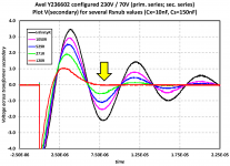
However if you have a big room and/or want to shake the house with loud rock or electronic music, I added a 2nd EQ configuration file called “Rock & Roll EQ” that adds a dual shelf filter (instead of standard high pass) at 35Hz, with a slight lift between 40-60Hz and above 5KHz:

image016.png


With this one tweak, the speaker can play 10dB louder than the Jazz setting. So if you like your music loud, even in a large room, this EQ setting will keep your woofers from bottoming or wincing in pain.

image017.png


Above: Low frequency drive signal from amp. Blue = Jazz EQ. Orange = Rock & Roll EQ. Reduces woofer excursion by 70%, allowing up to 10dB greater output.

This matters in an Open Baffle design. That’s because an acoustic suspension woofer’s max output falls at the rate of 12dB per octave. That is challenging enough if you’re trying to shake the house. But an Open Baffle woofer loses traction at the rate of 18dB per octave (12dB from standard radiation resistance, plus an extra 6 dB due to rear wave cancellation). So every 1/3 octave of bass you ask of an Open Baffle speaker demands +6dB which requires 2X the excursion and 4X the power. One full octave costs you 18dB: 8X excursion and 64X power!

By relieving the 18” woofer of everything below 35Hz, you buy yourself 10dB more dynamic range. The 18” Eminence woofers, bolstered by the U-frame wings and 35Hz roll off on the Rock & Roll EQ, use 14dB of boost at 39Hz and generate high SPLs without effort. You can load both settings into your MiniDSP 2x4 HD and switch between them at will.

Low Distortion

Below:
Distortion measured at mid-band output of 90dB SPL/1M in a real room; SPL climbs to 100dB at 40Hz. This is with the Rock & Roll EQ setting. Distortion is under 2% above 60Hz, under 1% above 150Hz. (Data also includes rattles and buzzes of the room itself.) The darker curve is 2nd order, lighter 3rd order:

image018.png


(continued in next post)

AEM6000 Based 100W Amp

This is a design I've had in use for rather a long time. It started life as a design exercise to see if I could do a more space-efficient board for my original AEM6000 based amps, as I wanted something that would fit on a 50mm high heatsink. It's a very, very close friend to my 50W version with a couple of extra output transistors and a bit of a compensation tweak. Along the way it changed a little from Tilbrook's original in topology, and rather a lot in component choice. It has better performance than my original design, both through a better tighter layout and also through the use of faster transistors.

I've built a few of these. Nowhere near as many as the 50W flavour.

Lots of component substitution is reasonable. I like to use MELF resistors, but that's mostly just bloody-mindedness. An exception is the feedback divider. No, it won't work with vertical MOSFETs.

I have checked just now, and every single component is currently (December 2020) available.

The design is free for use for non-commercial purposes.

In the design folder I have placed:

PDF file of schematic
PDF file of construction notes
Top and bottom layer stuffing diagrams
PDF file of parts list with supplier info
Gerbers and drill file for board manufacture.

Google Drive link to design files

IMG_1423.jpeg

3-way to active - Hypex FA253 - learning project

Hello, All!
Just joined today as I found a very useful guide here on using Hypex Filter Design, thanks to DannerD3H.

I have always been a music and audio fan and find acoustics and speakers particularly fascinating. I always wanted to design and build my own speakers but never got to it, mainly due to lack of space to use for woodworking (I live in a small flat). But still decided to go for it. I will work around the difficulties somehow. If there is a will, there is a way.

I have reasonable understanding of audio, electronics and design process and ok to use my hands, but I have almost no experience, so face a steep learning curve.

First thing I did is buy the Loudspeaker Design Cookbook. Reading it now. Learning curve.

I have a pair of old slim floorstaders (description to follow) that I intend to convert to actives. This will help to initially avoid much woodwork, while still learning about drivers, crossovers and amps and box interaction. This will be done in two steps:

Step 1 - add Hypex Fusion amp and use existing drivers and enclosure as is

Step 2 - replace the drivers for better specced ones, modify the box

This will hopefully take me to a future point of fully building larger speakers and maybe a sub. One day.

So far I have bought a Dayton UMM6 mic, a Fosi V3 amp and just about managed a few measurements in REW of the speakers in passive form and of individual drivers. I managed to install on old version of HFD software on an old Win XP (!) laptop and hope to use that to program the FA253s when they arrive later this week.

I do stumble a lot and have lots of questions and definitely need some help. I will be asking here and would appreciate any help from the more experienced members.

I will make a post with the existing speaker details and maybe a few other things I am struggling with.

FWIW I do have some forum history on a couple of HiFi forums: Hifiwigwam and Audiosciencereview.

So, wish me luck.

MarkAudio MAOP 11 single driver loudspeaker

http://www.fidelitatem-sound.jp/fidelitatem-NC/n_detail_NC11.html


Login to view embedded media

Product specifications​

  • Model: NC11_MOP_MC /NC11_MOP_MC
  • SP unit: MAOP_11 v2
  • Playback frequency: 35 Hz - 25,000 Hz
  • Maximum input: 35W (cont.)
  • Output sound pressure level: 87dB /1w@1m
  • Rated impedance: 7.2Ω
  • Mms = 7.90 g
  • Xmax(1way) 8.0mm
  • Dimensions: (width x height x depth) 245 x 450 x 295 mm
  • Weight: 11.5 kg x 2

Reducing the work on BC1 Bass/Midrange Driver

What is the best way of reducing the Bass - load on a pair of Spender BC1's to protect them from excessive transients when driven at high - ish levels?

Option 1 - A separate Bass Speaker Enclosure with crossover feeding the BC1's, without modification to their crossovers.

Option 2 - A separate Bass Speaker Enclosure, driven by a 405, with filtering at source to split drive between Main Amplifier and 405?

For Sale Babelfish J with Semisouth SJEP 120R100

For sale are 2 Babelfish J boards adjusted to 1,8A bias.
They are tested and ran for aprox 100h in my setup. They sound great!
With XLR inputs and Semisouth outputs.
And before you ask - yes, these are originals, I bought them directly from Semisouth when the company still existed 😉
You can buy it with or without the heatsinks. The heatsinks are thought for 80mm fans.
I would like to have €250 without and €300 with heatsink (without fan!) plus shipping costs.
WhatsApp Bild 2025-04-16 um 14.34.00_b6c2ce3f.jpg

WhatsApp Bild 2025-04-16 um 14.34.00_27243782.jpg

WhatsApp Bild 2025-04-16 um 14.34.00_c06a2d8a.jpg

WhatsApp Bild 2025-04-16 um 14.34.00_d74060bf.jpg

WhatsApp Bild 2025-04-16 um 14.34.00_dbfe1e35.jpg

WhatsApp Bild 2025-04-16 um 14.34.00_2d84d8be.jpg
  • Like
Reactions: schultzsch

T+A 1220R "no Disc"

Hello,

I have a T+A 1220R that always displays "no disc."
It doesn't even try to spin.
I can see the lens 2-3 times, but I can't see any red light.

I replaced the laser unit with a "new" one, but the error remains the same.

I then measured the LDON signal on the SAA7372, but it stays permanently low. That can't be normal, can it?

Unfortunately, the manufacturer doesn't provide any documentation about the device.

But maybe someone here can help.

Regards

Mario

Limestone turntable, help needed with motor and drive

IMG_2314.jpg
Dears,
This is second (and last) blast from the past project that I will publish. Its from early 2000's when I was very much into doing different audio things.
Other of my old projects have no much difference from usually seen executions, so I will skip those.

As elementary school kid (in 1977), my older sister left me her BSR turntable system (in Yugoslavia than called Tosca) and some 50LP's, good stuff of the time, Leonard Cohen, Dylan, Cat Stevens, Janis Joplin, Roberta Flack, Jimmy Smith, some classic and so on... Anyway, I felt in love with LP's and HIFI forever, this still goes on.
Anyway, few friends (actually their parents) had Thorenses, Sondeks and Duals, , I always wanted proper turntable. By the time I made my own money, CD came into play and I bought one of the first Philips CD player.
Few years after I still wanted TT, bought one crappy example, throw it away and decided to make my own. Intention was not to make hi end piece, but to make vintage looking TT similar to those that I was wishing for:
This is the result:

Kondo KSL-M77 phono preamp clone project

Kondo KSL-M77 phono and preamp clone project

Hey guys. It's been a while. 🙄

I got burnt out from audio and sort of took a break. Multiple reasons, and too many other things going on.

I recently put up some speakers for sale, and managed to find a deal with someone who wanted to make a trade. So for a pair of Aucharm full range 12" speakers I wasn't going to use, I got a B&K AVR 202 with hum problems, a vintage Trygon T50-2 power supply, and this KSL-M77 project. I'm happy with the trade, and it gives me some stuff to play with as I find the time. I should have a power transformer that would be suitable for this kit. Just in the value of the caps and enclosure alone I think this was a decent trade, even if I gut it and build something else without boutique parts or circuitry.

Does anybody happen to have details on these? All I really find is PCB photos but no real detailed specs on them. I'll post what I could find.

Looks like this is very close to my kit-
Audio KONDO AUDIONOTE M77 Line and Phono AMP HiFi Tube Preamplifier Board - Free Shipping - ThanksBuyer

Anybody recognize those pots used here? Looks like one volume, one balance, and a source selector.

IMG-20200813-171351082.jpg

IMG-20200813-171405705.jpg

IMG-20200813-171501376.jpg

IMG-20200813-171519036.jpg

IMG-20200813-171551141.jpg

IMG-20200813-171600626.jpg


I think this is the correct schematic. From what I can tell this sucker takes eight (8)! 12AY7 tubes!!??! I may see if I can modify it to take something like 6N1P or 6CG7 since I can mix and match those with some parts value changes.

52567-1.jpg

Suitable midrange cone, for bandpass mid in Unity horn

I'm looking for a midrange cone, up to 6.5"dia to fit into a Bandpass enclosure which will fire into an odd unity horn (odd because its being re-shaped to fit into a car, but its using the unity concept).

Basically (I think) I need a midrange driver with a relatively high Fs and low Qt, to work in a 4th order bandpass (sealed rear chamber and ported front) and give me a lower cut off of about 200Hz and upper cut of of 1400Hz (-6db) if I can get more bandwidth all the better.

I'd like to go for a single 6.5" driver or smaller, multiple 2" or 3" drivers would be quite acceptable. I would ideally like something that is available in the UK though, importing from the states is an option but something easily available would be prefered. Someone is having reasonable success with multiple AuraSound NS2 'Whisper' drivers, I'm looking at the Eminence Alpha6 as they are cheap and easily available. any other suggestions please?

Ported Tweeter

Erin Hardison made a video in 2023 of a ported tweeter. He said it was made by someone named "Alex" who was going to file a patent.

I haven't seen anything more on that since then, so I thought I'd take a crack at reverse engineering it.

1745303355734.png


This is the ported tweeter that Erin reviewed.

Pic is from his FB.

Go subscribe to his channel and buy your merch using his link: Login to view embedded media
Here's Alex's website: www.referenceacoustics.com

1745304337953.png


Here's a graph from Alex's website, illustrating the difference in SPL.

1745304704138.png


Here's a graph from Alex's website, illustrating the difference in excursion.

1745303600429.png

This is a ScanSpeak D3004/6600. For sale at Madisound for $228: https://www.madisoundspeakerstore.c...inator-d3004/6600-aircirc-tweeter-textile-dom

1745303559153.png


In order to make a Ported Tweeter, I believe Alex simply drilled holes through the faceplate, to allow the radiation from the rear of the diaphragm to "vent" through the faceplate.

Scan Speak hasn't published full Thiele Small for this tweeter: https://www.madisound.com/pdf/scanspeak/D3004_660000.pdf

But I think that's kinda irrelevant. I have an idea of how you could port it:

Basically, you buy a set of drill bits, and then you drill progressively larger ports, until you get the frequency response you're looking for. As with any ported box, you can trade efficiency for bandwidth.

If you don't want to spend $230 on a tweeter, this "trick" should work with any tweeter that you can expose the back side. IE, if the magnet is solid, it won't work. But most of the 1" and 1.125" SB Acoustics Tweeters, they'll work. I used the SB29ADC in my experiments with metamaterial absorbers:


What makes cymbals sound real?

Some time ago, I was walking on a parking lot and heard music coming from the adjacent building 20 meters away. Its doors were open. What struck me, was that I could hear that the cymbals sounded like the real thing, without being able to see what made the sound. It turned out to be a dance organ. In a large, reverberant room.

For those who do not know what a dance organ is, it is awesome:

Login to view embedded media
Now, I am curious why it was clear that a real instrument was playing and not a loudspeaker.
  • Can it be related to an instrument being 'faster' than the same instrument, recorded and played back over a loudspeaker? I do not think this could explain it here, because there only was a mix of reflected sounds to hear.
  • Can it be related to directivity pattern? I doubt it. There is no way to distinguish between different directions. All I knew was that sound was coming from some doors 20 meters away.
  • Can it be the sound pressure level? Real cymbals are loud. But it was not that loud outside.
  • Can it be the dynamics? Real instruments have no compression applied to them. Maybe?
  • Can it be the spectral content of the sound? Being outside of the building, I must have heard the power response. Cymbals are quasi-omnidirectional over their full frequency range, while most loudspeakers beam at high frequencies and have a downward trend in their power response. But would not have it been altered to an unknown amount, by the room acoustics?

Any thoughts are appreciated.

DIY midtweeter planar, physically curved and shaded to be used in a dipole CBT

Thanks to all the amazing help I got in my first thread musing about flexible PCBs (and why not to do it) I decided to scrap my requirements and start again.

My new requirements are:
  1. Single planar driver, 160 cm tall.
  2. Good frequency response, no ugly dipole peak allowed.
  3. Physically curved with a 75 cm radius.
  4. Shadeable, ideally as an internal part of the coils but splitting the coils into multiple separate parts that can be driven separately would be OK.
  5. Can cover from 300-400 hz (24 dB / oct crossover) up to 20 khz.
  6. Can output 100 dB @ 1m across the operating frequency range without too much distortion.
  7. Comparable horizontal dispersion to a Neo3W, limits horizontal radiating area to ~ 35-40 mm wide in the treble.
  8. Should behave as a single driver with vertical CTC of at most 2 cm. I want to avoid vertical lobing.
  9. Manifacturable with a 3d printer + using laser cut plywood.

Basically I want the perfect purpose build planar driver for my new dipole CBT which will look very similar to the old one 🙂 but with a planar as the main driver instead of full range 2.5"cone drivers. I'll still use cone drivers for 80-400 hz but I'm planning to hide them behind the planar in the spine of the speaker.

I will at least initially use 12 micron mylar & 30 micron aluminum foil. I will cut the foil on a silhouette cameo 4. I think I will need ~ 1 mm clearance between traces of the coil but I'll have to test that when I get parts & the machine. But since others here on the forum has done this already I'm not that worried and it will probably work just fine.

I also have plans to Corrugate the membrane lengtwise like this to stiffen side-to-side resonances. And then mount it top and bottom while floating (with foam) at the sides to reduce resonance frequency.

There are lots of small desicions I need to but for now the next open question is:

How should I setup my magnets?​

I'm tossing around ideas for 4 configurations. Since I like tinkering I might just build all 4 and then measure them and see which one I like the best.

The 3 lengthwise setups are pretty normal. Just a question of how big the gap between the magnets can be without it impacting performance. My gut says that of course the 7 magnet setup will measure better in the treble but how much better and would it be significant? Having only 3 rows of larger magnets would probably be much easier to build. Since I wont have a metal front plate I'd have to get creative making a strong enough frame that I can print. But should be solvable although I might need to add more frame around the magnets to help support them.

The magnet-sideways mounted setup is kinda weird but would have some distinct advantages: It would be easier for me to manifacture on my 3d printer while at the same time having less support since I can rely on the magnets themselves for mechanical support. It would also probably measure extremely smooth in the vertical axis since it is extremely uniform thus should have an effective minimal CTC.

It does have some glaring disadvantages though: I'd have to come with some way to ensure that all the magnets and the coils are in alignment which isn't a trivial problem to fix. I'd also have to get creative when corrugating the membrane since all the corrugations would need to be uniform along the whole length. Also, it would be slightly less efficient due to the coil twisting more. It would, however, be fun to try to overcome the engineering challenges and build it anyway 😆

MagnetMusings.png


Next step​


First is waiting for materials but then plan to build and test prototypes. My plan is to build 20 cm tall prototypes since the main thing I want to test is how the different setups perform in the horizontal axis + how easy they are to manifacture and how mechanically stable they are. Or basically how much extra support do I have to add to make it not fall apart, less is better.

The design which measures good enough while also being easy enough to manifacture will be the winner 🙂

recommend a nice mid-budget over ear with noise cancelling?

Hello friends

as the title says, I am looking for a nice, mid-priced ( < 500.- ) over-ear headphone with noise cancelling, as birthday present for my better half... I am not really into HP, although they sometimes come in veery handy. She's not admitting to be into audio (listening through laptop/handy and other calamities, but let's ignore this for a second)

I personally would go after soundquality first, she OTOH weighs the aesthetics rather high (me too, but second to sound)...

If I'm right, the usual suspects are apple's things, bose and sony? Anything but them?

Thank you

:cheers::

For Sale Pass A40

I remember very well when the A40 was presented in AA/78. Gee, that’s a healthy while ago! Evil tongues might even mention generations.

Ok, the years to follow have been filled with what they have been filled with.

Short story, I never got around to build one, and now it’s time to pass, pun intended, it on.

You get two new boards, NOS (with golden legs) MPSLs, and used, original, Lambda output TO-3s.

2N5248 and the other components you have to supply yourself.

$200 + shipping at cost.

R

Attachments

  • IMG_1175.jpeg
    IMG_1175.jpeg
    407.8 KB · Views: 299
  • IMG_1176.jpeg
    IMG_1176.jpeg
    277.3 KB · Views: 283
  • IMG_1177.jpeg
    IMG_1177.jpeg
    301.5 KB · Views: 252
  • IMG_1178.jpeg
    IMG_1178.jpeg
    408.2 KB · Views: 278
  • IMG_1179.jpeg
    IMG_1179.jpeg
    465.5 KB · Views: 326
  • IMG_1180.jpeg
    IMG_1180.jpeg
    635.4 KB · Views: 321
  • IMG_1181.jpeg
    IMG_1181.jpeg
    321.8 KB · Views: 337

Simple, no-math transformer snubber using Quasimodo test-jig

A power transformer snubber is a wonderful thing for reducing or eliminating RFI from rectifier-induced LCR ringing. Unfortunately it's a huge pain to design and optimize a snubber. First you have to measure the transformer's leakage inductance and secondary capacitance, at about 100 kHz, which is not especially easy. Then you have to estimate the capacitance of your rectifier(s), which does not always appear on datasheets. Finally you plug these numbers into a formula that spits out snubber values -- and then you hope it's all correct.

Shown here is a little test jig called "Quasimodo the bell-ringer" which makes this process a great deal simpler. Quasimodo connects an actual snubber across the transformer, smacks the transformer to make it ring, and you observe the ringing on an oscilloscope. Then you adjust a (25 turn) potentiometer on the jig, watching the scope to find the setting which completely damps out all ringing. And you're done! Just use the same snubber values in the end product, as you used on the test-jig, and success is yours. (The 25 turn trimpot is socketed for ease of measuring the final resistance that gave perfect damping).

Attached are some scope waveforms showing a Quasimodo jig driving an Avel Lindberg toroidal transformer (from the Akitika GT-101 power amp). I set the trimpot to 5 different resistance values, and got the 5 traces shown. When the trimpot was removed from its socket (R = infinity), I got the black trace. A setting of Rtrimpot = 109 ohms (red trace) gave "critical damping" with no ringing: see yellow arrowhead.

Quasimodo gave an optimum snubber having critical damping (Greek letter zeta = 1.0), without requiring any calculations and without measuring the transformer's inductance or capacitance. It is a quick procedure, too: set Rtrim to max, observe waveshape on scope while reducing Rtrim, stop when all ringing is completely damped out, remove Rtrim from socket and measure it with an ohmmeter. About 3 minutes from start to finish.

This Avel Lindberg transformer has dual primaries for 115V/230V operation. So I configured the primaries the other way and ran Quasimodo again: figure attached. Not surprisingly, the optimum snubber for 230V operation is (slightly) different than the optimum for 115V operation: 120 ohms versus 109 ohms. Plus or minus the error tolerance of my ohmmeter, of course!

I've also attached a .pdf note that contains more details, schematics, construction tips, user guide, more "Quasimodo in action" scope photos, plus a bit of theory and a list of references.

EDIT 1: I had a small number of extra PCBoards + kits of all parts, which I sold at my cost, in October - December, 2013. They are all gone now, and I have no plans to sell any more. I encourage any energetic and enthusiastic diyAudio member to organize a Group Buy, using the PCB Gerber files and Bills Of Materials I provide in this thread. "CheapoModo" (a low cost version of Quasimodo) kits and PCBs are available in the Vendor's Bazaar, here.

EDIT 2: I have attached the PCB Gerber files and the Bill Of Materials, for both boards (V3_SMD, and V4_thru_hole) right here, to post #1. So now they are very easy to find!

EDIT 3: (April 2022) I just stumbled across this "Yes Math!" application note from Texas Instruments, which calculates RC snubbers to eliminate ringing from switch mode power supplies: (link)

EDIT 4: If you don't yet own an oscilloscope, post #2540 of this thread shows a cheap (USD 40) little scope toy which works for Quasimodo.

EDIT 5: Answers to frequently asked questions:

  1. Build guide for V3 (SMD) is found in post #27
  2. Build guide for V4 (thru hole) is found in post #103
  3. 2 hour build time, quick-and-dirty Quasimodo on solderless protoboard (no PCB!) is found in post #18 and in (the CheapoModo thread)
  4. Substitute parts recommendations are found in the Bill Of Materials
  5. How to choose a MOSFET besides the ones in the BOM, is found in post #175
  6. How to check your own BOM before purchasing components, is found in post #203
  7. diyAudio members who have ordered their own sets of PCBoards from a PCB fab, using the Gerbers provided here, include: gazzagazza, luvdunhill, Borges, stormsonic, cwtim01, normundss, dsolodov, EUVL, kissmurphy, stephengrenfell, Piersma, SyncTronX, yoaudio, andrensairr. You can PM them to find out how easy or difficult it was.
. .

Attachments

Alpha Nirvana 39w 8ohm Class A Amp

Hugh has been doodling on LTSpice and he came up with something really extraordinary: a 43% efficient SE Class A amp that can drive 39w into an 8ohm load with the usual Aksa-approved harmonic profile and low phase shift. The amp uses only 6 bog-standard actives and employs the excellent Aksa Lender front end to drive what seems like standard complementary MOSFET output stage using the venerable and easy to find IRFP240 and IRFP9240 outputs. However, it is not a push-pull amp though, but operates in SE Class A with an active CCS controlled by a cleverly wired PNP CCS controller. Please note that this active CCS is no longer based on the Pass Aleph topology but a PNP-controlled P-channel with symmetric sense resistors. The amp should really be called an Aksa Lender Nirvana.

So we have 4x TO-92's, and two TO-247 MOSFETs. Together, with only a +/-27v supply, they combine to make 39w into 8ohms with a predicted 0.019% THD AT 12w, and of course, always dominant H2 and a monotonically decreasing higher order harmonics. Output impedance is predicted to be less than 50mOhm at 12w into 8ohms at 1kHz and DF is 160. Quite a powerful amp given the rather low 27v rails. 27v rails happen to be what you get when you use an SLB PSU with a 22v trafo like an Antek AS-3222. Gain is 28.5dB, and phase shift is only 5.3deg at 20kHz.

Here is the rough schematic from LTSpice:
790838d1572288561-alpha-nirvana-39w-8ohm-class-amp-alpha-nirvana-schematic-v1-jpg


More detailed analyses and sims to come...

Later to be followed with the usual P2P vero-build, and then hopefully, a real PCB verification build and full measurements.

Enjoy!

A huge thank you to Hugh for continuing to give us these gems! :cheers:

Edit Sept 21, 2023: Looking for Cliffs Notes on the BOM and some and hints on what parts to use etc by Voiceofposeidon here: https://www.diyaudio.com/community/...8ohm-class-a-amp.344540/page-107#post-6920076

Edit May 25, 2020: detailed O-scope max power clipping tests by AndyR using his 4-ohm variant Alpha Nirvana with +/-21v rails:
Alpha Nirvana 39w 8ohm Class A Amp

Short story - good for 34W into 2.1ohms loads! Not bad for true Class A amp (cannot ever go into Class AB - it simply softly clips when pushed).

Edit Oct 31, 2019: latest version 2 schematic of amp
791336d1572501676-alpha-nirvana-39w-8ohm-class-amp-alpha-nirvana-schematic-v2-jpg


Predicted FFT with v2 for 2.83Vrms into 8ohm, THD=0.0039%:
791338d1572501676-alpha-nirvana-39w-8ohm-class-amp-alpha-nirvana-v2-8vpp-8ohms-fft-jpg


And if we increase power to about 12.5w into 8ohm, we still see a nice monotonically decreasing harmonic distortion profile. THD is now about 0.016%:
791339d1572502081-alpha-nirvana-39w-8ohm-class-amp-alpha-nirvana-v2-28vpp-8ohms-fft-jpg


Edit Nov 27, 2019: Measured max output before clipping is 51.6vpp into 8ohms, or about 41.6w into 8ohms. This is with +/-28.5v rails.

797233d1574584334-alpha-nirvana-39w-8ohm-class-amp-build-prototype-completed-main-01-jpg


797481d1574673293-alpha-nirvana-39w-8ohm-class-amp-sound-00-jpg


797514d1574693319-alpha-nirvana-39w-8ohm-class-amp-sound-06-jpg


797995d1574862995-alpha-nirvana-39w-8ohm-class-amp-alpha-nirvana-51-6vpp-8ohm-clipping-test-scope-jpg


Edit Nov 29, 2019 - Grounding scheme schematic (post 279):
798443d1575030654-alpha-nirvana-39w-8ohm-class-amp-grounding-schematic-built-v2-jpg


Produces background noise FFT like this:
798444d1575030654-alpha-nirvana-39w-8ohm-class-amp-bkgnd-grounding-improved-jpg


Some measurements at 3.16vrms into 10ohms with a Cayin N3 DAP as 1kHz osc source, obtained 0.0041% THD and mostly 2nd and 3rd harmonic:
799462d1575395857-alpha-nirvana-39w-8ohm-class-amp-3-16vrms-10ohms-cayin-n3-fft-jpg


GB thread for this amp here:
Alpha Nirvana 39W SE Class A Amplifier GB

Tips and tools on how to do professional clean looking SMT/SMD soldering:
Alpha Nirvana 39w 8ohm Class A Amp

Edit Dec 14, 2019: BOM in easy to read .XLSX format: https://www.diyaudio.com/forums/att...8ohm-class-amp-alpha-nirvana_bom_001-xlsx-zip
Mouser Shopping Cart for BOM here. Do not modify cart - please save to your own shopping cart as a new project before changing.

Edit Jan. 3, 2020: please note that the Mouser shopping cart above needs to have parts for snubber boards increased by 2x as there are parts for 1 board only. The BOM is for one amp board so needs to be doubled for stereo. Double following: (R1001, R1002, C1002, V1001)

Edit Dec 26, 2019: AndyR did a lot of due dilligence to put together a very nice BOM for both the 8ohm and 4ohm versions of this amp here:
Alpha Nirvana 39w 8ohm Class A Amp
Thank you, AndyR!

Edit Apr 24, 2020 - Dual Monobloc Connection Diagram is using SLB and SFP boards:
837360d1587747684-alpha-nirvana-39w-8ohm-class-amp-a190389f-cdd0-45c7-8d35-354511cdef86-jpeg


As built schematic verified and tested to work:
799467d1575397209-alpha-nirvana-39w-8ohm-class-amp-proto-schematic-built-dec-3-2019-jpg


Edit Apr 19, 2022: beautiful build by Steve (Sledwards12375):
top_iso-jpeg.1046306


Edit July 12, 2024: @AKSA said in this post that 2.2A quiescent current is needed for 4ohm variant of this amp. So size your trafo accordingly.

Attachments

  • Alpha-Nirvana-Schematic-v1.jpg
    Alpha-Nirvana-Schematic-v1.jpg
    210.7 KB · Views: 43,259

Output transformers for DACs

Hello everyone who looking for Sound!
:wave:

After years of expirience the output transformers for current and voltage output DACs have been developed. Transformers tested with following DACs: ES90x8S/K2M/PRO/Q2M, AK4x9x, PCM56/58/63, PCM1702/04, AD1862/65, PCM1792, PCM1794A, TDA1541/43, DSC dac and others. Speaking in general, transformers can be suited for any current or voltage DAC both in SE or PP modes.

These transformers are made on high permeable cores, have the low DC resistance at desirable inductive impedance to achieve the best frequency response of the DAC. Transformers provides significant sound quality improvement compared to other output versions. Your music will begin to live a new life, it will sparkle with a naturalness without plastic nervousness 🙂

25GHrhC


D60 trafos.
Transformers I/V stage for iancanada DM9038Q2MPi DAC
1675168366489.png1675168857503.png1675168905879.png

Transformers I/V (V/I) stage Twisted Pear Audio Buffalo-IIISE PRO DAC
PXL_20230209_032233778.jpgPXL_20230209_033610984.jpg
1675168944940.png1675169033581.png1675169590255.png


D46 trafos:
1675169440982.png1675169176721.png
1675169095665.png1675169130661.png1675169746929.png

The simplest way to connect my transformers to your circuit without soldering directly to pins (sometime DIYers wants to try different types in quick manner for example) is to use receptacles from Mill-Max:

1-st way is using receptacles with the soldered to them wires. PN is ED90595-ND
receptacles.jpg

2-nd way is using through-hole type of receptacles for PCB (PN is ED10169-ND):
PCB_receptacle.jpg


Here are some impressions from iancanada IanCanada's Latest RPi GB Goodies Impressions... and your tweaks, mods and hints...

And here is the page from Andrea Ciuffoli: DSC Output transformers test

Dimensions D46 type: OD=46mm, H=24mm
Dimensions D60 type: OD=62mm, H=30mm

Frequency Responce of transformer with ES9038q2m at 1.4VRMS (~8kOhm in secondary loaded on 100pF cable): 20Hz=-0.3dB, 20kHz=-0.2dB (rel.1kHz):
ES9038_4Vpp_1m_cable.png

Same, but with 470pF in parallel with secondary:
ES9038_4Vpp_1m_cable+470pF.png

The possible output level and the LF losses are depends on the output current of the DAC (and I/V resistance).

Here is an example of connection:
common_circuit.JPG

Here you can find prices and all the contact info: https://ivxformers.com

Lead time depends on existing orders. Thanks.

The relevant current documentation for my transformers available here: Output transformers for DACs

Attachments

USSA-5 Build with Review

USSA-5 build and review:

Amplifier Design/layout: Fab (The Great and Powerful Ape)

Amplifer PCB Layout: Alex

PSU Design/Layout: Project16

PSU PCB Production: Prasi


I couldn't stop thinking about this amplifier. The obsession began with a few fleeting traces of it's existence. The few members that have actually completed it were mostly silenced by its greatness. When I had enquired about it, people simply said "Oh, the USSA-5? It's the best amp I've ever heard."

I had to build it. But, the great mind that designed the amp wasn't going to just give me the boards. I offered to build a children's wing at his nearest hospital in his name. He said no. I said I would make huge donations to wildlife preserves around the world. He still said no. He was like talking to Willy Wonka and I was Charlie Bucket. I needed a golden ticket....

In the end, what worked was honesty and a promise to do two things: to build the amplifier and write a review.

So, here it is.

Soft as a Feather Pillow (SFP) SSR Soft Start Circuit GB

Jhofland and I are pleased to introduce the long-awaited Soft as a Feather Pillow (SFP) solid state relay (SSR) soft start circuit for use with power amplifiers. The development for this circuit has actually been going on for a long time, you will notice that the board design is at v2.1.

The goals of this circuit were to provide a gentle in-rush current limiter using a bank of power resistors during initial turn on, and then having a low Rdson MOSFET bypass the resitors after a set amount of time. By using a SSR vs a mechanical realy, we eliminate a source of arcing and wear, and the switchover is silent - no clacking of relays. Another goal of this circuit was to provide an added benefit of providing an open collector logic signal that can be used in conjunction with a speaker protection SSR that will tell it to instantly shut the speakers off if the voltage rail of the small on-board 5v SMPS turns off.

A special SSR ultra-low Rdson MOSFET was chosen that is rated for 600v, 23A, and has an Rdson of 22mOhms. This SFP can basically soft start almost any power amplifier in DIYA. With a low Rdson value of 44mOhm for two in series, we will have very low dissipation for even higher bias current Class A amplifers. The MOSFET is controlled with the usual opto-coupler and the start on time delay is controlled by a selectable RC circuit and comparator. Variable turn on time delays ranging from 0.5 sec, 1 sec, and 2 seconds is available via a jumper setting.

Here is the schematic:
821058d1582964599-soft-feather-pillow-sfp-ssr-soft-start-circuit-gb-sfp-v2-1-schematic-png


Edit Mar 3, 2020 revised v2.3 schematic with NTCs instead of resistors:
attachment.php


BOM for v2.3 here:
https://www.diyaudio.com/forums/attachment.php?attachmentid=821923&d=1583218278

Here is the verification unit undergoing testing with the Omega amplifier:
https://www.diyaudio.com/forums/att...soft-start-circuit-gb-sfp-v2-1-test-setup-jpg

Here is a closeup of the board in action:
821060d1582964599-soft-feather-pillow-sfp-ssr-soft-start-circuit-gb-sfp-v2-1-closeup-jpg


At turn-on, about 52Vac is registered across the four 100ohm (5w ea) wirewound resistors:
821061d1582964599-soft-feather-pillow-sfp-ssr-soft-start-circuit-gb-sfp-v2-1-test-52v-jpg


2 seconds later, the SSR kicks in and the voltage drops to about 92mVac:
821062d1582964599-soft-feather-pillow-sfp-ssr-soft-start-circuit-gb-sfp-v2-1-test-92mv-ssr-jpg


A clamp on current meter showed that the amp was drawing 1.62Arms at the wall plug. So the dissipation across the MOSFETs is only about 150mW. An earlier

I will continue testing out over the next few days to ensure tha everything works out well.

Edit Dec 17, 2023: including the schematic and BOM to the latest variant called the SFPP (SFP Plus) which includes remote turn on/off with a momentary SPDT switch with LED indicator. Great for low voltage front panel power switches with ring LED.

https://www.diyaudio.com/community/...ssr-soft-start-circuit-gb.350441/post-7538507

IMG_9811.jpeg

Attachments

  • SFP-v2.1-Schematic.png
    SFP-v2.1-Schematic.png
    155.9 KB · Views: 7,809
  • SFP-v2.1-Test-Setup.jpg
    SFP-v2.1-Test-Setup.jpg
    460 KB · Views: 1,265
  • SFP-v2.1-Closeup.jpg
    SFP-v2.1-Closeup.jpg
    398.4 KB · Views: 6,810
  • SFP-v2.1-Test-52v-turn-on.jpg
    SFP-v2.1-Test-52v-turn-on.jpg
    371 KB · Views: 6,656
  • SFP-v2.1-Test-92mV-SSR-on.jpg
    SFP-v2.1-Test-92mV-SSR-on.jpg
    430.9 KB · Views: 6,564
  • SFP-v2.1-BOM.txt
    SFP-v2.1-BOM.txt
    850 bytes · Views: 482

Capacitor quality in 3-way crossovers, different size capacitors, externally mounted upgradable crossovers... And other questions (Anthology II build)

Hi! Before I go into the Anthology build, I'm trying to first carefully calculate costs and predict possible ways in which I should go.
To start off, I have some questions:
1. For building the crossovers, I have found out that Jim stated in his plans that the tweeters should have 8.800uF capacitors. I assume he means 8.8uF (European notation is a little different with , and .) but I find no capacitors of such size. Should I therefore buy 2 capacitors and try to find ones that would add to each other to get exactly that measurement? Or should I rather buy 9.0uF or 8.2u F?
2. I tried to find some objective talk on which parts matter in quality and which don't (like super expensive cables which is propagated by a lot of people, so I don't know who to trust with capacitor quality). Could someone guide me on which parts matter? Capacitors, resistors, inductors... I'm trying to be on a budget but since I'm building Anthologies... I can spend a bit more on these electronic parts if it really is worth it. I saw some people claiming they hear differences between high grade capacitors of different lines and some claiming that as long as the quality is good (like ClarityCap PX), it's not worth paying more because there will be no difference. If it makes a difference, which ones are worth upgrading? I see people usually get these 82uF ones cheaper like ClarityCap PX or even Audyn Q4 (that would reduce the cost dramatically). Where does it make a difference? Will it make a difference where the capacitors are wired between signal wire and ground? (Woofers and mids have these 82uF capacitors mounted like that, the 8.8uF and 20uF are directly on the signal line)
3. Can I purchase capacitors of a reputable brand like ClarityCap and assume the capacitance will be correct without having to buy 5x more parts and picking ones closest to each other? Will that also work for Audyn?
4. If the components do matter, would it be possible to make an external upgradable crossover so I could switch these parts to better ones later on? As far as I understand, when I glue the speaker and install drivers, to upgrade the crossovers I would have to remove the drivers? Which are blocked by the front baffle? I don't understand the purpose of dual baffles sadly, could anyone explain how these are mounted? I thought the front baffle would cover the drivers but it seems it doesn't, so what purpose does it serve?
5. Could someone recommend me some inductors and resistors that I could buy in Europe or from China? Madisound wants 250$ for shipping to EU...

Thanks in advance! I hope to find some knowledge here, the entire thing is very confusing to me as of right now... Sorry for the question dump 🙁

Measuring DC offset on A Hypex NC500 based Class D amp

So I upgraded the Nord Rev D buffer board in my Hypex NC 500 based amp with Sparkos opamps and 15v Sparkos voltage regulators. I decided to measure the DC offset at the binding posts with no load and nothing connected to the inputs. My meter started at 20 mV and over the next 10-15 minutes settled out around 350-400 mV. The range would fluctuate by some 30 mV consistency after 15 minutes and never stabilize. Obviously this seems like a very high number and it concerns me. I never checked the amp’s DC offset before the upgrade.

Should the amp be under load for this measurement? I can pick up an appropriate resistor if needed. Also, should I have the amp’s inputs connected? Thanks for any help guys. I don’t want to hook up my speakers until I know the amp is safe. The voltages check out fine and the regulators are holding a steady 15vdc +/- on the buffer board.

Miscellaneous designs - Markaudio, Fostex, TB, Dayton, SEAS etc

As per the title really.

I work up far more designs than I usually publish on the forum or ever normally see the light of day elsewhere. Some were done at request, some are simply quick design exercises or checks / investigations, some I can't actually remember the reason for doing. I don't always have time to systematically catalogue things, and they can end up lying around on one of my HDDs for months until I sort through them. I'm currently in the process of going through one of my old external USB HDDs before it's recycled & found quite a few. Most weren't worth bothering with, but there were some more practical / interesting ones so rather than scrapping them, I thought I'd start a thread that can essentially be a bit of a dumping ground for misc. designs that I've done that either haven't found a home elsewhere, or that have previously been posted but got buried on other threads, so at least they're concentrated together.

Advance warning:

-There is little consistency in the layout / sketches. I'm lousy at CAD, and there's no way I can inflict more than a small portion on the long-suffering Dave to draw. In these cases, it's probably not worth a high quality drawing anyway. I've quickly re-saved most into png format to save space & done a little tidying if needed. The rough date is sometimes mentioned, sometimes not, depending if I remembered to add it at the time. Sometimes damping is shown in the sketch (all done in Windows Paint so they are very basic), sometimes it isn't, but I always refer to it in any accompanying notes. Same for bracing or vents / ducts; I often don't show the dimensions but they're in the notes. There may be some errors; I don't think there is anything major though. Normally I work in Imperial & assume a baseline 3/4in build / sheet material thickness. Some are metric, in which case the assumption is 18mm. Change as desired, providing the internal dimensions are not altered.

-Most of these are physically quite simple; vented box variations, some MLTLs or ML-Voigts etc.

-I'll add periodically as / when I find things. All are free for personal use.

CNC made WN300ALO horns (picture heavy thread)

This is the next step from the plastic horn I made as the very first prototype: https://www.diyaudio.com/community/...-neile-alo-horn-by-sphericalhorns-net.390581/

In this thread, I would like to show the workflow. I really enjoy watching other people's work, so I hope you will enjoy this thread as well. First, some overall data. The horn is ca 64 cm wide, 47 cm deep and 29 cm high. Each is made of 16 layers of 18 mm birch plywood and weights around 20 kg (estimate, did not weigh one). One horn needs two 1500 x 1500 mm sheets with a bit of leftovers. In total, the plywood bought was over 120 kg of material.

The workflow need to fit my hobby CNC. First, I cut all the single layers and rough the 3D parts. This was done by a 1/8" milling bit. Then, the layers are glued by two together and machined with the finishing pass with 6 mm bit. Glue up of the dual slices follows, during the project a friend of mine developed a unique press using water pressure to clamp the curved surfaces perfectly together. Then it is sanding, sanding and more sanding, gluing the two halves together, fitting the driver flange and more sanding.

IMG_6899.JPEG

Ready to start round one.

IMG_6901.JPEG

The slices are arranged to minimize waste.

IMG_6905.JPEG

Another layer cut.
IMG_6928.JPEG

Glue the two roughed layers together.
  • Like
Reactions: stv and docali

Cannot determine cap polarity from this wiring diagram

Hello all, long time listener first time caller. So as a hobbyist I finally decided to get one of those diy kits from China thats loosely based on the marantz 7c. I have made some modifications but my problem is with this wiring diagram. I can read them OK but Ive never seen electrolytic capacitors shown thiis way, just hanging there. Specifically the top 3. What is the polarity? If I was to guess, positive to 1 and 6 (12ax7 triodes), but I hate making things explode so I thought Id ask people smarter than me. I'm sure this is a rookie question, but ive searched a lot and dont see anything like it. Is positive to both sides and that shorthand for nagative to ground?
1000000644.png

Hello from Italy

Hello to everyone in this forum, I'm Eduardo, 25 years old from Italy! Nice to meet you. I've been reading this forum and found a lot of interesting arguments and knowledge. I have a strong passion for electronics, and i'm currently trying to repair my grandfather's old Rega system. I'm looking forward to learn new things!

ROKSAN ROK L2/S1 Pre-and Power Amp - Schematic and PCB Images wanted

For performing any modification steps I want to have the genuine circuit diagrams. Maybe one of the member can upload this.
in post #51 under
https://www.diyaudio.com/community/threads/2sj49-2sk134.1188/page-3
is mentioned, that one of the most used circuits was choice for the power amp.
This URL in German I have found concerning this models
http://www.hifi-forum.de/viewthread-84-24940.html

Attachments

  • 1760490-6a971f64-roksan-audio-roks1-vintage-audiophile-power-amplifier-in-good-working-condition.jpg
    1760490-6a971f64-roksan-audio-roks1-vintage-audiophile-power-amplifier-in-good-working-condition.jpg
    130.4 KB · Views: 234
  • a.jpg
    a.jpg
    56 KB · Views: 247
  • 1760492-488a26fc-roksan-audio-roks1-vintage-audiophile-power-amplifier-in-good-working-condition.jpg
    1760492-488a26fc-roksan-audio-roks1-vintage-audiophile-power-amplifier-in-good-working-condition.jpg
    92.3 KB · Views: 208
  • b.jpg
    b.jpg
    64 KB · Views: 240
  • 1759406615_g.jpg
    1759406615_g.jpg
    142.2 KB · Views: 220

Chassis hunt

Hi,

Looking for chassis that are similar to what's being sold here in the store. Mostly interested in 4U and 5U and compatible with F4, F5, F5T, F6, Aleph J...

I'm in Canada (Toronto) so preferably something that can be ordered from a Canadian vendor to avoid import duties and costly shipping.

Any clue where to look for these? Any help is greatly appreciated!

Thanks! Cheers!

Pioneer PD-91 Playback Issue: Disc Won't Spin Flat, Starts at 45° - Is the PWY 1004 Laser Dead?

Hello everyone,


I’m encountering an issue with my Pioneer PD-91 CD player. When it is flat, the disc doesn’t spin when I press "play," only a slight movement is visible. However, as soon as I place the player on its side (about a 45° angle), the disc starts spinning normally and playback works perfectly. Once the disc has started, I can place the player flat again, and it continues to work perfectly without any issues 😕.


I’ve cleaned the lens, but the problem persists. Could this indicate that the PWY 1004 laser is dead, or could it be another issue (spindle motor, alignment, clamp mechanism, etc.)?


I would love to hear if anyone has experienced a similar problem and if you have suggestions on any adjustments I could make to improve the situation. Are there any settings or simple repairs I could try before concluding that the laser is faulty?


Thank you in advance for any advice and feedback!

Attachments

  • IMG_5117.mp4
    193.1 KB
  • image.jpg
    image.jpg
    346.2 KB · Views: 17

A new thread for lightbulb loaded amplifiers.

Since the de lite thread is archived i decided to start a brand new thread for lighbulb loaded amplifiers.

I'll start and i present you the "De broke" an cost cut version of the delite using a darlington transistor and a car turn signal lightbulb (that was cheaper than a headlight one and has a diffrent glow) and running on 12V making a whopping 1,5W of power at 8 ohms.

IMG_20250421_221844.jpg

IMG_20250421_222308.jpg
  • Like
Reactions: gijser

SEAS 29TTFCD/G H1500-6ohm

A few years ago I purchased some drivers from PartsExpress, and one of the drivers were these Seas H1500 tweeters.
The PE part number was 299-760 and stated "Seas H1500 1" Aluminum", and the sticker on the side shows "29TTFCD/G H 1500-6ohm. Made In Norway".

I can't seem to find any spec sheets on this specific driver though? Does anybody know more about this driver, or have a copy of the spec sheet/pdf file?

Thank you

Tweeter repair, Shellac vs Damar?

Yesterday I got lucky, scored a pair of roadkill KEF C40s.

Unfortunately, the tweeter coatings are dodgy, almost completely dissapeared on one, highly cracked on the other.
Careful work with Shellite (What us in Aus call Naptha) got the remains off.

So, the next step is to re-coat them, following the ideas in this thread:
https://pinkfishmedia.net/forum/threads/restoring-kef-c40-loudspeaker-system.293967/

But it occurred to me that I could use Damar varnish as an alternative to Shellac (I have both), however neither are ideal; I assume both will set hard, whereas the original coating appears to have been somewhat flexible. Opinions?, comments?, Alternatives?

(if the worst comes to the worst, I have other alternatives I could use behind the original KEF faceplates. Plan is to restore them to original to see how they sound, more to come whn I've got some pics & measurements sorted)

Signalyst DSC1

The author of HQplayer Jussi Laako released design of this dac on Apr 18.
It's a pure DSD 1-bit 33-level dac with full support from HQplayer.
Signalyst
Anyone interested?

Interested in getting boards? http://www.diyaudio.com/forums/digital-line-level/254935-signalyst-dsc1-6.html#post4175377

Important grounding and gain modifications: http://www.diyaudio.com/forums/digital-line-level/254935-signalyst-dsc1-2.html#post4104608

Another diyAudio newbie

Hi,
I am a new member of diyAudio although I have browsed the site many times over the years. I have 25 years experience as a technician in the consumer electronics field (HiFi, VCR, computer monitors and television). I decided to join after finding a thread here about the YH11068A DC converter which gave me plenty of information. I now wish to contribute to this thread.
  • Like
Reactions: dantwomey

Xsim4 frequency response graph not simulating

I have recently learned about the DIY audio world, and got immediately hooked. I really want to build a set of powerful speakers this summer, but I cannot seem to get started with it all. There are plenty of kits online and other designs, but I want to make my own and be proud of it. I have found some drivers that I think meet my requirements, but when I try to use software like Xsim4 or VituixCAD, I cannot make a crossover. I understand how the crossover needs to be built, but the frequency response graphs do not update when I make changes to the circuit. This happens in both programs and I cant seem to find any fixes online. Its very odd because the impedance graph will update with components being added and changed but I cant see the frequency response changes. I have tried using different drivers but it has the same result.

I found 2 Dayton audio drivers on Parts Express. I got the frd and zma files from Dayton Audio's website, and I uploaded them into the software. It seems like there is some setting not checked, or the software version is buggy. I don't really know what to say, the issue is because I have tried other drivers with different frd and zma data, and it still doesn't work. I get even more confused because I can see the simulated system frequency response when the drivers are simply connected to the amp, but that graph remains unchanged if I add any crossover components.

What's wrong with the kiss, boy?

What's wrong with the kiss,boy ? ........ or - How I gained a gain ,little before Lee De Forest and little after Papa

lookie : Iron Pre | Zen Mod Blog

I already posted that link in few places here , but as it seems ,few Greedy Boyz are greedy for more info

cheap and clean way of having 6db (or little more ,with different gain device)

it's already everything written in that blog post , but to recapitulate :
-pot , then buffer of your choice , then 600:600 xformer connected as autoformer , voila! -there is 6db gain

if approach was good eons ago , when microfarrads and active gain devices were much more expensive than chunk of copper and iron,if approach is good for numerous mic input stages , if approach is good for F6 and especially M2 (buffer-autoformer-buffer) , it must be god for line stage too.

and yes , with 1+1 autoformer , Rout is four times Rout of buffer itself

xformers : Edcor have few , Jensen , Sowter, Lundahl etc.............

-do not expect that more expensive ones are necessary better sounding,
-do not expect maximum verity from buffer if you not use decent (shunt , my poison) reg.
-you can go wild and make your own autoformer , equipped with 24 taps , so skip pot on input and use autoformer at output, as volume attenuator and gain device ,as one device
-or you can make it this way - buffer -commercial AVC (200$ Slagle?)-output autoformer
-or you can go wild and connect commercial AVC to appropriate tap , as output autoformer and have 6db gain ...... that would be buffer -commercial AVC connected on proper tap

now I'm working on balanced Iron Pre ..... will post that soon too

edit on 11.10.2020. : last files for SE and Bal iteration are in posts #1149 and #1150

Modular active 3 way - work in progress

I've been wanting to try this for a while. I've been building the knowledge (generous help from DIYaudio members) and acquiring the pieces for it over the last year.

I call this a "work in progress" because I'll be changing drivers and configurations until I'm happy with it. A modular design should accomodate this. So no pretty packaging for now.

--------------------------------------------------------
- V1 : woofer=tc6028, midrange=pc83, tweeter=td20f :
Modular active 3 way - work in progress
- V2 : woofer=tc6028, midrange=rs52an, tweeter=td20f
Modular active 3 way - work in progress
- V3 : 2x woofer=tc6028, midrange=rs52an, tweeter=td20f
Modular active 3 way - work in progress
- V4 : 2x woofer=tc6028, midrange=rs52an, tweeter=td20f
Modular active 3 way - work in progress
- V5 : 2x woofer=W20RC380, midrange=rs52an,tweeter=dc28f
Modular active 3 way - work in progress
- V6 : 2x woofer=W20RC380, midrange=rs52an,tweeter=dc28f
Modular active 3 way - work in progress
- V7 : 4x woofer=tc6028, midrange=rs52an,tweeter=dc28f
Modular active 3 way - work in progress
- V8 : 4x woofer=tc6028, midrange=prv290 + sh402, tweeter=cd130+h07e
Modular active 3 way - work in progress
- V9 : 4x woofer=tc6028, midrange=prv290 + phrn1014, tweeter=cd130+ebay slotted
Modular active 3 way - work in progress
- V10: 4x woofer=DSA175, midrange=RS52an, tweeter=DC28f
https://www.diyaudio.com/community/threads/modular-active-3-way-work-in-progress.326926/post-6310628
- V11: 4x woofer=DSA175, midrange=ZXPC-11x17 + D2200Ph, tweeter=Dayton H07E + CD130
https://www.diyaudio.com/community/threads/modular-active-3-way-work-in-progress.326926/post-6914493

---------------------------------------------------------
Misc other tools and equipment
- turn table for polar measurements
https://www.diyaudio.com/community/threads/modular-active-3-way-work-in-progress.326926/post-6238989
- circle cutting jig
https://www.diyaudio.com/community/threads/modular-active-3-way-work-in-progress.326926/post-6246764
- fan speed control for amplifiers
https://www.diyaudio.com/community/threads/modular-active-3-way-work-in-progress.326926/post-6337253
- plain wave tubes (built 1inch and 2inch)
https://www.diyaudio.com/community/threads/modular-active-3-way-work-in-progress.326926/post-6544772
- acoustic impedance measurement tube
https://www.diyaudio.com/community/threads/modular-active-3-way-work-in-progress.326926/post-6553137
- UMIK1 repair
https://www.diyaudio.com/community/threads/modular-active-3-way-work-in-progress.326926/post-6899378
- optical intf DAC
https://www.diyaudio.com/community/threads/modular-active-3-way-work-in-progress.326926/post-6899483

---------------------------------------------------------

Mo' Power - 100W / 8 ohms From Tokin 2SK182ES SIT? Can't Resist the Siren's Song

I don't need a hundred watt per channel amplifier but I want one. The siren's song is very alluring and I can't resist, so my next project is a Tokin 2SK182ES SIT amp which I hope wiil be able to output 100 watts into 8 ohms.

Not only do I not need a hundred watt amplifier, I really don't need another amplifer, so I am planning to modify my BAF 2015 THF-51S monoblocks. I like these amps and I've got them currently in my bi-amped system. But I overbuilt the cooling system in them and they barely get warm after extended operation, which makes them the perfect platform for the high power dissipation requirements of the new design.

The other plus is that with some juggling around, I can use a lot of the existing pricey parts. I really don't want to spend a lot of money up front on a design that is unproven.

I knew I needed more voltage than the 62V power supply of my BAF2015 amps. Each monoblock is powered an Antek AN-6450 toroidal transformer. That is a 600VA transformer with 2 x 50V secondaries. Currently, they are wired in parallel. If I wired them in series, PSUD Designer predicts about 135 volts. That's the value that I used for the basis of my new design.

I spent many hours with LTspice trying various circuit topologies. I tried mu follower, choke loading, ccs loading, common drain, and common source. The most promising was the mu follower. I really wanted the common source mu follower to work, but I could not get as much power out as with common drain (follower). The common source version would be easier to implement as it has voltage gain.

So although LTspice said that a mu follower follower could produce 100 watts into 8 ohms, I wasn't sure if that was worth anything if I couldn't come up with a voltage amplifier to drive the output stage to full power. A hundred watts at 8 ohms is about 40 volts peak or 80 volts peak-to-peak. And, the 80 volts peak-to-peak should be fairly low distortion.

Luckily, I remembered that I had been exploring the use of the United SiC power JFETs in preamplifier and amplifier duties and that they performed quite well in those tasks (https://www.diyaudio.com/community/...loring-the-uj3n065080k3s.409636/#post-7624728). In fact, I still had a working prototype of a United SiC JFET preamp sitting on my workbench. So naturally, I decided to explore the upper limits of this preamp.

My previous experiments showed that I could get a clean 50 volt peak-to-peak signal out of the preamp when driven by my test oscillator at maximum output. I have an old Acurus preamp that I know to have low distortion so I set up a test with my test oscillator driving the Acurus preamp which fed into the United SiC preamp.

On checking the output with my oscilloscope, I was very pleased to see that the 1 kHz sine was amplified to about 190 volts peak-to-peak before noticeable distortion was visible. The Acurus preamp supplied about 26 volts peak-to-peak to the United SiC preamp. That encouraged me enough to get out my distortion test rig and take some measurements.

To make things simple, I set the preamp chain to output about 100 volts peak-to-peak for the FFT test. I figured that would be enough voltage swing to drive the follower output stage to 100 watts output with some safety margin. The results show a nice distortion profile with 0.029% Total Harmonic Distortion. This is significantly lower than the expected greater than 1% THD from the amp output stage at full power. So, this was good news.

With all this preliminary work done, I think that it will be possible to reach the goal of 100 watt into 8 ohms with this Tokin SIT. However, the SIT and CCS MOSFET will be operating near their limits, so there are unknowns and rough waters ahead.

But the sirens sing so sweetly.

Attachments

  • 100W_2SK182ES_Amp.jpg
    100W_2SK182ES_Amp.jpg
    239.2 KB · Views: 541
  • VA_188VppOut.png
    VA_188VppOut.png
    47.4 KB · Views: 507
  • VA_103VppOut.png
    VA_103VppOut.png
    40.1 KB · Views: 227
  • Voltage Amp Out.jpg
    Voltage Amp Out.jpg
    85.2 KB · Views: 514

Replacing Standard Low Pass Xovers with Notch & Shelf Filters

The most common crossover problem in the world is taming cone breakup and removing peaks from woofer response.

Many designers use 18dB and 24dB crossovers simply because they have to get rid of a peak and they don't have a better way to do it. But in general I don't like steep filters. All other things being equal (which of course they rarely are) I think shallow filters sound better to my ear.

My philosophy as a designer is "don't use brute force when finesse will do" and "don't use nuclear weapons when you can use a bow and arrow."

One of my favorite ways to get around this is with shelf and notch filters. At the Parts Express Midwest Audiofest in August, I won a pair of Ciare HWG160-4 woofers. These are excellent drivers. Like most woofers they have some peaking at the high end. This is the Ciare spec sheet:

ciare hwg160-4 frequency response manufacturer.png


In a bass reflex box in my room, data imported into VituixCad, the response looks like this, below:

ciare HG160-4 no xover.png


A 6dB filter would level the response overall, but you'd still get that peak at 5-6kHz showing up in the response.

Most folks, then, would apply a low-Q 12dB filter. That would work just fine, but a 12dB filter adds to the driver's 12dB rolloff making a 24dB/octave final slope which has 360 degrees of phase shift. I feel that is undesirable. Given that the woofer is already 2cm behind the tweeter physically, it adds group delay and makes the crossover integration even more difficult.

A notch filter is a more gentle approach.

Schematic:

ciare-notch-schematic.png


Signal at driver terminals:

ciare hg160-4 drive signal from xover.png

Above is the drive signals at the woofer and tweeter terminals. You see a notch filter at 5.5kHz which cancels out the peak without adding even more phase shift at higher frequencies.

You might think that the -35dB depth of the notch is too much, and initially I did too. But when experimenting with real life measurements I found that it minimized interference with the tweeter.

Below is the schematic of the filter. I have a zobel across the woofer terminals, and a 4 ohm resistor in series with a 0.75uF capacitor, and those are in parallel with the 1.2mH inductor:
Ciare HG160-4 with crossover.png

As you see above, I get a flat response up to 2K and a very nicely behaved downward taper above that point.

The tweeter is a SB Acoustics SB29BNC. The total circuit and modeled response are below:

ciare sb vituixcad final schemtic+response.png

The actual measured response of the system, at 1M distance in my room (no gating or attempt to reduce reflections) is here:

ciare sb dan ulin frequency response.png

These speakers sound fantastic. The woofers reach down to 35Hz in an 18 liter reflex box. 86dB SPL. The tweeters have all of the holographic imaging and detail you'd expect from an SB Acoustics beryllium tweeter. They have precise 3D imaging and a "high resolution monitor" sound signature.

ciare_sb_86901.jpeg
ciare_sb_86961.jpeg
ciare_sb_87011.jpeg


I chose off the shelf Iwistao cabinets https://www.iwistao.com/collections...15l-for-tube-amplifier?variant=31964739993715 - Iwistao will custom cut the driver openings for you before they ship, and it took less than 2 weeks from order to delivery. The build quality is not impeccable - you can see a tiny little mark just above the speaker grille socket for example - but the quality is quite good and the speakers are beautiful.

looking for someone to restore Fisher 173

My son inherited a Fisher Model 173 and loves its sound. It is a nice sounding amp from 1973 with a warm tube-like character and works well with his vinyl and FM playback.
It's sounding a little soft and is lacking a bit of detail and punch. I found a guy, Todd of Timerider.net, who performs full restorations of vintage gear, but he broke a finger and can no longer do the work. I'm looking for someone who would be willing to do the restoration. I have the schematic and service manual.

He offered to perform the following work:
• Fully disassembled and clean. Inputs/outputs cleaned.
• All switches cleaned (pulled, if possible) and lubricated internally.
• All capacitors on all boards replaced, including main filter capacitors (Audio-quality and/or stacked film capacitors in tuner, pre-amp, amplifier, protection, power and tone stages (WIMA, Kemet, Nichicon and/or Panasonic capacitors).
• All Zener and Schottky diodes replaced.
• All trouble-prone or hot-running transistors replaced with modern, low noise units.
• Output transistors pulled, cleaned and re-set with new thermal pads and thermal grease.
• Heavy-duty regulator transistors on power supply board.
• New power regulator resistors on power supply board.
• New rectifier diodes x4 on power supply board.
• Adjust amp circuit with new Bourns trim-pots.
• Adjusted Bias to factory spec.
• New lamps.
• New snubber circuit on power switch.
• Circuit boards inspected for any cracking, burning, etc. Any cracked solder joints re-flowed, especially in high-heat areas.
• Bench tested for 12 hours under an 8 ohm load.

Portable Battery Powered MEH Build

Need/Use Case: I’ve always wanted a decent bluetooth speaker that I could carry when traveling/hiking/camping/etc. but could never find one that really provided a quality listening experience. Most of the larger manufacturers with bluetooth devices seem to be dubious with their ratings and make speakers that appeal to the mass market with little regard to any sort of controlled directivity (not that omni is necessarily a bad thing when it comes to BT speakers).
In addition to this, I run a sound system for small-medium sized events and have been looking for a no-frills fill box that I can throw in a corner and feed a signal to without having to worry about it, so the appeal of a battery powered “set it and go” box is high for me.

Background: I’ve had a fascination with multiple entry horns over the last year or so having prototyped a few larger format MEHs at this point. If you know anything about MEHs, there are some considerations regarding the size, flare rate, and horn profile to achieve what they do. Going small with a MEH means you do lose out on some of these benefits if you plan to do a full-range build.
However, the primary guiding reason of this speaker’s arrangement is not necessarily to benefit from hornloading the 6.5” woofers, but to offer a highly compact arrangement that wouldn’t be possible with a flat baffle. As an additional benefit this places the acoustic centers of the drivers very closely and provides a good directivity match between the woofers and compression driver, despite the steep crossover. What it doesn’t do is give a substantial sensitivity boost/impedance match to the woofers that you would get from a larger conical MEH.

Build Requirements: I set out to design a speaker that would attempt to hit these metrics:
  • Full range with at least 100dB output down to 50Hz
  • Wide 60x90 pattern with well controlled directivity in both horizontal and vertical axes
  • Highly portable (<15 LBS and <25 liters)
  • At least 8 hours battery life


The Design

Acknowledging that I wasn't constrained by a straight wall conical horn, I opted to utilize Ath to design a waveguide that would provide a more uniform wavefront than would be possible with a pyramid shaped horn. For this reason, I’m hesitant to call it a horn and lean more towards a waveguide (I’m loosely defining this based on my understanding of Geddes’ classification).
For components, I opted towards using the new B&C DH350 compression driver, two 6NDL38 6.5” woofers, and two Scanspeak SB16PFCR-00 passive radiators (ports were out of the question due to the small enclosure size). This blend of components lends itself nicely to a crossover point somewhere in the 1.0-1.2kHz region, so that is what I targeted in Ath/Hornresp.
To achieve that, there was a good deal of fine tuning/tweaking the models in Ath/Hornresp. The basic idea was to really nail the directivity/impedance curve in Ath, then (loosely) translate that profile into Hornresp so that I could leverage the MEH wizard to integrate the woofers and find the point at which they could meet the CD.
Knowing that my crossover would be somewhere in the 1-1.2kHz area, I then sized out and placed the woofer taps in Fusion along the corners of the horn where the centroid of the taps is about ¼ wavelength @xo from the CD exit. I then modeled a flange for mounting the woofers leaving a flat area open so that I could come in later on and add cone fillers if needed.
AD_4nXfTx_utr6lzkPJD_XaleEssRG7xRrKjfpLjH3WbAnQioAx7lpiZOAclqbSkMmwTTRQeS65O1dFdRw5ECj7H6dH60SaOq04AOly5aelizO2DMfns17UZfjH5vuL_X0nBhaQZ7b6Q-YqpJRfV_pCJ_aGy-Iwe
AD_4nXelEPTXIxSfnMvLMpKA0u_fkYVb5-HtRIFXqY4wU4qnaLUeQzWTY-2A73eyURfYvrywr8KZhvqIVilhSupWSlwUxHxbvKQie6Hk9tTG8UuqytwGBnZgjfdGPYWY3HmOxIAY8cQQAF47K_wzjj5513DkEENK
AD_4nXfxOw2_pzBMLhUa7ndgLhlOVb_MDTFafIRPfDkS5aRcrk2FwwGzenBD3gNzNqWfX79rlkyehVzJrJhMg7RXun0Cvyi1ts9x_kZ_hcR2UltQMmX6oDhaau1l0YN-58IWwesvh5iuMf6uaNXbqBB9t8xH6bcr

My 3D printer bed isn’t large, so the model is split into 3 pieces - a left and right half with a throat adapter. I used 2 part clear epoxy to join the halves together. The woofer mounting nuts are heat-set M4 inserts.
AD_4nXfxhL0xoozJoBsGZEWUEqLVxaNCFDYitR1x-duyola4RyhbXOzK7-vUUVZnsk8ZtjDZsNP0NBjZ4srCAko5sYmZzl9mMFS9PkYp49Q0dunmfpp4-SMbvjWLIVMbRJ91444Vy4dIGktzJmGHcfEEtV1ngRqJ
AD_4nXejQxoMs6oi2yPlY8HsJ62wOy7CZvfaA1O1SKepoW2zcew3EHfV0U5f9SK7Ku_hxsoSIIO-7sxzi7JqUvRlpCcuNjFyWll7XltyZMjxICkb-pE2gbiupmNmiY0qyMvYgqdwy8Wa_rzQ3EzBcVIXNBJxkfr_

Because of the proximity of the drivers, the 2 M4 fasteners holding the compression driver in may be hard to reach. I used a stubby hex drive to get to them when installed into the enclosure.
AD_4nXf4AP1IuXgfVEARqbZX3C8bM6RzjdoTEVp_B8-dRGux6QnZV1M7ZzKzDhpEsPlj9cjrBtFJJagCPaZaLZ54QYUlecAgX1UzFaMtmcPeUQbcFQswDqdsyW7j1h92LUZ50QMRr0npwvrlvLpzxEa0PT2FjWnQ
AD_4nXcSqptPUWc4MG-3IkKUPMXUF07maR1tigdXLf3AyCufTPC3mTk7ziZMJLnX1kzMdk-tN4uehKzxSdrLT2PPgBIwnTJD6h-DBInTmM5KtdCU4P8YGHYqmJoeV1VPdckqOwnsAiDUskKLfpeynfqrEJRiVfVE

The enclosure is a simple hexagonal shaped box made from 12MM birch plywood with about a 15 liter volume after accounting for the displacement of the horn/drivers.
AD_4nXcOXImuJF8jvIyZj77UwBl9hD_9DlwiK_OGtVjWOS-rqxjRhJT4GU5IH2GcWl-eIUg2H-xG0XMvz8jfUhK-I6O9mVAPhuFSN8VSpQJO8xY729BYMVEP9F-AeWR5XIZ2aNAAS0_eScqfM_4JVTkzVj44r18f
AD_4nXdDIhRlUWpIyUwyni9B7qh-OzQPYbxBdP5U03xVHdNTIPhDBI1GgtZ4o-GmqzGcdnbMz7ef7nCNw_moRZXSkSKatyx7Kg_7GRzW35WhUhNzA6QEBS2VrR9zKI8R45zqD5r5oGtIjFQgspkCDSeSN4UO55o

Unfortunately I misjudged the amount of clearance I'd need for the passive radiators, so they do butt up against the rear of the woofers when installed. If I do another box, I’m going to add a couple extra mm clearance there. The good news is that there is a hole in the basket of the passive radiators that lines up perfectly with the 6NDL38’s pole vent, so I don’t anticipate any overheating issues there.
AD_4nXcUmjjfadt5lZxBe3AC-BmZmVB4Gloyaj2HR5pxxGEMAafReAL0Iw4G59eFGKVjHtUrR7UXDk2sIS1EE-JOhYyrCLF-Kicyu5YAEztFQAx4tIaMViqhMZnk0BVH4__ujTUcpwj76q_Ln8xRaXBYgFBvZtyJ

During the initial testing I taped the front of the waveguide to the enclosure. This went about as expected, but I was at least able to get the data I needed. I use an outdoor ground plane measurement setup according to this guide from Scott Hinson. Measuring with a Dayton audio UMM-6 with a 20 cycle FDW applied at 1 meter (2 meters for off-axis). 30°C at 72% humidity.

For this first prototype, I wanted to validate the Abec/Hornresp model and check physical fitment - wasn’t going for a final rendition. The thought was to build the initial prototype and gradually add cone filler until I achieved the desired woofer response. For the most part, this was a success, but for whatever reason there was a secondary peak in the woofer response that I hadn’t anticipated. I’m going to consider my failure to anticipate this a happy accident, because it meant that the woofers conveniently worked out perfectly to meet the compression driver on the first try. If you have any insight/theories into why that secondary peak might exist, I’d love to hear.
1722394819005.png

Barring that, the unfiltered responses of both drivers overlaid looks like this.
AD_4nXcjpAonEBnnBKeOQQUEX7jvn3Ca-s9n3b1Ef3SbTMqw8GiRpEgnE-wDqQY14bNaqfY4URBjaXGiwthbsi9xD_w-EHBftkmlYHu7uQkYB5rR5ePUlAZ0DZ8BqJkI5ooEmFvSXdHIClLeEet1RPJlRsTxw6Wn


For the woofers, I opted for a 1st order 80Hz LPF to flatten out the response, which got me 80% of the way to where I needed to be. After applying some corrective EQ, I was able to get a solid response from 60Hz-16kHz. I’m applying a 4th order 45Hz HPF to protect from overexcursion. After generating the spinorama I realized I probably could have done more on the EQ front to correct the 500-2k region, but I’m happy enough with it and don’t really wanna do 36 more sweeps just to make a squiggly line less squiggly.
AD_4nXcfO0glRWOj19jSmLX686jyYnVRYp4qtF53Y1LN7IR1nlL3m_EJOlSzaRAMjAQZQf8O_X-I_pWLZ4J76IPAw8e56f2U64CUSheA0sx2Zgj6JPXXH-1A1DxQI4VFva6_y3FfuVS1iB40i40Dps87too1WJo

Distortion as measured with stepped sine tones:
AD_4nXetDLzEtuvPfSmYfay_GEvAj-YypTT6070Hz-jQaWXzHrNQh2Nsu1uXyHXhnCKIoKvHYOmk0My-zburG8mOIfIjd3AfRqMQmLj40zEAxziZ_kREyEo3hI2gRmpE6Pm5vpUiqArfkWIKHQXuDk1s5c3APaA
AD_4nXe0LWPZ9WoA_-XkwhTho-iuD_iUGm-2WTDp3f21_NPWPPxt_hIJwVhJDFCJ_HI_3Dpy7LbbnCHbEwCBXk9XT6GmuA33wT11ZIQ7WbRaNAkf33JlftiS-z2Jy3e7hPURSP8u25dkYEZpsHVMmbjCBaru1eA

Group Delay:
AD_4nXdSQ2RCaI_Xxb-oIG_vqWfJJs0_9k1x6z9UCgB70nJ47GRAGT-sUR-n8UJ2y18tlU30Cb37wJlzqsLxJWTTYDzhie9DOIVeO8cUFSI-qlnt6YYwElwKT-PTWoQa_enfaXrK6sXicVVJkWiBq47sSEkvaVAX

And finally polars (normalized on axis):
AD_4nXfzMD4bAsTZ5pqrr3qwxAFCfzYyxoGL2kcTZA8LLuB3C2UVEkMkIrYnUHB64dRUA8nVlfGOe6w_jiq-Ib-vEZk5uTdTNCIlILGDpQW3lahRb3VSYWDO9FNGrlOB_64M9tHIVMe-fu3Gm3iCzZHOOxE-Z6XB

AD_4nXcxCfhfBF6MwpLzwq05NGUId_9MXWhCUmfroJ_NHKCliFLOLvZM9trBs_3hycYy6zt_wn2R0lDZ6SE4MX3tZYP_25EgpatkaGaOLNJoaYml5iN8sdfJkbD_JyVsW4JdQ16PWykCKmHvEQbmAIk9w85l0pqx

Given these results, I decided to go ahead and finish out this prototype. There’s some details in the physical construction of the box I might make in a future version, but overall I was quite happy with the performance. I chose a Dayton Audio KABD-4100 amplifier paired with one of their 6 cell 18650 BMS boards, mostly due to availability and balance of features. One of the outputs was left unplugged, so it's not the most efficient setup but I found it works quite well for the price. The sigmastudio file is provided in the zip file.

Regarding the enclosure, whatever you build make certain it's well sealed. You may want to modify the flange on the waveguide for a cleaner mount. These little drivers move a lot of air and I spent the better part of an afternoon working out caulking/gaskets to fully take care of air leaks.
AD_4nXeuJh4gR5iB2KmQQxblx5uUT4znmI5GifCCKtCHRB8S1keXMc7S_P_IfcomsEsiMD3YP9EPPulHi0VFXGrol8IYkMJbBsM75158jpFAbM8_vqMKHt4HaRfzS1gSG69cU8Xogi7ClFKZx6bd0DgWbZ3gkRUs
AD_4nXfBsht_PanDeHMELFZnb_i1XWSnQiQaGDIO58tEgKIcrmO2Wsn9xpa7RcTS5KKH9rKxxonp4ofCU3Bo5dJ9uXKewUSb7PEjqz9tsweAd6dPMjO4PzexGQF1DcSNMko0CPasRtMGt8vJ0fxpPzfqgqfgaViH
AD_4nXe8xhaAltWFD-L21V2LSgg_cDSj3Exwi78aNrm4WlO29nyUwv1KFMKEPeb41b2XuHRDNzjG067X1jHl6tXDrGYpAEQMQQIkv-wRnlrtGJzbL4EgDDYKeyza019cZDJ5oVUT5_Pktx8FwRFoWvA_zOAfFeFK
AD_4nXdDq__MfISEEpNEaUY90HjPwqGIL-JNsaWHCS8vWxaZhhrRmdc0FtsRpkRNNXdCau_mvvd-gYp6HwB2TVybw_lcQVim4qg8KTgClAsQwq-bUwIFrrXkARD6DmulNOT2o85Tl7p5A-JPg8MgvgjZstTnxXJu
(I've since added a Neutrik combo XLR jack to the rear)


Specs
  • Frequency Response: 60-16kHz (+-2dB)
  • Coverage: 75Hx60V
  • Maximum SPL: 106dB (about where the 6NDL38s and PRs reach xmax - can reach higher if you HPF at 80Hz.)
  • Battery Life: Subjectively well over 8 hours, but I’ll be doing an M-noise stress test later at some point to get a real validated runtime number.
  • Weight: 14.9lbs (6.75kg)
  • Outer Dimensions: 18.5” wide x 10.2” deep x 7.9” tall (47x26x20cm)
  • Internal Volume: about 15 liters
  • Components:
    • 2x B&C 6NDL38 Woofers
    • 1x B&C DH350 Compression Driver
    • 1x Dayton Audio KABD-4100
    • 1x Dayton Audio LBB-6S
    • 6x Samsung 35E 18650 cells
    • 2x Scanspeak SB16PFCR-00
Download the .STLs and SigmaStudio file here.

Compromises: These are the areas that I’ve identified as weaknesses in this build or areas for improvement.
  • Coverage is a bit narrower than I would have liked it to be. I think I need to refine my Ath skills a bit more since this didn’t necessarily match the polars I generated in ABEC.
  • The steep crossover slopes may not be ideal for some listeners and introduce a small amount of group delay (about 1.3ms at 1200Hz.) This could probably be corrected with FIR.
  • The DH350 breaks up at around 16kHz, so don’t expect full extension up to 20kHz
  • Distortion is higher than I’d like it to be on the low end - no doubt due to nonlinearities with the passive radiators. They’re cheap - buy better ones if you can. Also - you should be able to achieve much better bass performance by increasing the box size by about 25%, so if space isn’t an issue that should be considered.
  • Subjectively, the DH350 lacks a sort of upper midrange clarity that I’ve heard with other (larger) compression drivers. I’d wager this is due to some diaphragm resonances, but haven’t measured it. I’d recommend buying one to prototype with other horns/waveguides to assess this yourself before determining if this build is for you.

Hello from Long Island New York, USA

I have been bitten by the hifi bug again after many years. Mostly interested in vintage gear, I get a lot of satisfaction in saving old but very good quality pieces of equipment from just gathering dust or worse yet a landfill. I have a soft spot for vintage Kenwood gear, recently acquired a KA-2000 amp and added the matching KT-1000 tuner. I am currently resto-modding some Acoustic Research AR8b's. The woofers need to be re-foamed after 40+ years, the tweeters look fine. I am also going to tweak the crossover by adding a low pass and a high pass filter, the original design has only a single 5 microfarad cap in series connected to the tweeter. Cosmetically the enclosures look pretty good for their age, but I plan on replacing the grill cloth the something with a 70's vintage beige tweed. I am putting money into this project but I was given the speakers for free. Hope to chat soon and also get some valuable advice.
Projects by fanatics, for fanatics
Get answers and advice for everyone wanting to learn the art of audio.
Join the Community
507,384
Members
7,868,005
Messages

Filter

Forum Statistics

Threads
405,277
Messages
7,868,005
Members
507,384
Latest member
RMCO