Can 5881 Take High Plate and Screen Voltage?

Watched an interview with Mike Soldano where he said to put 5881s in his SLO100 amp.
This amp has about 500V on the plates and the screen is not too far behind. I have several
1960s production Tung-Sol 5881s and while the bulb is small the plates look
huge. I know that they are a good tube but am wondering if they are designed with
huge margin on the specs. Mine are not JAN military but I've seen them and they look
the same. This guy states that Mil 5881s can be pushed far past their specs - but it is the
Internet so who knows:
What is your favorite 6L6/5881 power tubes for a Soldano SLO? | The Gear Page

Some people state that Sovtek 5881s are stock OEM from Soldano:
What is your favorite 6L6/5881 power tubes for a Soldano SLO? | The Gear Page

I'm wondering if current production 5881s are just built the same as 6L6GC s?

If buying new tubes for such an application it seems to me that the Tung-Sol 7581A is
probably best since it is rated for the high voltages and the price is not bad at all. I'd
probably put these in my son's Fender that has the plates just over 500V.

SS Amp Reverb Driver ?

I've been working on several small SS amps with reverb and one uses the NJM4558 OP
amp or similar to drive the reverb. The NJM4558 has weak output drive and will do 13Vp
into 2K loads or 6.5 mA (42 mW):
https://www.njr.com/electronic_device/PDF/NJM4558_E.pdf

Found a Peavey and a Fender that use the NJM4560 that does 10 Vp into 400 ohm loads
or 25 mA (120 mW):
https://www.mouser.com/datasheet/2/294/NJM4560_E-365030.pdf

I wonder if anyone has tried the high current NJM4556A that can do +/-70mA into 150
ohm loads (375 mW), seems that it would be a big improvement:
https://www.njr.com/electronic_device/PDF/NJM4556A_E.pdf

Seems that most amps with a 12AT7 driver do about 1W into the tank, and the NJM4556A
comes close, the dual OP amp could be paralleled for nearly the same power. Seems a
150 to 200 ohm reverb tank would work best with it.

Anyone tried the NJM4556 OP amp?

Why we can't use SMA connector for audio

Hello,

Why we can't use 50 ohm SMA connector on audio board signal line ?

I want to carry audio signal with coax cable from this connector which on my amplifier board to RCA connector on chassis.

[image]Image:sma connector|none[/image]

Will it be negative effect to sound ? Why i can't use 50 ohm connector instead of any other connectors which compatible with audio amp board ?

Qty:2 Hammond 1650E Transformers

Hammond's new 'Easy Wire' design. 8k primary & 0-4-8-16 ohm secondary. Lightly used for 2 months (see pics) in EL84/6BQ5 Push Pull tube amp. Changed design & no longer need.
$150 by check or Paypal. Free ship to lower 48 US. Post any questions.
Thanks for looking,
Jim

Attachments

  • 20210606_094432.jpg
    20210606_094432.jpg
    174.3 KB · Views: 214
  • 20210606_094457.jpg
    20210606_094457.jpg
    174.5 KB · Views: 222
  • 20210606_094625.jpg
    20210606_094625.jpg
    181.8 KB · Views: 213
  • 20210606_094846.jpg
    20210606_094846.jpg
    136.2 KB · Views: 207

FS: Yamamoto A-09s (amp) & CA-03L (pre), RCA cables

Two beautiful masterworks of Japanese hifi.

Paid ~$7k for each (including shipping & VAT).

Very lightly and lovingly used.

Asking $7k for both, sold as a pair.

Alternately, $4k each.

1m & 2m pairs of Y-LC RCA interconnects (locking). These things are wild, and rare. In fact I can't find them for sale anywhere now.

$200 for a 1m pair
$300 for a 2m pair

Will send pics if you'd like (currently in boxes). I don't have the original boxes, but everything will be meticulously packed for shipping.

Please email me if interested: db@aforara.com

Rob

Dunlap -Clarke Dreadnaught 500 Power/ amp.

Hello to all,
I'm a new member and this is my first thread...
Does anyone have any information on the Dunlap-Clarke Dreadnaught 500 power/amp? The only info I have on this model is that it was made in the U.S.A. circa 78, it was imported to England by Exposure Electronics before they made their own amplification. I believe it delivers about 600watts R.M.S. per channel into a 2ohm load and that's all the info I have on the unit.
Can anyone enlighten me?
Regards
Raymond.😎

Can we equal/improve JBL A130 performance with DIY in same price category ?

newbie question.

Here is review of JBL Stage A130
JBL Stage A130 Review (speaker) | Audio Science Review (ASR) Forum
I was wondering by DIY can we ...
1) match distortion levels ?
2) frequency response sans peak at approx. 1000 to 2000 hz and strong peak at 15khz ?
3) within or equal in same price category ?

Thanks and regards.

Fane FC1502F01 15'' FR drivers in mint condition

hi all,

Original bought an original OEM pair of Fane FC1502F01 from Thomman music in Germany. I mounted 1 time for OB build and put it away back to the original box and moved on with different DIY projects. The pair is in absolute mint condition!!

Selling price is 150 USD + Shipping cost via Paypal to local 48 CONUS

Spec is here:
https://www.fane-international.com/downloads/Fane-FC152F01-DS280417.pdf

There's a whole thread talking about this speaker build
https://www.diyaudio.com/forums/full-range/308652-15-range-fane.html

I live in San Diego, CA so local pick up is more than welcome to save shipping cost.

This sale is only for US local. No international shipping.

Thanks,
Tom

Attachments

  • 33981490658_480e2d6f6d_c.jpeg
    33981490658_480e2d6f6d_c.jpeg
    113.8 KB · Views: 257
  • 46942588905_d621e101b5_c.jpeg
    46942588905_d621e101b5_c.jpeg
    98 KB · Views: 247
  • 46942588985_32fd297c60_c.jpeg
    46942588985_32fd297c60_c.jpeg
    138.3 KB · Views: 244
  • 46942589045_06b6ea3967_c.jpeg
    46942589045_06b6ea3967_c.jpeg
    136.5 KB · Views: 243
  • 46942589115_e020fa722b_c.jpeg
    46942589115_e020fa722b_c.jpeg
    109 KB · Views: 243
  • 47806499322_6a4e2a7d7f_c.jpeg
    47806499322_6a4e2a7d7f_c.jpeg
    191.9 KB · Views: 90

Stuff that's so old nobody cares!

Hi, new here. I have been all over the world (on forums) trying to find someone who 'knows' Kef B139 bass speaker units. By 'knows' I mean someone who has rebuilt one of these units, more specifically the early 'racetrack' version. It can be done. I paid to have one done 12 years ago but the repairer is no longer, anyway I want to do it myself. As I say I've tried several forums, tried Falcon Acoustics, who are remanufacturing B139s, but they won't help. Other speaker repairers seem to shy away from them (Wilmslow Audio for instance). I know they cannot be done by 'standard' speaker repair methods but that's part of the fun. So is there anybody in the world who can shed light on this problem please. I wait... But I'm not holding my breath...

portable amplifier

Hi all,

I’m looking for some advice. I’m building some portable speakers for friends based on cheap class-d amps. I’ve designed a simple preamp with a tl074 so they also work with a mic. This is where I ran into trouble.

It turns out the negative supply for the amplifiers is directly connected to the negative signal input. The battery I’m using is the negative rail for my preamp and the amplifier. I'm using the tl074 as an inverting amplifier and a buffer and made a virtual signal ground. This means that when I connect the signal ground for the preamp to the negative input for the amplifier, I’m creating a short-circuit between the negative rail and the signal ground. The preamp bias is then thrown out of whack and it stops working properly. (I hope I explained this well enough for people to understand)


I’m sure I’m not the first running into this problem, but I’m also not certain where to look for a solution. Can anyone here help me with this issue? To me, it seems like I need to isolate the two stages or something, but I could be very wrong. Any tips, further reading or suggestions would be greatly appreciated!

Telecaster

Krell KAV-250CD mk2

I bought recently second hand KAV250CD mk2, which works very well.
I cleaned the lens using a standard cleaning comercial CD cleaner, and almost immediately after that, I noticed sometimes the CD skips, no matter if it is new or old, printed or recorded.

This made a suspicion to me, that maybe I should change the pickup (or anyway to have one to spare), but I cannot find any information which model is. Asked Krell support, but they (as expected) are sugesting to buy from them, for 200$.

Does anybody have this kind of experience, and does it anybody know which laser pickup unit is inside this model?

Any input appreciated

Dual Reamp Output (Ground Lift Question)

I have an XLR input going into two transformers which is then creating two unbalanced and separate outputs. In order to have a separate ground lift on each, I think that it's fine to have switches (to make/break the ground connection) from the Sleeve of each unbalanced output to XLR Input Pin 1. It seems funny to remove the Ground on an unbalanced connection but with other commercial Reamps that I've seen the Sleeve is disconnected from Pin 1 so technically it should be the same concept.

12 inch woofer in 55 liters from 40 Hz with decent sensitivity

I'm building a new woofer section into my TV unit, and I can either go with a 40 liter enclosure fitting an 8 inch woofer, or a 55 liter enclosure fitting a 12 inch woofer. The latter would of course be best with regards to sensitivity and cone area.

But I'm having trouble finding a fitting 12" woofer that:

- Costs less than ~$150
- Can reach 40 Hz in 55 liters with decent sensitivity
- Can reach ~1500 Hz cleanly

All the ones I've been looking at are either too low sensitivity, or too high to make 40 Hz out of 55 liters. I reckon something around 93 db/w would be perfect, but very few of them out there... At least under ~$150.

Any recommendations?

Small PCB's for Tube PSU (CLC, CLCRC, etc)

I made a few of these PCB's for various PSU configurations.
They are simple and work fine.

Prices:
$10 for single board
$8/ea for 2+ boards.
Prices include shipping and PayPal fees!

From left to right:
1) CLCRC for tube rectifier

2) Cap + 2 diodes for SS rectified full-wave center tap transformer.

3) CLC -- SS bridge rectifier (UF4007), R-C snubber, 2 resistors+cap for elevating heaters to ~1/4 B+. Also can use 2 diodes for CT transformer.

4) Similar to (2) except includes space for "Quasimodo" CRC snubbers, and pads for HT winding.

5) CLCRC with SS rectification

Attachments

  • 2021-06-05 17.35.18.jpg
    2021-06-05 17.35.18.jpg
    809.2 KB · Views: 148
  • 2021-06-05 17.35.04.jpg
    2021-06-05 17.35.04.jpg
    768.7 KB · Views: 132
  • 2021-06-05 17.35.10.jpg
    2021-06-05 17.35.10.jpg
    769.8 KB · Views: 122
  • 2021-04-20 14.56.14.jpg
    2021-04-20 14.56.14.jpg
    581.1 KB · Views: 115
  • 2021-05-27 15.58.15-2.jpg
    2021-05-27 15.58.15-2.jpg
    776.9 KB · Views: 114

Threshold A400 amp

Todays WTF : these things are out of a Threshold 400A "cascode class A" amp (I would have called it Cork Sniffer - it has more than a hint of Nelson Pass kitset about it. Anyhoo, it is seriously munted in the silicon dept and uses these as outputs and the 3 (out of 8) survivors in one of the banks has insane Hfe (150ish) - they are not darlingtons. Conversely, the forest of MPSA42/92 doing driver duty have around Hfe 40 or less (all the new ones in my parts bin are well north of 100. Anyone know what a "CLASSA8" is or doesn't it really matter and I can chuck some MJ15024s in there.

Attachments

  • ClassA8.jpg
    ClassA8.jpg
    90.8 KB · Views: 153

driver board burns resistor

Hi Guys

So I last posted on this same drive board asking for someone to confirm the transistors. I received the new ones today PZTA92 and installed them. I also checked the board and found "2D" transistor shorted. I replaced the 2D and PZTA transistor and them checked the board for any other shorts and solder bridges. Could not fine anything then I switched the amp on and found the a 240R resistor on the drive board burn up.

I removed the board inspected it again for any other faulty components but could not find anything. Replaced the 240R and switched the amp on and again it burnt the 240R.

In the pic the transistor in black was originally shorted and before replacing it I found the 2D in red. After switching the amp on the 240R burnt. This is the same resistor after replacing it burnt again.

Note there is no signal being put into the amp.

Attachments

  • 943029d1618572259-driver-board-missing-components-scanimage34b2-jpg (1).jpg
    943029d1618572259-driver-board-missing-components-scanimage34b2-jpg (1).jpg
    495.3 KB · Views: 96

Bypass passive bsc with cap ?

Ok, let’s start with assumptions…………….
Assume a 3” with a flat impedance out to 20k, say 5 ohms.

The driver itself drops 5db or so past 5khz (some tang bands and fostex).
So add some baffle step (resistor and inductor paralleled together), put that in series with the driver.

So, can I add a small cap to that circuit to bring back some highs past 5khz ?
I read something on it years ago………………….

Attachments

  • baffle step bypass.jpg
    baffle step bypass.jpg
    31.9 KB · Views: 228

Seiden switches

Hey all -
I have available 2x seiden switches:

  1. 2 pole 23 position
  2. 4 pole 6 position

These were used in a TVC preamp, which is being upgraded to use relays (so I can use a remote control), so no longer required.

These retail for about $85USD each (so $170 all up), but will let them go for $85USD as a pair.

They are located in Australia, so let me know if you're interested, and we can sort out shipping costs.

Attachments

  • IMG_20210603_201659.jpg
    IMG_20210603_201659.jpg
    593.1 KB · Views: 329

Driver for 30x40x150 tapped horn?

I want to build a tapped horn in a 12"x18"x60" (30cm x 45cm x 150cm) space below my headboard with the opening on one of the small ends.

Could it do 25hz-120 with one bend? Is it long enough? Would it sound smooth?

What drivers would you recommend??

Ive never built a sub before but ive done plenty of woodworking and electronics. I was thinking of osb and pl premium.

How low can you go . . . practically?

I got into a debate with a member who claimed he could hear 5hz.

Bygones.

But the issue got me thinking . . . Many people aim to build subs responding to ultra low, sub audio frequencies but with a digital signal could this exercise possibly be pointless?

Surely MP3 / MP4 encoders will discard sub 20hz input. I surmise that the majority of samplers will do the same.

I'd welcome any information to the contrary.

My Experience building the SV-EQ1616D

I have been a DIY enthusiast for some years now, in the past I have experience building the Elekit TU-8600, a Couple of Audio Note Kits, and refurbished the Lenco L75 Turntable based on PTP6. The article below is my experience in building the Sunvalley SV-EQ1616D phono equalizer. It’s been one of the hardest kits I have built as it is not just point-to-point but also because it has lots of electronics components crammed up within a small footprint.

I ordered the kit from VKmusic, Victor as always has always been the most helpful guy I know with Customer service and response par excellence. The Kit arrived from Canada to Dubai within 3 days. I was super excited to start building the kit, however, I knew I had to read the build guide carefully, study the sequence of the build and have lots of patience.

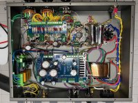
I started by taking stock of all the components, measured every resistor and capacitors to make sure the values were within range. Once this activity was completed, I knew I was ready to start the build. I followed the same sequence of assembly defined in the build guide. First, the power supply board received the resistors, the diodes, the capacitors, and the terminal blocks, followed by the input selector and the turnover select board.

In my next step, I fixed the transformer, the fuse casing, the switches, the pilot lamp, and the potentiometer. The kit came with a 2 prong IEC male and I replaced it with a 3 prong Furutech IEC Male Inlet which I soldered the ground pin of the IEC to the ground point of the chassis. As I had with me an extra grounding post I replaced the one from the stock. Next, I fixed the lug plates, the tube sockets, and the power supply board and started with the point-to-point wiring, carefully cutting the lengths and making sure it's nicely organized. The stock RCA female jacks were somewhat fragile, so I decide to replace them with KLEI Perfect Harmony RCA Female Jacks. The input selector board followed next.
Soldering of the wires and resistors was a very delicate activity keeping in mind the color legend (blue for firm and orange for partial soldering). I remeasured the resistors, capacitors cut them to proper lengths before attaching them to the lug plates. Believe me, this is a patience job, take your time, check and double-check to assure that you are fixing at the right position. Make sure the legs of the capacitors, resistors are not shorted with other components. A simple mistake would be a real pain to troubleshoot and refix. The final piece was to fix the turnover select board. I was excited that at last after 5 days the kit was complete.

Testing: I popped in the solid-state rectifier (V4) with some old Shuguang 12AX7 tubes (V1, V2) and Mullard 12AU7 (V3) and started measuring the voltage. I was thrilled that my voltage measurement was within range for the V1, V2, however, my joy was short-lived when I tested the V3 cathode terminal I was getting an abnormal voltage measure in the 256V range when the baseline is about 135V. All other voltages (Heater, MC) were within range. I knew at this stage that something was wrong, so I immediately send Victor my readings and within minutes I get a response to check the wiring in the area. As I was already tired and it was a late evening I wrapped up and retired for the night. The next day I started troubleshooting by checking each and every component and solder points meticulously and within hours I was able to pinpoint the issue. Surprisingly the issue was with a black cable that did not show continuity, desoldering the cable and installing another one solved the issue. All measurements were within ranges.

Now the fun part: I replaced the test tubes with Telefunken NOS 12AX7 (V1, V2) and Telefunken NOS 12AT7 (V3) along with the rectifier tube PSVANE WE 274B. Connected the power, put on an LP, set the switches on the phono stage, and pumped up the volume. Immediately I could feel the day and night difference compared to my existing phono stage (ANK L3 phono stage). The soundstage got bigger with tighter bass, amazing 3D imaging, the instrument separation and the details in the music was something I had never felt or heard before. I listened continuously for over 4 hours I was completely immersed in the music giving me goosebumps as I played LP’s after LP’s.

I can never thank Victor enough for the joy this kit has given me. My Precious Jazz collection has come to life. Thank you Victor once again.

Pictures of my build attached

Attachments

  • 2.jpeg
    2.jpeg
    272.8 KB · Views: 435
  • 4.jpeg
    4.jpeg
    314.8 KB · Views: 434
  • 5.jpeg
    5.jpeg
    321.1 KB · Views: 401
  • 6.jpeg
    6.jpeg
    255.8 KB · Views: 421
  • 11.jpeg
    11.jpeg
    344.4 KB · Views: 443
  • 14.jpeg
    14.jpeg
    458 KB · Views: 329
  • 15.jpeg
    15.jpeg
    285.2 KB · Views: 331
  • 16.jpeg
    16.jpeg
    327.2 KB · Views: 287
  • 18.jpeg
    18.jpeg
    305.9 KB · Views: 324
  • 19.jpeg
    19.jpeg
    96 KB · Views: 311

BA-3 FE Question

I have a BA-3 FE and I do like the sound. Perusing literature about it, I came across the Audio Society of Minnesota (ASM) article about the BA-3 as a preamp here Audio Society of Minnesota - Pass BA-3 Preamplifier

In the article, I read the following

We cut two traces to eliminate ground loop paths on the boards and added a lead to terminate at our chassis star ground. This is not the fault of the design, but these alterations are suggested for use in a single ended application.

I do not have a hum using the preamp driving my M2X, F4, Dynaco, and AKSA amps. I have a little hum when I use my 2A3 and 300B amps. I had been examining the board but I got nothing. I would like to learn which traces on the BA-3 board the article is referring to. Anyone can point me to which traces are those in the board?
Thanks for your help!

Comprehensive resource for comparing DIY speaker kits

I have attempted to create that resource. I have created a database and am including data points from the many popular designs from the many known designer and retailer

Favorite links/resources - E-Zees Crossovers


This spreadsheet is sortable and searchable by any of its columns. It will allow any viewer to compare from amongst all of the databased speaker designs, in one location. You will be able to
-search for kits using a specific brand or model of woofer/tweeter
-sort by speaker size or cabinet size
-sort by price of the bare speakers
-filter between fully published designs and those that require purchase of kit or plans from the designer.

Any data column can be sorted or searched. Are there other data columns I should add?

Currently I plan to host the searchable database on the homepage at ezeescrossovers.com. but it could be moved later once fully developed. If the above image isn't large enough to easily read, you can go straight to that site to see the same preview.

What I'm asking for here is some feedback and recommendations. Looking at that spreadsheet are there other data fields that are critical for this type of compilation? Is this even a resource that anyone else might feel is beneficial? I'd be grateful for some discussion. From my own limited perspective, I've spent countless hours bouncing back and forth from numerous web resources, searching potential speaker models for retail cost, looking at cabinet dimensions, and am hoping that a labor contribution to compile that all into one place might be appreciated.

Please be understanding that this is still under development and the web page itself is also under development. My hope is for assistance in final modification before the searchable database is finalized and published. You will see that the current tabs have designs separated by publicly published designs, unpublished designs purchasable only from the designer, with a third tab for some of the one-off designs which are published but not belonging to major designer or retailer.

Open to your thoughts.

Replacing caps in Threshold S/200

I have a Threshold S/200 amplifier. I don't have any problems with it but since it is 20 years old I'm thinking about replacing the PS capacitors.

The original capacitors are Mallory 15,000 uF, 80V. I found following capacitors in Mallory catalog that fit size-wise and have similar specs:

Code:
Cap (uF) ESR     Ripple   Catalog#       Voltage
17,000   0.033    8.8     CGS173U075W4C   75V
25,000   0.024   11.7     CGS253U075W5L   75V
15,000   0.043    8.6     CGS153U100W5L  100V
30,000   0.011   15.2     CGS303U100W4C  100V

Would any of these work? Should I consider any other brands?

While I'm at it, are there other parts that would be worth replacing? I read somewhere about updating rectifier diod in Threshold amps.

Thanks,
Adam

For the first time, I find myself more interested in amps than speakers.

Don't get me wrong, bad speakers are bad sound no matter what - and I still have a hole I am trying to fill (thinking something like a Zu Audio Dirty Weekend might do it...something a little more 'blank canvas'). However, since getting and playing with tube amps, an ACA build, I am finding myself thinking more about amps and less about speakers.

One direction of thought is the engineering on speakers (anything in the last 20, especially 10 years) from any repeatable brand, be it $100 or $100,000 a pair is just so good compared to the past, and with it, the quality and tolerance of parts (even cheap parts can sound wonderful when used properly).

Another direction of thought is decades ago when I was getting into the hobby, I heard about (I think) the British school of audio, which would mean a $300 pair of bookshelf speakers (from a quality firm, their entry level 2-way model) with a much more expensive integrated amp (maybe something closer to $1,000). This is opposed to the US school of thought which would be getting a great pair of speakers but not as good of an amp.

Anyway, the point being you obviously want good speakers and a good amp...but a bad amp will make good speakers sound bad...but a good amp will help bring out the best in a 'less-good' pair of speakers.

I'm not trying to convince you one way or the other, but after getting into this hobby as a kid, being broke, not being able to afford anything, over the years as I have been able to build up a nice system, afford better gear, I am finding myself researching and looking more at amps and less at speakers as the next step.

Just me, or others feel the same? Or are there other components (preamps, DACs, sources, cables, tweaks, etc.) you find yourself drawn to? For the sake of argument...maybe not touch on turntables, because that is a whole other can of worms (but still feel free to talk about those if you want!)

Advices for wires/parts for "boxing" an Amp

Hi,


Time to go from the lab bench to a nice box for my amp. This is a PCB base, with screw terminql blocks for power and speakers connections. Amp is 2x170W class D, Power voltage is 36V. I consider Speakon connectors as application is active speakers.


Boxing amps is an exercice that I'm pretty bad at, and would like to do better this time. Opportunity to learn !


Could you help me define the adequate wire gauge for power and speaker connection ?


Is some type of wire/insulation adviced (something not too exotic or difficult to find) ?


Are there some parts to consider for the Power cord connection ?


Are some accessories / tools helpful for boxing such amps ?


All advice welcomed,


Best regards,


JMF

Light Bulb Tester

Rangefinder writes that "Dim Bulb Tester" is more historically accurate. see post #38

A "Light Bulb Tester" is often suggested when testing a new or modified circuit. But it often takes much searching to find the tester. So below is a schematic and photos. I built the tester out of spare parts. I'll let others clarify using the tester.

Attachments

  • Tester1sm.JPG
    Tester1sm.JPG
    74.8 KB · Views: 4,263
  • TesterSchematic.jpg
    TesterSchematic.jpg
    43.2 KB · Views: 4,189
  • Tester2sm.JPG
    Tester2sm.JPG
    83.1 KB · Views: 4,215

Unclear section in WM8471 implementation datasheet

Hello diyaudio forum!


I'm in the process of planning and designing a DAC based on the WM8471, and there was a section i need a bit of help understanding, it's what looks like an unused/missing pins on the highlighted sections? it is rather unclear so if anyone with a bit of experience could help that would be amazing


WM8471 buffering section - Album on Imgur

Need advice on grounding strategy for a modular DAC

Hi,

As stated, I need advice on grounding strategy for a modular DAC project I'm working on. Let me explain.

Say we have a DAC board, a closely connected I/V board, a power supply board, a digital inputs board and a uController board in a metal enclosure. What would be the best way of connecting those components ground and noise wise?

I was thinking of providing separate ground wires for each of the modules at the power entry point of said modules to a common "star ground" and from there to the power entry/filter module's ground connector. Of course the enclosure would be grounded too. Matter of safety as I have red.

Any thoughts and help would be appreciated.

Best regards, Kovaxant

Can some one explain me this amp?

Hi, I stumbled acros this amp and I like to understand it.
I do not have it on the nbench any more so I can't give more details as given now.
It's a commercial design and I do not wish to disclose the manufacturer.

Here is a link:
http://docs.google.com/Present?docid=ddmq8v3q_8cdhv7fcr&invite=4dc5vw
But if you like mail me and I send you a good copy in pdf format.

1. If you look at the PSU, Where is the ground?
Are Q12 and Q15 setup to create a virtual ground?
2. Q14 and Q17 must be the power stage and Q5, Q18 the drivers.

At the moment I received the amp.
PSU part:
fuse F2 was gone.
R26, R73 of the -15V burned.
AMP part:
R16, 17 and Q5 gone.

After replacing this is what I noticed:
D16 is not lit (LED is OK)
+15V is present at R44. +1.8 over D16.
+20.9V at J1 with no load connected.
0V with load.

Why is D16 not ON?
Voltage to low but why?
I checked the parts around D16 and they are all OK.
All other power supp;y voltages measured normal.


What else can be said about this design.

Powering two PSU from one Transformer

Hello,

Is it fine to power two PSU from same transformer(different voltages)[book=]%[/book]. Please see image.

Transformer is 1000VA ( Transformer secondary wires are 2.5 sq mm)
0-28-36
0-28-36
Diode - GBPC3506 - four

Need to run two different PSU from same transformer(different voltages)

Is it fine to to connect 0V wire to two diodes as show in Image. This is for F5T v2(Mono) and Aleph2 (Mono) fed from same transformer.

Thank you

Attachments

  • thumbnail_DSC_0079.jpg
    thumbnail_DSC_0079.jpg
    139.1 KB · Views: 361

NAD 3240PE Purchase Dangerous!

Have a look at this.I brought this unit and is in realy excellent condition.I havent checked it over yet, but it does turn on.
good job i always check things before i plug them in.

have a look at this,beggars belief realy how someone wasn't killed or injured😱

Attachments

  • IMG_20210604_114001.jpg
    IMG_20210604_114001.jpg
    188.1 KB · Views: 230
  • IMG_20210604_114134.jpg
    IMG_20210604_114134.jpg
    458.6 KB · Views: 228

Open Baffle Speakers by Irkiosan

Hey there, this is a dedicated thread on my open baffle speakers. The speakers are quite easy to build, easy to tweak or upgrade, and they are pretty decent especially for the cost.

In the following posts, I'll provide details on the speakers, so you can replicate them and/or discuss with me about how to improve the speakers.

Disclaimer: I'm a recreational speaker builder with no commercial intensions. The present speakers are considered by me as being in beta phase. They are definitely ready to rock and I'm listening exclusively on them for almost a half year now. I will provide my wishlist of improvements along the journey here.

Ah Tjoeb CD-4000 Marantz TUBE CD player Pcb

For sale original Tjoeb CD4000 pcb full functional. This pcb tube cd player boatrd you can put in Marantz cd4000 cd player if you have one at home and you have truly superb sounding tube cd player. I also will give bouth transformets to the buyer.I also have transport, becose this is fully funktional cd player but without enclosure. So if someone will put together low price tube cd player this is good start. For more info plese contact me. Price is 100eu plus shipping.

Attachments

  • IMG_20210528_163526.jpg
    IMG_20210528_163526.jpg
    821.4 KB · Views: 225
  • IMG_20210528_163534.jpg
    IMG_20210528_163534.jpg
    599.4 KB · Views: 227
  • IMG_20210528_163541.jpg
    IMG_20210528_163541.jpg
    783.6 KB · Views: 229

Some DAC questions

Hi,

I am trying to learn to read documentation of ES9038Q2M DAC, but I am having trouble with some stuff:

1) Where am I supposed to pass audio for example from USB to the chip?
2) How am I supposed to control volume and is setted volume supposed to be remember somewhere after DAC lose power?
3) I am confused about filters. Does ES9038Q2M have integrated filters and I need to somehow select which filter I want to use?
4) Am I right when thinking that I can use AGND_R + DACRB + DACR and AGND_L + DACL + DACLB for balanced output, for example for XLR connectors?
5) Exposed Pad can be connected to DGND route track just like that?
6) What are SW, FSYNC, HPSDb, GPIO1/GPIO2, DATA1/DATA2, DATA_CLK, XTAL, SCL, SDA?
7) What is the purpose of ADDR in case of DAC?

Sorry about a lot of questions, but I am new to all of this and I am trying to learn how DAC works, but for questions above I can't find any explanations online.

Thanks.

built-in electronics for active loudspeakers - a wish list

Recently, a thread about "what do you prefer about passive crossovers" got me thinking about active crossovers and active (powered) multi-way loudspeakers, and how this has to be more of less "cobbled together" using external parts. For example, if I want to make a 3- or 4-way active loudspeaker (and yes, I typically do that) I need two 4-way or a single 8-way active crossover, and that many amplifications channels as well. My wife is very opposed to a cable morass that tends to occur when all these components are external and not in a dedicated cabinet of some kind, so I have always wanted to build everything into the loudspeaker. This would leave a power cable, and line in or (even better) wireless audio bringing the audio signal to the speaker(s). Unfortunately I have just not found good, compact, multiway amplification and DSP or other active crossover units that can be built into the loudspeaker simply and easily. So this thread is my daydream about what these components would look like. I invite you to put down your thoughts about the form/format that these physical components might use.

As an example, let's say I want to build a 3-way loudspeaker in an box. If electronics were available in a half-rack 1U size format they could be very easily built into a recess of this size in the rear of the loudspeaker. Amplifiers would be 1 or 2 channels, and a 4-channel DSP unit would provide enough analog I/O to run everything. I can sort of put this together now, from some components that I own, but not without some issues. Half-rack amplifiers are available, for example the small class-D amps like the TPA325x series, or even class AB amps, for example the Parasound Zamp v3. The problem is that these will generate heat and that would have to be removed, probably using a fan to pull air in/through. It's not exactly ideal to have a fan in your loudspeaker!

Most components generate heat, of course amplifiers but even line-level ones. Why not place 25-40mm deep heat sinking on the front panel, taking up the entire panel itself? If the components are assembled in a stack similar to a PA rack, the heat sinks would line up to form a taller one. I/O lines that lead external to the loudspeaker could come out of a separate panel, or from the crossover unit. Internal connections for AC mains power and speaker wires would be made via terminals on the side opposite the heatsink, the "inside", where they can be out of sight.

I think that this kind of market is probably quite small, since it would be specific to DIYers only. It would make things relatively simple, however, and I think it would be much more versatile than plate amps. Who knows, maybe it would become popular. You know: "build it and they will come". The user could add as many channels as he/she wishes using additional amplifier or crossover modules. The small "stack at the back" would keep things tidy and would simplify construction.

So, what do you (dear reader) think about this idea? Are there any other concepts/ideas for built-in active loudspeaker components? If you are a manufacturer out there and listening, this is a thread you might want to follow. We could use your input as well.

FS: MiniDSP, DEQX, B&C, Radian, Yamamoto, more

Hi all,

Well, after 10 years of designing and building hifi, I have a bunch of stuff that I'd like to pass along to this amazing community at a fraction of what it cost me.

If you're curious, you can see my work here

I am selling a range of electronics and drivers, both new and used, which I will be listing here (along with photos, as it makes sense).

I'd love to know if there are any local DIYers who'd like to come to my workshop (100 miles north of NYC) and take away the majority of what I'm selling, so I don't have to ship it. I also have a lot of hifi gear that we can have fun listening to. I will also give you a bunch of stuff for free. 🙂

Please DM me if interested, or reply here.

Thank you!
Rob

Stuff for sale

DRIVERS
  • B&C 21" Woofers
  • many more to come from Radian, B&C, BMS, etc.

DIGITAL
  • MiniDSP 2x4HD kit (qty: 4), new in box, $100 ea.
  • DEQX HDP Express-II, barely used, $500 (retail is 6x this)
  • Empirical Audio Spoiler, barely used, $1k (retail was 6x this)

SOURCES
  • SOTA turntable with Graham Phantom tonearm
  • Cambridge Audio Azur 840C, free, pickup only
  • Luxman DZ-111, free, pickup only

ELECTRONICS
  • AKSA Soraya amp
  • AKSA Swift preamp
  • Django TVC
  • DIY Hifi Supply TVC
  • Yamamoto 845 tube amp
  • Yamamoto preamp

miniDSP filter design with REW

Hi guys, I have a question on using REW to design FIR filters for a miniDSP 2x4HD.

I know that you can do a measurement with REW, and use that to generate the FIR filter coefficients to make the resulting response flat. You can then download these coefficients to the miniDSP and activate the filter.

In my case I have a 'measurement' from another source, which I can export as a .csv/Excel file. Does anyone know if it is possible to import such a measurement file into REW and use that to generate the filter coefficients?

Jan

Modify HK CDP to output i2s and coax spdif?

I am hoping to tap into an i2s signal in my Harmon Kardon CDP. However, I am not sure how to extract it from a CXD1167 chip. There is a prior thread that mentions the CXD1167, but it does not indicate which pins provide the outputs. I do not think the “resister” clue mentioned in that thread helps me for the following reasons:
According to the Tech Manual for the CDP, the CXD1167 D.S.P. feeds a “serial” signal to a SM5871AN dac chip. The specifications state that the SM5871AN is a dual single bit converter. The schematic for the CDP shows 3 lines from the D.S.P. (pins 76 (DA14), 78 (DA16) and 80 (LRCK) going to the dac after each passes through a 470 Ohm resister. These lines attach to pins 9 (BCK1), 10 (DIN) and 8 (LRC1), respectively, of the dac. The data sheet for the dac describes pin 10 (DIN) as “serial data input.” The data sheet contains a description of the “Audio Data Input” as “The digital audio data is input as DIN in 2s complement, msb-first, 16 bit serial format.” The Tech Manual for the CDP states that “the signals are output as 16 bit digital signals from pins 76, 78, and 80 of [the D.S.P.] and fed to the D/A converter. In this case, EFM demodulation, error correction, and serial/parallel conversion are performed by the internal circuitry of [the D.S.P.].” I assume the “serial/parallel conversion” means that the data line is not i2s. Might there be a different pin on the D.S.P. that outputs data in parallel format? I have searched the web and cannot find any data sheets for the D.S.P. (apparently it is a SONY component). Is anyone familiar with this chip?

The CDP also has an optical out. I note that the optical device contains an 8.2K resister in parallel with a .022 uF capacitor in front of the transmitter. (The optical device appears to be an HK part as the parts list describes it only as “E/O PLT102, Converter, Digital Output”.) The optical device is connected to pins 27 (DOTX) and 73 (VDD) of the D.S.P. and ground. Does that suggest that those lines are SPDIF? If so, can I just tap in before the optical device and add a coax jack? Any suggestions would be greatly appreciated.

Cobalt 430 Amplifier by Orion Repair

Hi, I have this amp to repair.
It is a 4 channel Mosfet amplifier shorted causing the fuse to blow and a PCB track interrupted.

A few years ago my brother took him to a boy to have him repaired but he told him that the transistors are not found.

I would like to try to repair it, but I noticed that a couple of mosfets are missing on the power supply circuit, the ones next to the SMW60N06 and I don't know if the missing transistors are always SMW60N06 or they are different.
Does anyone have any advice for me ?

Attachments

  • 1.jpg
    1.jpg
    690.6 KB · Views: 156
  • 2.jpg
    2.jpg
    614.6 KB · Views: 138

Calculating "peak" SPL for this driver combination

I'm trying to figure out what the "peak" SPL capability of this combination of drivers is, in a sealed cabinet, the volume of which is optimised for the 12" (sub)woofer. The loudness capability of studio monitors is usually specified in terms of "peak" SPL @ 1m. The system will be tri-amplified with DSP... Hypex or equivalent.

h9_aZitSwdCf6OU3F-UlCtscOWn2jN8GaMfhzV5p4C585JbuOLd4nkSisY0OViGLs0EeZR3VEkhficXguy8SvmMSQO1FIETvTaDJ5k5aRRNevI_Bu2uhUIe3Kc8CV5sTHbeYITkD5A=w2400


The Satori TW29DN-B tweeter has a sensitivity of 96 dB (2.83 V / 1 m, 4 Ohm), can do 112 dB SPL @ 1m when fed with 80W. But this is per "IEC 268-5, high-pass Butterworth, 2600 Hz, 12 dB/oct". (For the sake of this situation, let us assume I have the said filter in place.)

64lMR7ywneTsNlsYHqwTTX2Q2ZQwQA-WawwWbZEBc6lID3Jki0GWWPe3o0X5y-Vk2XyBh-H5PAa24N39Vh2EzTvhf4T5i_eZqEr3B5GlpUujQGGaxWRTBqaCETOmJJw8dGLxZx6qHQ=w2400


The Faital Pro 6RS140 has a sensitivity of 93 dB (1W / 1m) and can handle 200W (2 Hours Test According to AES 2-1984 Rev. 2003) and 400W at "maximum power". ("Maximum power is defined as 3dB greater than nominal power.") This speaker will comfortably do 112 dB SPL when crossed over above 200 Hz, so it doesn't worry me.

The SB34NRX75-6 has a sensitivity of 90 dB (2.83V / 1m) and a "rated power handling of 200W. (IEC 268-5, T/S parameters measured on drive units that are broken in.) I am able to simulate a response of 106 dB SPL @ 1m with -3 dB point at ~32 Hz, before hitting x-max.

G1fOb5ehYqSt_h39rmXFurfIH63a1UBucsmfhL_XzmabHF66RIlrtm6SGlvwQ2biETWsIe9FRhKVtBYTD9l0QEtaJBtUNImr7lkdpr_2lmrm-rwjXBmENAQ_VF_HiN0y_Vq64zBT9w=w2400


The SB Acoustics 12" woofer can deliver 106 dB SPL and the tweeter can do 112 dB SPL, but they comply with 'IEC 268-5' test standards, while the Faital mid-woofer complies with 'AES 2-1984 Rev. 2003'. As I said, the Faital is far too robust, so I'll ignore it for now.

I'm trying to figure out what IEC 268-5 means in this context. According to Wikipedia:

1ds074F9FcZ1RQ7x176iWphLUtvxX3b5s_1YL6u2G7M4oGkUEsZPoVqqgJysPoETVyw9XVsnnuHL3v7hS2obYGpJB1OiKCmx_rf1xAEGpdgbc7l3B0-B1PzW5xmWxDJW7jIOIK4eYQ=w2400


Now, by doubling the power to the 12" driver, I'm able to get a 3 dB boost in SPL, but the excursion goes to about 15mm... Xmax is 11mm and XLim (I think) is 17mm for this driver.

Two questions:

1) Looking at the 12" driver in isolation, is it fair to say that that it's "Peak SPL" is 109 dB @ 1m, while continuous SPL is 106 dB? (Excursion past 106 dB is > XMax but < Xlim).

2) What about the summing of the drivers? If the (sub)woofer and mid-woofer can each put out 106 dB continuous and 109 dB peaks, they should be able to put out 109 dB continuous and 112 dB peaks together...?

Thanks in advance,

Hitachi 2SJ217 / 2SK1297 - are these lateral FETs?

Found these in an old Sony car amplifier. They are only good for 60 V and were in fact run from +/- 18.5 V rails. The data sheet does not even recommend them for use in audio amps: "Suitable for motor drive, DC-DC converter, power switch and solenoid drive".

Transconductance and on resistance are pretty low, so are these lateral or vertical FETs?

upside-down circuit in push-pull

Can someone show me how to wire a push-pull version of the "upside-down" circuit (NOT a cathode follower) in figure-3.17B? It would be easy if the input transformer has split secondaries but what if you don't and not even a center tap? Is there a way to wire it in push-pull fashion and will it involve using two coupling caps connected to the cathodes or grids? I saw several single-ended designs and only one PP design that needs an input transformer with split secondaries.

I am not building an amplifier. I just want to understand it intellectually or how to apply or reconfigure it from SE to PP.

bild41-e1429877775777.jpg


upside-down-explain.jpg


199338d1291412002-jc-morrison-circuits-4cx250-gif

Help chosing second hand tube amp for 95db speakers

Hi all,

Recently i started my very own first project based on Phi by Klang und Ton design. Thread link > Help chosing high SPL drivers for 3way classic loudspeaker
Nominal sensitivity 95db @1w/1m
Xmax for speakers is 20w @115db, so we can conclude they are pretty sensitive 🙂

phi.jpg


Now i want some sweet single ended class A amp, and choice is boiling down to couple second hand projects and one solid state.

1.
Single Ended 2x 6P6S Russian Tetrodes 2x 3.6w paired with preamp 1x ECC 82 (Tungsram or Siemens, choice will be mine). Price is 100e which is sweet deal.

116857423_60abc8168fa771-78869811162186987585956.jpg116857423_60abc81691e2a1-18661813162187019856946.jpg116857423_60abc81693c888-95343091162187034522249.jpg116857423_60abc816957e38-98755165162187055666716.jpg

2.
Single Ended 2x 6080 triodes, 2x 10w. From the looks of it, it doesnt have a preamp integrated ? Price is 199e.


115651019_60912dac5e6803-68043887desktop-116.JPG115651019_60912dac6087c1-71971328desktop-117.JPG115651019_60912dac5cd100-28356081desktop-115.JPG115651019_60912dac5a3876-63467107desktop-114.JPG115651019_609ffad5b46a73-54598364IMG_20210515_15.jpg115651019_609ffad5afeaa3-60088724IMG_20210515_15.jpg

using a darlington for EF driver?

Use of integrated darlington transistors (i.e. driver and output transistor on one die) for the output stage is frownded upon because:
- most integrated darlingtons fail to impress regarding bandwidth and beta linearity when compared to the pairing of a first rate power transistor and a first rate driver (if there are exceptions, I am not aware of them)
- one is robbed of the possibility to use a shared emitter resistor in the driver stage which speed up the turn-off of the output transistors

We also know that a triple EF (aka triple darlington) has lowest distortion because it loads the VAS less and has sufficient current gain throughout the operating regime.

So how about using an integrated darlington in TO126 or TO220 case for the driver stage, thus making a triple EF? I don't remember ever seeing an example. Are there obvious downsides? Of course, there cannot be a shared emitter resistor for the predrivers now, but then the drivers carry less current than the output devices and are hopefully faster.

Dust Cap Types: Which to choose?

Hello...

Wasn't sure where to post this, since it would seem to apply regardless...
But in my case it will be a 3-way system, and for a (non standard) WOOFER re-cone.

Hoping experienced/knowledgeable re-coner types will chime in!

So... Dust-Caps....
Solid, Vented, Mesh, Heavy/light, Large/small... Plastic (poly) Paper etc...
(and anything else I haven't thought of)

What are their "properties" in terms of what characteristics do they impart?
What other factors are to be considered in choosing which type??

TIA!

Greg
Projects by fanatics, for fanatics
Get answers and advice for everyone wanting to learn the art of audio.
Join the Community
507,400
Members
7,868,867
Messages

Filter

Forum Statistics

Threads
405,320
Messages
7,868,867
Members
507,400
Latest member
Marcelbcm