Restore Hallicrafters S-85 Shortwave Radio

I have a Hallicrafters S-85 shortwave radio that I would like to restore. It's a radio I grew up with so the restoration is more for personal reasons rather than value or a collection. Are there resources out there for parts and service? An internet search turns up some places that deal with old radios but since it's not something I have dealt with before I would value some recomendations.

Need owners manual for AES SE-1 300b power amp

Greetings all. Might anyone have a copy of the owners manual for the Audio Electronic Supply SE-1 300b power amp? I have not been able to track one down and Cary has not yet responded to my email to them.

Alternatively, if anyone else out there owns one of these amps please reply to this thread - I have a few simple questions I'd really like some help with.

Best regards,

Markus

adding preamp outputs to Sanyo Plus 55

I am thinking of adding preouts to my Sanyo Plus 55 receiver. I used to be a licensed repair tech, so I can read a schematic and build from one.

I am not an engineer and would like someone to look at this.

I identified, on the schematic, what I believe are the outputs on the pre section and the inputs on the amp section. Circled in red.

I think this is the input to the amp section:
attachment.php

I think this is the output from the preamp section:
attachment.php

Rebuilding 1972 Marantz Receiver

QUESTION:

As I'm going though this receiver, I want to replace
all the old 51 year old ceramic caps with either new
films, or Micas, or new C0Gs.

I haven't done anything with the AM or FM boards, yet
and probably don't want to replace those tuning ceramics.

However for the other boards, like tone amp, etc, is there a
reason to keep the old ceramics in there? They get noisy with age,
they become micophonic etc. I assume even the 51 year old NP0s
on the phono board get that way also.

I'm upgrading Transistors, diodes (and caps) as I come across them
board by board for new modern replacements.

This receiver is for my little girl who loves music.

Cheers,

Billie Eilish Bad Guy stress-test for turntables?

Hi all,
this is for me more out of curiosity than anything else, as I don’t really see it as a “problem”.

You might be familiar with the first song on Billie Eilish last album and its extreme bass. It sounds great to me from the vinyl but it really feels that it is driving the cartridge to its limit. The thing is that in my system, while sounding good, it generates some clicks, like if the record had a scratch, but it isn’t that because they are not regular and not always at the same time if you play the track twice.

I am really curious to know what is causing that. Is the stylus generating too much signal or something like that? Has anyone observed something similar in this or any other song with lots of bass?

I use a Pro-Ject X1 with a Pick it S2 MM cartridge (which I believe is an Ortofon red) with a Trigon Vanguard II/Volcano III phono stage

Matsushita AN136B low noise high gain audio preamp (vintage)

Some NOS items came up on a local auction site, I wasn't able to find a datasheet so I have no idea if they'd be any good for a phono preamp or similar.

I understand they're equivalent to NTE1053 but the specs I could find on that IC were also scant.

They come in a round can with 10 pins.

If anyone can shed light or share any information, I'd be interested. TIA.

Problem using OPA134 model in LTSpice

Hi to all Spice experts.

I'm a relative novice and trying to work out how to use audio opamps that are not in the standard distribution (e.g. 5532/4, 071/2, OPA134). My version of LTSpice on Mac OSX is 17.0.33 which I believe is current.

I have found a model for OPA134 on the net, I believe from the manufacturers site. This is attached. I have loaded the .lib file and created a symbol from the related .asy file, so I can now add the opamp from the [autogenerated] folder in the F2 dialogue box.

Everything OK until I run and then I get this error message:

Unknown subcircuit called in: xu1 0 n001 v+ v- n007 opa134​

I'm assuming this is an issue within the model file? Any advice welcome.

M

Attachments

3 way crossover design advices

hello all
I want to build sealed speaker with this items
1. Dayton Audio DS315-8 12" Designer
2. Goldwood GM-65/8 Sealed Back 5-1/4" Midrange 8 Ohm
3. HiVi Q1R 1-1/8" Textile Dome Tweeter
I have already have them .

The box is gone be 37X30X70 cm and will get it soon .

The question is about the crossover .
The woofer has a peek on 1KHZ-2KHZ and have to terminate it and crossed about 600-700HZ .

what else we have to take care of ?

Damping material for Dallas 2 BLH

I'm embarking on building Dallas 2 BLHs, but the tricky part is that I'm in Azerbaijan where audio shops don't really exist - so everything has to be imported, usually from USA or perhaps UK and ideally from as few places as possible. I can't get anything in-country except plywood.

I'm looking for advice on what sound damping material to buy, how thick, how long and where to place it. I'm hoping to buy from Madisound because they have other bits and pieces - terminals and t-nuts/bolts etc.

As I understand, I need to line the cavity behind the FE206EN, plus around the two bends in the horn.

In the cavity, do I need to line with felt or fill with wadding, or both?

Wherever I need to line, Madisound has a choice of 1/4" wool felt or 1/8" felt

For wadding there's a choice of three, wool, polyester and "Acousta-Stuf"

Any advice on choices (or alternatives) gratefully received. I'm very conscious that once I close the box I can't do anything about the bends so I only really get one shot at importing the right materials.

Also...when filling the voids in the boxes with sand, I've seen a few comments about sealing it neatly, I was wondering whether candle wax might to the trick - melt, pour in the top 1cm or so, smooth off. Or I could use cement, but it'll be wet until it cures.

Thanks

new 300b Surface Super Scaler build

I just received a contract to build a 300b stereo amp. Actual going to build two, keeping the second one for myself, and drive it from my existing desktop amp. My client intending to drive it from her Sansui 7070db stereo receiver.
I was never going to do a 300b build, but she buys all the parts for me.

Fine, I show others how I do the filaments......

Attachments

  • LV Supply.jpg
    LV Supply.jpg
    20.6 KB · Views: 211

The humble Polyswitch

Hello, I see lots of PA designs here that use glass fuses on the rails and some that have elaborate SSR based protection on the output. Don't think I've seen one that uses Polyswitch's? Is there a reason they are not used more widely?
Perceived sound quality? Reliability? Trip current accuracy?
Back in the day when I was more fanatical about SQ, fuses and relays were a no no so cant imagine the poly would be worse?

Hi-end 845 with only two stage

yesterday evening I have started some measurement about 6HV5A used like 845 driver.

The schematic was very simple: inductance on anode, Rk = 100ohm, Ck = 470uF, Rg = 75Kohm and output capacitor 2.2uF on 33 or 100Kohm load.

With medium voltage operation (about 600V) these tubes give low sperformances because distortion is high 1.1% at 25Vrms.

The good result are obtain using 980V and 100ohm on catode to keep the power nead the 30w (35w is the maximun allowed), bias about 30mA.

With these value I have got the good 1% at 120Vrms on 33Kohm load.

The freq. response is limited to 50Hz(-3db) with 20H but it will be 10Hz(-3db) using 100H 50mA Sowter 8982.

The voltage amplification is 120/0.7=155x.

audiodesign has attached this image:
Click the thumbnail to see the original image.

Attachments

  • plot_980v_100ohm_470uf_20h_load_100k_ver2a.jpg
    plot_980v_100ohm_470uf_20h_load_100k_ver2a.jpg
    92.3 KB · Views: 6,335

Mullard 5-20 KT88 PP blocks!

I'm deparately seeking comment from you experts so this project can begin NOW! After alot of research, and reading, and input here. I have decided once and for all on topology, and output power.

I should first state that i'm quite green, but have decent build skills, and some general idea how tube amps work. I am not able to design, and trouble shooting without hand holding would be very limited. I have one ST70 New build under my belt.

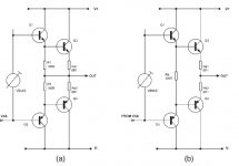
I have decided on what Eli had suggested. A modified mullard 5-20 LTP type driver with some type of CCS in the tail. Outputs will be 2 KT88's run Ultralinear, and output goal is about 60W. Builds will be constucted on custom mono block chassis. All parts will be new, and of good to better quality. The build should be as simple as possible while still offering quality equal you better than commercial offerings of the same class. Cost is not a concern within reason.

I'm looking at 3 options to get started, and would like the disscussion limited to those option. I'll just confuse myself otherwise.


Option 1

Was created by forum member Zafir 1983 by modifing an existing schematic with input from all the Gurus on this forum. IT meets all the requirement except complexity. I have no idea how to design a first class PS, or pick the transformers. A fully P2P project could be over my head. However, I know you guy's like the Schematic. Wavebourn said it was on of the best for PP he has ever seen! Another issue is that it has not been put on a scope and tested. Also there are no other proven builds for refference. This one sounds very risky for a newby to me Here it is.

404 Not Found
( Anyone willing to help with this one? that would mean a full PS schematic, and recommended Transformer model numbers!)


Option 2

would use a Mark III upgrade board from Diytube, and very loosely follow the rest of the MarkII schematic. . I used this build option with the ST 70, The results were great, and this may be more within my ability. Shannon has created a Modified 5-20 circuit that includes the CCS. The key here is I can use the Comlpete MarkII schematic as a great guide. Repro Trannies are availible, and the power supply could be upgrade, or replaced with a SDS upgrade board. Some here didn't like the driver tube choices (12ua7), but some limited options are availble (12BHt), and even some 6 volt options. This one is very doable for me.
Here's the schematic.

http://www.diytube.com/unidriver/poseidon.pdf


Option 3 would be the same as option 2 except using the Triode Mark III replacement board. This appears to also be a 5-20 type driver? I don't see where a CCS is used on this one but it does seem to have move driver tube options. I can't find a schematic, but here's the info.

Driver Boards for Dynaco Mark II and Mark III


Any comments keeping in mind that my design / electronic skills are limited?

EAW CAZ2500 and CAZ1400 repair (SOLVED)

Hi, I'm posting this just for future reference, as I found no service information on these amplifiers online whatsoever.

The internals of the EAW CAZ-series are nearly identical to the Alto Mac 2.2, Mac 2.3 and Mac 2.4 amplifiers. Alto Macro 830, 1400 and 2400 are also very similar. I figured this out by googling the part numbers on the PCBs.

Repair manuals and schematics for the Alto amplifiers are easily found if you look for them. This brings me to another issue. The alignment procedure in the service manual for the macro series is missing, however in the manual for the mac series the alinment and test section is present. I believe the procedure used in the mac series repair manual can be used also for the macro series amplifiers.


EDIT: just as a follow up:
on the CAZ 1400 (similar to mac 2.2 or 2.3) all I did was replace output transistors. i spent a day matching up quads, then put them in.

On the CAZ 2500 (MAC 2.4) the problem was more tricky to track down. One of the input capacitors was bulging and 2 fuses were burnt. After going down the wrong path serveral times I realized that there was a bad connection on top of the board between -55V from the rectifier board and its corresponding filter capacitor on the amplifier board. This resulted in reverse voltage across capacitor C222 which caused it to short and spill its electrolyte. Connection was broken between E215 and C222 negative terminal as the leg of the capacitor had failed to make proper contact with the pad. Installing the new part I could only make intermittent contact so I had to add a wire underneath the board to properly solve this. I had already replaced all four filter capacitors, but I'm guessing C222 (possibly C223 as well) was the only one being damaged by this. Good thing I powered this thing up with a light bulb in series with the power connector effectively reducing the line voltage and all voltages within - or I would likely have blown up the new capacitor as well.

shelving bass boost circuit

Hi, I am trying to make a bass boost, based on the Big Muff tone stack.

It is smth like a Tilt control - boost low/ attenuate highs, flat, boost high/ attenuate low, around a corner frequency.

I want to use the bass boost setting, smth like low shelving filter.
But, all I can do is smth like high shelving.
The potentiometer in both end positions acts like a high boost, not like tilt.
I cannot make it boost the lows and attenuate the highs (exactly the opposite).

Is it possible to make it work in this transistor configuration?
- common collector (if not wrong)
- frequency dependent gain, via the tone stack in the emitter chain.

I did not want to use the tone stack in passive mode:
- buffer > tone stack > recovery gain stage.

The best would be one transistor (extremely low consumption, battery powered), gain 0 for the highs, gain ~6 db for the low shelf.

Regards, Emil.

Attachments

  • 10k_big_muff.PNG
    10k_big_muff.PNG
    33.6 KB · Views: 431
  • b_blend_06_sim_01.PNG
    b_blend_06_sim_01.PNG
    96.7 KB · Views: 421

ESS DAC chips register readout - how?

Hi folks,

today I built and tested a MCP2221A USB->I2C interface and a I2C isolator with optocouplers. To actually test the function I used one of iancanada's ES9038Q2M boards which was lying around.

We're currently in the process of developing a DAC board with this chip and the corresponding PC controller software... Will finally become a multi channel solution.

So right before I had to stop my experiments today because of time constraints (we have to be home by 10 pm right now in germany) I got the register write working. Had to wrap my head around the I2C adressing and needed an oscilloscope to find out that i had to rightshift the address 0x90 by 1 bit to actually make the DAC chip send the ACK on the I2C data line. Weird conventions but hey, who cares if it works 🙂

What I could not determine from the datasheet is how register read access works. Do I need to send one byte with the register number and then read one byte to get the register contents back?

I would greatly appreciate info on this topic, be it in text form or any kind of working/tested code, don't care which programming language.

FS: Audax HT210K2 8 in. woofer pair

Audax HT210K2

I have been using 1 for about 6 months and the other one is brand new (~5min) but mounted.
$50 + shipping (fees/insurance included)

Specs
Ohm rating is 4 ohms
Power is 100 watts in a cabinet
SPL is 89db 1000 Hz. at 1 watt at one meter
Fs is 63 Hz
Re is 3.00 ohms DC
Qms = 9.39
Qes = 0.60
Qts = 0.57
L1 = 0.67 mH
L2 = 1.00 mH
Vas (Sd) = 11.33 liters
Cms = 157 uM/Newton
Bl = 8.98 Tesla-M
Freq. Response 30 Hz. to 3,500 Hz.

An externally hosted image should be here but it was not working when we last tested it.

An externally hosted image should be here but it was not working when we last tested it.

An externally hosted image should be here but it was not working when we last tested it.

12v Party Bike

Hi folks

I'm looking to combine my two passions (audio and bike building) and would really appreciate some assistance. I've recently built my own bakefits style cargo bike, and now I would like to kit it out with a 12v sound system so I can take it to friends houses/the park and crank some tunes (both on the way and while we are at our destination).

I have some 12v components from an old Car sound system that I salvaged and would like to put to use. Namely a 12" pioneer car sub (TS-W308D4), some JL audio 6.5's (with tweeters), all run off a Sony Xplod 4 channel amp (XM-GTR4A). It is unlikely I will be able to find a suitable deep cycle battery where I am living (Laos) so will likely have to use a 2nd hand car battery. I already have a battery charging unit that I will include in the install so I can plug it into wall mains where possible (house parties).

My current thinking is that a simple slot ported sub tuned to the 35hz region would be a sufficient cornerstone for this application. That being said I have no experience with this style of sub!

Here are the TS parameters for the 12" pioneer


Revc- dual 1.5
Levc- 2.18 (4ohm)
0.65 (1ohm)
Fs- 33.7
Qms- 14.11
QES- 0.5
QTS- 0.45
Vas- 36.16
Rms 2.773
Mms- 184.95g
Cms- 1.2x10 (to the power of minus 4)
Diam- 242mm
Bl-16.07 (4ohm)
8.04 (1ohm)
xmax- 8.7mm

I have had a go at modelling something in Horn Response and came up with a 58l box with an Ap of 35 and Lpt of 10. That gives the box a 35hz corner and about 92db sensitivity. The thing i'm not sure about is if I am going to have issues with port velocity/chuffing. I was using an online tutorial on Home theatre shack and there was no mention of how to calculate/view this.


Also, are there any dimensional minimums i should be considering when designing the port? Ie would a 35cm tall, 1 cm wide slot port, perform in the same way as a 10cm tall, 3.5cm square port?


Would be great to have some experienced folks along for the ride on this build!


Cheers,


Mark

Attachments

  • cargo bike.jpeg
    cargo bike.jpeg
    220.1 KB · Views: 314
  • Pioneer 12.PNG
    Pioneer 12.PNG
    21 KB · Views: 320

LME49810 - a new cousin for LM4702

Hi chip heads,

LME49810 is a new audio power amp driver chip which appears in National Semiconductor's latest Analog Product Guide (2Q2007), available at http://www.national.com/whatsnew/files/national_analog_product_selguide.pdf (88 pages, 1.7MB)

The product folder is at http://www.national.com/pf/LM/LME49810.html and the PDF data sheet (22 pages) can be downloaded from there.

Its been briefly mentioned in the LM4702 thread http://www.diyaudio.com/forums/showthread.php?s=&postid=1222529 but I thought a new thread should be started.

The LME49810 is a 'single' cousin of the 'dual' LM4702, although its output current is about ten times that of the LM4702 and new features have been added like soft clamping and dedicated bias pins for the Vbe multiplier. The power supply rails are up to +/- 100V, slew up to 50 V/uS.

My samples have just gone into 'shipped' status from Singapore, so the first prototype amp is not far away....

Source for Alps Alpine rotary band switch cables

Does anyone know a source for replacement band cables for the Alps rotary selector switches used in squillions of integrated amplifiers? They are commonly a blue lattice with a stainless steel band inside, though in the picture below they are black.

The band / strap / cable connects a rotary control to a PCB mounted slide switch, commonly used for input selection, etc.

1pcs-lot-Japanese-ALPS-cable-band-6-switch-handle-length-25MMF.jpg


T2KUHdXm8XXXXXXXXX_!!116528884.jpg

Altec 1570B Interest

I picked up an Altec 1570B last week. As much as I would love to mod this (and find another), I don't see it happening in the near future. So I thought I would put out some feelers.

It is very clean and unmolested. There is some dust and surface dirt, but inside the base the whole layout is clean, with no signs of overheating or failure. No one has messed about with it. Original caps, original everything.

I have not run any power into this yet, my variac is on loan, and I won't see it for a week or two.

So I am basically curious as to if anyone has any interest. I see a few on Ebyay but am not in any hurry to sell through them. I am in PA and would prefer meeting someone than shipping this 75 lb. beast.

Attachments

  • Altec1.jpeg
    Altec1.jpeg
    83.9 KB · Views: 244
  • Altec2.jpeg
    Altec2.jpeg
    162.8 KB · Views: 243
  • Altec3.jpeg
    Altec3.jpeg
    134.5 KB · Views: 242
  • Altec4.jpeg
    Altec4.jpeg
    103.6 KB · Views: 248
  • Altec5.jpeg
    Altec5.jpeg
    123.4 KB · Views: 236
  • Altec6.jpeg
    Altec6.jpeg
    111.7 KB · Views: 122
  • Altec7.jpeg
    Altec7.jpeg
    99.5 KB · Views: 106

Graphene and TexTreme Studio Monitors

I recently ran across these speakers and found their feature set and component technologies to be quite interesting, especially from a DIYaudio forum perspective.

https://exmachinasound.com/wp-content/uploads/2017/02/QUASAROneSheet.pdf

Graphene and TexTreme:
The coaxial midrange/tweeter is noteworthy. The midrange is a 6-1/2" TexTreme cone serving as the waveguide for the 1" Graphene tweeter. The company says the Graphene tweeter comes from OraSound and the TexTreme cone comes from Oxeon, but they worked with Seas to develop the driver. Seas seems to manufacture all their drivers.

Technology | ora-sound
TeXtreme

I must have missed seeing this Seas coax when it became available with their Graphene drivers.
Seas Excel 5" Graphene Cone Coax C16NX001/F (E0080-04/06)
I wonder if Seas is using this motor structure for the Ex Machina coax driver?

Ex Machina is using Hypex nCore amps to drive these active speakers.

They talk of developing their own filters and processing algorithms that run on a SHARC DSP. They must be implementing FIR filters since they are touting phase correction. AKM DACs are being used. I wonder if they are sourcing their DSP from Audiotec-Fischer, miniDSP or an entirely different outfit (both offer SHARC processors and AKM DACs)?

They also build their cabinets using Valchromat, which is the colored MDF material that Troels Gravesen uses on all of his most recent builds.

Apparently the speakers are built in Brooklyn, NY and are priced at $11,500 for a pair. Considering what goes into these speakers, that doesn't seem as obscenely priced as some studio monitors and definitely most audiophile high-end speakers.

I thought this was a very appealing collection of components that went into these speakers. I wonder how they sound?

Attachments

  • EXMACHINA-QUASAR-6.jpg
    EXMACHINA-QUASAR-6.jpg
    379.5 KB · Views: 475

  • Locked
6Э5П / 6E5P NOS, NIB, measured on The uTracer 3+ (in triode mode).

hi!

I have in stock excellent electron tubes 6Э5П / 6E5P.
All tubes NOS, NIB, the same data code (1978-79).
Additional, the each tubes was measured on The uTracer 3+ (in triode mode).
The results of meashurements (on 3 points) marks on each tube boxes.
Аll substandard items went to the trash.

400 psc in stock, 50 pcs in box, minimum order - 50 pcs (one box)
price 50$/box (i.e 1$ for 1 pc of 6Э5П / 6E5P)

weight of one box (50 pcs in box) - 1,590g

Best regards!

-------------------
Olexandr
Kharkiv, UKRAINE
skype: OAA-1974

Attachments

  • 6є5п.jpg
    6є5п.jpg
    330.6 KB · Views: 383
  • IMG_2871.jpg
    IMG_2871.jpg
    588 KB · Views: 380
  • IMG_2872.jpg
    IMG_2872.jpg
    954.7 KB · Views: 387
  • IMG_2876.jpg
    IMG_2876.jpg
    821.4 KB · Views: 367
  • IMG_2877.jpg
    IMG_2877.jpg
    752.9 KB · Views: 366
  • IMG_2876 -111.jpg
    IMG_2876 -111.jpg
    492.3 KB · Views: 184

  • Locked
FS: NOS, matched - ECC85, EC360, RE025XA, 6C33C-B

FS: NOS, matched RFT ECC85, EC360

For sale brand new NOS, tested, selected tubes:

1) ECC85 RFT East Germany, 28pcs, NOS, the same data codes (Dec 1972), matched quad = 25$/quad

2) EC360 RFT East Germany, 4pcs, NOS, the same data codes, matched quad = 120$/quad,


Best regards!


Olexandr
Kharkiv, UKRAINE

skype: OAA-1974

Attachments

  • ec360 -11111111.jpg
    ec360 -11111111.jpg
    151.8 KB · Views: 500
  • ec360 - 22222.jpg
    ec360 - 22222.jpg
    104.2 KB · Views: 505
  • ec360 -3333333.jpg
    ec360 -3333333.jpg
    142.1 KB · Views: 494
  • ecc85 - 11111.jpg
    ecc85 - 11111.jpg
    101.9 KB · Views: 493
  • ecc85 - 22222.jpg
    ecc85 - 22222.jpg
    100.4 KB · Views: 497
  • re025xa - 111111111.jpg
    re025xa - 111111111.jpg
    118.3 KB · Views: 135
  • re025xa - 33333333.jpg
    re025xa - 33333333.jpg
    122.5 KB · Views: 135
  • re025xa - 444444444.jpg
    re025xa - 444444444.jpg
    97.3 KB · Views: 122

Converting ADC EQ circuit to tubes

I am even less skilled at analyzing SS circuits than tubes so maybe you all can help me translate this basic idea to tubes.

The schematic fragment below is from the ADC Sound shaper II owner's manual that I got with my unit years ago. I would like to understand how to implement such a thing in tubes.

attachment.php


So let's see if I am interpreting this right. It looks to me like the input comes into TR102 for amplification. TR104 and TR106 appear to be some sort of LTP with output taken from the collector of TR104. The shaping network is connected across the inverting and non-inverting inputs of the LTP. I presume that this is set up as a FB network.

Am I close? Would this be duplicated by seting up a tube LTP like is done for PP amps with FB brought back to the LTP PI and connecting the network across the input and FB point?

Attachments

  • ADC_SSII_frag.png
    ADC_SSII_frag.png
    773.8 KB · Views: 205

Crc grounding question

For my preamp im feeding an lm317/337 regulator from a crc supply and using a star ground/ground fill for the pcb. Ive made the layout such way that i have the the choice of moving the return diodes to either the 1st c or the 2nd c of the crc supply. Its my understanding that the diodes should be where theres most amount of pulse. So should that be the 1st smoothing cap in my case or the 2nd one after the resistor? And where should i keep the return diodes near by?

6 Channel TPA3116 + DSP

Morning all!

Since my stalled project to sync several class D boards for bi-amping is at the mercy of international delivery I've turned my attention to another project.

It is a stereo tri-amped active DSP system (2 x 4" mid [8ohm]/ 1" tweeter [4ohm] satelites & 2 x Tang Band 6.5" [4ohm] subwoofers - sealed) and I think I have found the board that will do the trick for it:

AIYIMA TPA3116 Amplifier Audio Board 5.1 Channel Digital Power Amplifier Board 50W*4 100W*2 DIY 5.1 Home Theater DC12 24V-in Amplifier from Consumer Electronics on AliExpress - 11.11_Double 11_Singles' Day

attachment.php


It looks quite tidy, the output inductors look fairly chunky and similar to Wurth counterparts which might indicate they have a similar saturation point of around 6A (744750420100 | Wurth 10 μH +-20% Ferrite Power Inductor, 6.2A Idc, 15.5mΩ Rdc WE-FAMI | RS Components). I will be using the balanced in connections via some better quality coupling caps from 3 x Sure ADAU1701 DSP boards.


The subs would be run from the two PBTL chips whereas the mids and tweeters will have chip each to share.


What do you guys think of it? I have ordered it just to see what it's like for now.


As far as PSU goes I was looking at this but have been told this is overkill:

SANPU SMPS 24V 500W DC LED Switching Power Supply 20A Constant Voltage Single Output 220V 230V AC/DC Transformer Driver Indoor-in Switching Power Supply from Home Improvement on AliExpress - 11.11_Double 11_Singles' Day

But I would prefer something sold in Europe that has to conform to our safety regs even tho it is a little under-powered. Could I use bulk caps to get round this?

MEAN WELL LRS-350-24 Switching Power Supply SMPS 24V 14.6A 350W - Audiophonics


This is not a big budget build otherwise I would have looked at other boards but finding balanced ins and multi-channel is difficult to begin with!

🙂

Attachments

  • AIYIMA-TPA3116-Amplifier-Audio-Board-5-1-Channel-Digital-Power-Amplifier-Board-50W-4-100W-2.jpg
    AIYIMA-TPA3116-Amplifier-Audio-Board-5-1-Channel-Digital-Power-Amplifier-Board-50W-4-100W-2.jpg
    120 KB · Views: 5,807

Questions for a Bridged LM4780 build.

I have been interested in building a LM4780 stereo amp for quite some time now. I am looking to get over 100watts into 8 ohms.

I would like to use 2 of the audiosector boards, each in bridged configuration. I will be completing the build using 2 300VA 22v transformers along with 2 of the power supply boards.

I think I read somewhere that I would need to use these transformers for bridged mode to go from unbalanced to balanced since I don't have a source with balanced output.

EDCOR - WSM Series

but with this i do not know how to make the connections to the amplifier board with the 3 conductors of the balanced connector.

Any help is appreciated!

FS: Iron Pumpkin

Hi,

Here I have for sale one of the Zen Mod-s finest creation.
Very versatile preamp with no sound of its own.
Built to out-last most of it's owners 😀

All rca connectors are CMC, box is modushop slim 3U/280.
Custom made oversized volume knobs.
AC transformers are high quality made by trafomatic.
Price would be 900€ + transport/PayPal expenses.

Attachments

  • IMG_20210130_182918.jpg
    IMG_20210130_182918.jpg
    980.7 KB · Views: 1,488
  • IMG_20210207_125713.jpg
    IMG_20210207_125713.jpg
    110.5 KB · Views: 1,450
  • IMG_20210131_090401.jpg
    IMG_20210131_090401.jpg
    989.8 KB · Views: 1,440
  • IMG_20210131_090325.jpg
    IMG_20210131_090325.jpg
    719.8 KB · Views: 1,414

LR8 low current/high voltage regulator with a ZENER?

I was looking at data sheets for the LR8 high voltage/low current regulator IC and came across one for the discontinued VB408. In that data sheet I found an interesting little circuit (attached).

Like an LM317, these regulator ICs set their output voltage with a voltage divider from the IC OUT pin to ground, with R1 from the OUT pin to the ADJ pin, R2 from the ADJ pin to ground.

This attached circuit, instead of using an R2, uses a zener string to set the output voltage, retaining R1. The value of R1 needs to be chosen to supply necessary current to the zener string, maybe 10mA. The LR8 only needs minimum 10uA from its OUT pin to its ADJ pin.

The data sheet says,

The output voltage can also be set by a zener diode put between the adjustment pin and ground (Figure 2). The biasing current of the zener is properly chosen by R1 resistor. The zener diode improves the ripple rejection and reduces the value of the worst case output voltage error. In this case the output voltage is given by

Vout = Vref+Vz

I'm sure this can be done with an LR8 too. A string of four 75V zeners and one 51V zener should get Vout = 350V.

The expected load on the LR8 would be 35V dropped across it (385V input, 350V out) at 7.5mA, so 263mW dissipation.

Stupid idea?
--

Attachments

  • HV Regulator with Zener Diode.png
    HV Regulator with Zener Diode.png
    9.3 KB · Views: 521

Does OPAMP offer gain?

Hi,

Sorry my ignorant question. Not very technical here.

I have a DSP that has a sensitivity of 0.9vRMS single ended. Right now I am using an amplifier that requieres 1.2vRMS for full power, so not a problem.

I will upgrade to an amplifier that needs balanced or SE input, but has a sensitivity on 2vRMS.

My idea is to use a converter or preamplifer between the DSP's output and the amplifier's input.

Do I need a SE to balanced converter like THIS which offer a 2x / 6dB gain.

Or I can get away with a preamp like THIS

I know this opamp are probably fake, but let's suppose they are the real deal (I can eventually buy some OPA1656 from Mouser).

This is a 16 channel DSP so I kind of need a "cheap" solution.

Thanks in advance

Audio Research SP-10 Clone HELP please

Hi,

First I would like to say that this preamp will surely sound really good since it already does even with the issue I'm having...

I built this preamp about 2 years ago since I wanted to familiarize myself with tubes. Had a couple hiccups and made everything work but a humming sound was there and I don't believe it was ground loop. I couldn't figure it out so I let it sit there collecting dust for a long time...

I recently started to go back on that SP-10 preamp when I had spare time at night. I've removed every AB resistors since they were old and non matching. Some of the values were really off... I've installed PRP resistors all over. The sound is better and the "shhhhhh" sound that was really heavy on one channel is gone. I still have some of it in equal strength on both channels but much lower. The noise floor is still not quite there. I was thinking it could be the tubes I used in the power supply so I'm ordering better ones. It uses 6L6 and 12AT7 in the PSU. The 6L6 that I have now is a EH and the 12AT7 is EH as well. The ones I'm getting are Tung-sol 6L6G (Big Bulb) and Mullard CV4024 for 12AT7. Don't know if this will help reduce the noise floor...

One thing that bothers me is a "hum" issue, maybe a ground loop but doubtful... There are two 0.47uF caps between the 6922 tubes. Whenever I put my hand near them 2"- 3" it starts humming much louder, touch them and it is really loud... I've tried different caps there (Solen, Dayton, Obbliggato...) but they all do the same thing. If I don't put my hand close to the caps, I do get a lower hum that goes almost away when I touch the signal input ground with my bare fingers while music is playing... Go figure... 😕

Now keep in mind that it is still on plywood for prototyping but I would appreciate your help on what to try next...

Here's the PSU schematics but I don't have the preamp's just the BOM...

SP-10 psu.jpg

Thanks
Do

Tektronix 120-086 transformer

Hello guys,
i'm not sure if tube section is the right place to start the thread about a Tektronix transformer i just bought for 40,00 €

Pic or it didn't happen ,right ? 🙂

The Tek part num. is 120-086 , the guy who sold me the thing told me it was salvaged from a 541 o-scope and service manual show that is true.

So i have all the voltages from the servie manual but no current ratings, except heater windings.

I could use the voltage drop on the series 10 ohm resistors stated on the service manual, but i think this monster is capable of more than this. Dimension and weight tell me this Iron is around 500VA and more...

I found on PMillet some datas but nothing for the 120-086 or 541 scope.
Also found this thread :
http://www.diyaudio.com/forums/tubes-valves/79021-power-transformer-tek545-oscope-2.html

Anyone can give me advices ?

Also would you rather use it for a tube amp or to make a bench supply ? 🙂

Thanks and sorry if my English isn't that good !

An externally hosted image should be here but it was not working when we last tested it.

Sr290 Schotty Barrier Rectifier equivalent

Hello, I am having an issue with pioneer Dv300, it doesn't power on. For now I found that two diodes are faulty. The Pioneer dv 300 has got a switching power supply.
1 diode is sr290 and the other is sr240. Can I use the sr309hr0 for them?
What parameters is better that are exactly the same?
Vrrm, Vrms, Vdc must be the same?
Iav, Ifsm, Ir equal or higher?
Vf less is better?
Your help is really appreciated...

Looking for some help with Adcom gfa-5503

So I just bought an adcom 5503 amplifier. It does work and sound ok but it runs very hot even while on very low levels. Also there is a horrible buzz sound coming from the toroidal power supply.
First off ill tell you about the temps. All 3 channels are within 5 degrees F of 125. Now it does take a few hours to get that hot but it still does. I started with a cold amp the other day and played music at a pretty decent volume and it didn't get that hot, so it is something that is taking a while to do. From what I have read its probably a slightly high bias maybe?
Now about the buzzing toroid. It is a pretty decent buzz coming from the front of the amp. It is affected by turning on my av receiver. As in it will get loud then go back down when I hit the power. I tried a 3 to 2 prong adapter to rule out ground issues and it made no difference. Also there is a hiss in my tweeters that sounds just like the buzz.
Another thing that I noticed was that the power light doesn't stay on long after the power is turned off. I have a 555 Adcom that the power light will stay light for like 30 seconds before going out. The 5503 might stay on for 3-4 seconds. Could this mean there is a bad capacitor? And maybe it is causing the toroid to buzz? Just a thought.
I did measure the dc offset and the L/C/R measures 9.4/14.4/27 mv. My plans were to tear it down and look over the components for obvious damage, bad solder joints and maybe take the big capacitors out and take them to be tested. I will clean everything up and set the bias and dc offset and see what the result is. Is there a way to test the toroidal transformer? Or if I took it with the caps maybe a shop could test it? Any ideas what's going on here? Any help would be appreciated. Thanks mike.

Transformers in the Leak ST50 for a project

Hello,

I just aquired a Leak stereo 50 chassis thats a bit raped and beat but, so far the output transformers check out to be all good, all coils intact with reasonable DMM readings.

The power transformer however is going to need some more research on my part to see if it will be usable for a stereo instrument tube amp project right up and coming.

For reasons that elude me totally, I've come across a couple of schematics that on one hand will show the HT voltages as 340-0-340 and another of 360-0-360 but then show a B+ of 408volts with 380 volts arriving at the plates of the EL34 power tubes. The rectifier is a GZ34 so my math tells me that the ballpark B+ should be around 340 x 1.3 = 442 volts coming out of pin 8 of the GZ34 rectifier. And the articles around (which aren't too many) all do claim plate voltage of a relatively low 380v on the EL34 plates. For my coming project I'm looking to get a higher voltage on the EL34's, maybe more around 425-450. It looks like the original Mullard Blackburn tubes are all there including all the 12ax7's and even the GZ34. That was a nice surprise when I found the etched Mullard codes and looked up how to read them. I suspect those EL34's will be happy with plate voltages in the range I'm looking to place on them
But, as good as I thought I was at digging up specs, I failed to find any definitive specifications on the rated voltages and V/A's of the coils in the Leak Stereo 50 power transformer. I did find a general spec guide that was helpful with with the OT's, showing primary impedances and dcr coil ohms but nothing very deep on the Power transformer which is Model 8191 as stamped on the bottom of the power transformer.
If anyone can lead me to a real source for the electrical specs on this, that would be great. Of course, I will take the PT out, input some wall voltage and make voltage measurements on all the secondary coils but, it sure would be nice to see some manufaturers ratings on these as they were intended to be.
Thanks for your time and all input welcome!
Best,
Phil Donovan

FS: Transformers for volume contorl (TVC), 24 steps of secondary

Sold! Transformers for volume control (TVC), 24 steps of secondary

Sold


Up for sale excellent input transformers for transformer volume control (TVC), Audio Music, AMT.
You can spotting up on these transformers in devices for 3-6K, with googling.

600/1200 >10K, 24 steps of secondary coil

Never used.

Some pics with analyzer>>>
(analyzer is not part of an offer).

Questions, more info on request, any time.

Transformers will be packed carefully with international tracking across all distance.
Sending from Ukraine. Payment by direct wire transfer.

FREE shipping across EU/UK.

--
See also other our items:

- Transformers UTC 2x A-18, 2x A-15, 4x A-22, Northern Electric R20536A 5:1
Set of 9 excellent UTC transformers, A-15, A-18, A-22, NE
- Vintage detented/non-detented attenuators Daven, Shalco,Clarostat, Langevin, USA
FS: Set of 7 excellent vintage attenuators Daven Shalco Langevin Clarostat
- other small items
FS: Few different itmes - NEC relays, Meters, Caps, Cam, Cable

Attachments

  • 1 main.jpg
    1 main.jpg
    461.9 KB · Views: 655
  • Копия lat .JPG
    Копия lat .JPG
    941.9 KB · Views: 651
  • Копия top clamp 2.JPG
    Копия top clamp 2.JPG
    890 KB · Views: 627
  • IMG_5403.jpg
    IMG_5403.jpg
    458.1 KB · Views: 614
  • IMG_5402.jpg
    IMG_5402.jpg
    449 KB · Views: 595
  • IMG_5401.jpg
    IMG_5401.jpg
    413.4 KB · Views: 205

Marshall VBA400

Hi


I would greatly appreciate some help with this amp. The High Voltage toroid transformer has blown. The original transformer is from Toriod International Ltd with P/N TI-65765B. I could not source the exact transformer. I would like to know what are the secondary voltages so that I can source locally. There are three wires on the secondary. Red, Black and Orange. I guess the black is the center tap. Pls assist.


Thanks

Attachments

Hartke HA3500

Hi


I have another issue with this amp. The amp is functioning alright, it is only when I turn on the "EQ". This is constant crackling and popping noise. I have replaced all the electrolytic and non electrolytic caps and the ICs as well in the EQ circuit, but the noise is still there. Can it be due to the EQ faders or can dry joint cause this problem. Please assist.


Thanks

Rainy day ‘educational’ speaker project.

Today has been a wet Saturday! I therefore decided to build a pair of speakers with my 5 years old son that I can use at school when teaching sound, magnetism and electricity.

The components:
1) Pioneer TSG-400 coaxial car speakers - £20 a pair from Halfords.
2) 2 plastic lunch boxes from Wilco’s (£2 each).
3) A few sundries.
4) stuffing from an old duvet.

It took a couple of hours for us to ‘build’ these - the second was much quicker that the first. I did the bits that involved a craft knife!

I built them to use at school so that the children could actually see (hence transparent enclosure) how a speaker works. All the workings are mounted in the lunch box lid so that they can be easily taken apart and even run open baffle to show the children what difference an enclosure makes and to investigate why this might be.

After a bit of experimentation and run-in I thought they sound better than expected, if a bit thin. As luck would have it, we have just replaced a duvet in the house so I put a couple of roles of the stuffing in each speaker. The net result is that they sound surprisingly good, if still not exactly full range - pretty clear mids/top but limited bass extension. TBF, fed by an Arcam CD player and Arcam A18 amp I’m quite pleased, especially for the £30 cost all in - considerably better than a most Bluetooth speakers anyway and quite a nice soundstage when on a desk.

I’m not suggesting that everyone rush out and build this but, if you have a few idle moments, a spare £30 and want something that you could involve your child/children with, it’s worth a go.

I have added a few pictures from start to finish.

Attachments

  • E612EF74-FD38-4613-B6D2-64220DF7B796.jpg
    E612EF74-FD38-4613-B6D2-64220DF7B796.jpg
    463.4 KB · Views: 216
  • 69F0E2F5-1A2F-42A6-A647-F4B17F06672D.jpg
    69F0E2F5-1A2F-42A6-A647-F4B17F06672D.jpg
    570.6 KB · Views: 218
  • C7655916-024A-4482-A36E-2E74DEF14312.jpg
    C7655916-024A-4482-A36E-2E74DEF14312.jpg
    642.5 KB · Views: 208
  • s.jpg
    s.jpg
    658.9 KB · Views: 177

FS: Jordan jxr6 50 mm drivers- used pair $60 shipped

Sold: Jordan jxr6 50 mm drivers- used pair $60 shipped

I have a pair of these that I used for awhile. They are marvelous small drivers. One driver has a 1/8" dimple on the center dome. The faceplates have scratches on them. Not the prettiest, but they work very well.
Picture:
https://www.audiocircle.com/image.php?id=224333
A little info:
DIY Paradise - Jordan
$120 ea. when new, asking $60 for both shipped to cont. US.
A good opportunity to try these classic drivers out at minimal cost!
Thanks for having a look.

Sony GX10es transformer workaround

I've got a Sony GX10es on the bench and one of the secondary windings has gone dead. But it is one of the smaller supplies so I'm confident I can do a workaround. (Pretty rare failure in my experience but that seems to be it, coil measures open on my meter)

I could find another transformer with the right ratio and add it in, or install a couple voltage regulators and run them off the main rails. I'm thinking the second approach would be better.

I've attached a schematic with relevant parts highlighted.

Missing DC voltages are 21.7V. An AC voltage is missing as well, for the ac off detection. I brought sound back by pulling the rectifier and hooking up a couple DC bench supplies. Had to jump the back of D801 to the winding for the AC detection, the dead winding still seemed to pass enough voltage to make it work but I could adapt the circuit to run it off the main windings.


I feel like I have this under control, but was wondering what people here think.


Something like this for the regulators? 20V should be close enough? MC78M20CTG
Just need a negative one too.

Attachments

  • gx10es.PNG
    gx10es.PNG
    293.4 KB · Views: 101

Phoenix Gold Tantrum 500.2

I have two of these amps on my bench currently, and both seem to have exactly the same problem - that would be failed output FETs.

Amp 1 is using IRF540 (NON N designation)
Amp 2 is using FB41N150

Both are using 10ohm gates at outputs
MPAS06 and MPSA56 drivers.

I've read in another thread that commonly these amps get upgraded to different outputs, IRF540N, FB41N150, FDP42AN15A0, or IPP200N15N3G. Some of these changes require a different GATE resistor.

Also Im having trouble identifying which OpAmp controls the bias, as I understand one which is out of spec could cause bias issues and sounds like probably should be replaced.

I clipped off all the bad outputs, leaving some which seemed to still be testing OK, and got both amps to power on without any further issue.


Can someone help me with correct component selection/combination for the output FETs, gates, and Bias OpAmp?

AER Compact 60 amplifier overheating problem

I am currently looking at this amp after being told that it suffers from cutting out after an hour or so. I cannot get hold of a service manual for it so it's a case of running several tests and looking around to see what's going on inside.

On closer inspection, I found that the bleed resistor had gone open circuit. Not that this would affect the actual operation of the amp. I put a new one in and it burnt out straight away. Not sure why this is happening.

I also found that the main amplifier chip on the board attached to a large heatsink is a TDA7294. This chip has a thermal overload protection built in so I think this is what is operating and causing the amp to cut the sound output (the power light stays on when it shuts down).

I could not get the amp to shut down when I was running my hifi tuner into it for well over 4 hours yesterday. It only shuts down when a guitar is playing through it.

I am thinking of replacing the TDA7294 as I suspect it might be damaged and thus activating its protection circuit prematurely. My friend says that his band member has exactly the same amp and his does not run as hot as my friend's one after an hour of playing.

Any ideas on this one?

Reduced Output From One Speaker

I have a problem with a previously enjoyed set of ML ESL's I purchased a little while ago. When I first noticed reduced output from one of my speakers I got on Google and noticed some posts about reduced output from the ESL panels and the steps you could follow to correct that. In fact, when I contacted ML service the instructions they sent me focused solely on the ESL panel. After following those instructions with no results I broke out REW and my calibrated mic. To my surprise it was one woofer that was 6db lower at 200hz. As you can see in the attached sweep below I do indeed have a woofer issue. Now I'm left with determining all the potential causes of this issue and then see if it's within my skillset to correct it. If you have an idea for a possible cause of this issue your opinion is welcome.

Regards,
Dan

attachment.php

Attachments

  • 500Test.jpg
    500Test.jpg
    169.4 KB · Views: 235

vsat of EF output stage

hi Guys ,
what should be the typical vsat for EF type output stage say for a 200W amp running on 4ohms , and it is possible to reduce the vsat by increasing the base current ?
I am using type a configuration in my amp and i generally get a vsat of around 5V for 200W at 4ohms which increases to around 8-9V for 400W at 4ohms , is it possible to reduce the vsat ?

Attachments

  • dddddd.jpg
    dddddd.jpg
    40.4 KB · Views: 236

The best amplifier I have built so far

Now I've built a few.

My first was JLH 80W MOS-FET amp which really blew my socks off back in the 1990s.

That was only beaten a few years ago when I built a Pass Aleph 4. Now that is seriously nice amplifier.

But, recently I built a Pass Aleph J. Although not as powerful, it is just so sweet to listen to compared to the Aleph 4.

Last week I finished a Williamson 5-20 EL34 amplifier which, to my ears knocks the socks off all of the others.

The Williamson just has so much more depth to its sound and far more control of the deep bass all the way through to the high treble.

Tube phono pre-amp PCB Shure M-65 VS EAR 834

Hello All,


I was looking into building a 'kit' tube based phono pre-amp. I wanted to go with a a proven circuit design as I know that it is critical with parts and how you place them since the gain is much higher than in a line stage and hence the reason why I wanted to go with a PCB for my first time out. This is for a Moving Magnet application and will stay so as I have no interest in moving coil cartridges.


Looking on-line and on Ebay, it seems that there are numerous PCB's made for two main styles of tube based phono preamps. One is based on the Shure M-65 which is shown here:


MM RIAA Tube Phono Amplifier Board Bare PCB base on America SHURE M65 Circuit | eBay


And the other is based on the EAR-834 preamp and that is here:


E834 RIAA MM Tube phono amplifier PCB Turntable preamp Base on EAR834 Circuit[C1 | eBay


Both PCB's are around the same price, but that is irrelevant as I am more interested in the sound quality. So for those in the know and perhaps built one or both of these either of these PCB's before, which one sounds better?


From the look of it, the M65 seems simpler and uses 1 less tube. However, I do see some sand in the mix, but it could be just regulators for the tube filaments. I just know that the PCB doesn't quite match the schematic for the actual Shure M-65. The 834 definitely looks more complex as it uses 3 tubes as opposed to two, but I don't see any sand in the design.


So it boils down to what is accepted as a better design. While I am interested in input on those that have actually used these PCB variants, I am also interested in those that have used both of the original preamps or even compared the originals to these PCB variants.


Thank you,
Geo

desktop speaker with Markaudio Alpair5

I wanted to present *) a design I made with the smallest Markaudio, the Alpair 5. Despite the design intent of the Alpair5 as a midtweeter, I decided to make a full range speaker for next to the PC. I made a TL enclosure (1:10 taper, driver at 1/3rd of the line) for it to make it truely full range.

176086d1276431024-desktop-speaker-markaudio-alpair5-ga-voor-goud.jpg


and the result: truely amazing. the level of detail in the high of the Alpair5 is stunning, better than many tweeters. I have applied a notch filter (0.05mH, 27ohm, 3.3uF) to tame the 10-14kHz area (now it is flat within a few dB measured under 15°) but if you listen a bit more off axis this might not be neccesary. And the bass? nice and clean, deep enough (extends down to 60Hz, TL is tuned at 55Hz) for most music. I use them at my PC powered with a T-Amp, and I noticed I listen to music a lot more now...


*) this is also published in the dutch elektor magazine; I waited with posting it here until the mag hit the shelfs

Attachments

NUG

Hello from Annapolis Maryland.


I'm here to learn more about electronic - particularly, my old Stereo gear (Pioneer vintage mid 80's stuff.) I still hve my Pioneer A-77X (which is currently not well), my Pioneer Tuner F-99X, and Denon turn table.


Hoping to learn more about electronic components, how to test them, and how to trouble shoot issues.

Kenwood KR 2010 bias adjustment

Hello. I acquired a Kenwood KR 2010 receiver (year 1976) in very good aesthetic and working condition.
But I have found that the bias current of the power stage is not similar on both channels.
Channel R - 8 mv (12mA) and channel L- 19mv (28 mA).
The problem is that it does not have an adjustment potentiometer.
How do I adjust it?
Can a potentiometer be inserted for adjustment?
Thank you.

Attachments

  • Kenwood KR 2010.png
    Kenwood KR 2010.png
    459.8 KB · Views: 418

DIY PVC Bluetooth Speaker

I'm fairly new to making speaker enclosures, I've made a couple for past vehicles that have worked very well, and I've been looking at making a portable speaker for a while.

Basically I watched a YouTube video where someone took an 8" wide PVC pipe and made a speaker, but I didn't much like how it was built, tons of air leaks and poor build quality.

The design I'm looking at is similar to what was done on this post: https://www.diyaudio.com/forums/subwoofers/219481-pvc-enclosure-tips.html

I've been looking at what speaker might be best for this and looked through forum posts for ideas, but nothing really stood out as being helpful, the only thing I'm really struggling to figure out is what type of speaker is best, I plan on going with the 8" pipe and lining it with cork, length would be determined by the speaker type, I was looking at 6.5" full range speakers but I'm not sure this is the best option. As for ported / sealed I was thinking I'd try my luck with a totally sealed enclosure, as I feel that would be easiest.

It might be a long shot and I might be in over my head but I thought I'd see what experiences / inputs you might have, thanks!

Randall RGT 100HT Tube Amp Repair and Schematic

For those of you who may be fans of the somewhat rare Randall tube amps of the late 80's, I thought I would share my experience with repairing an RGT 100 HT made in 1989. I purchased the it on eBay as a non-working amp with the intention of repairing and reselling it (although more for the challenge of figuring out what was wrong and fixing it). I apologize in advance for the length of this post, but there is very little information on these amps available on the web so I thought I would share what I found in detail.

When I received the amp it was in fantastic physical condition, with barely any signs of wear, although it weighed a ton (this is the rack version of the amp). I plugged in the amp and immediately noticed one of the four power tubes red plating. I turned the amp off and removed the outer chassis to get a good look at the tubes (picture of chassis with exposed boards below). Someone had been through the amp boards previously because there are green dot markings next to some components and one of the capacitors on the main board had been replaced (circled in red, left side of photo). Anyway, not only was one of the four 6L6GC's (the one that had red plated) completely clouded at the top, but so was the 12AT7 PI tube (pictures of both tubes below). I removed all four 6L6's and the 12AT7, replaced the 12AT7 and plugged a new 6L6 into the same socket as the red plating 6L6. Both tubes began to red plate. I then moved the power tube to each of the other four sockets and it red plated in each position.

At this point, I realized that something was causing an excessive amount of current to pass through the PI and all the power tubes. My first thought was that there was insufficient quiescent bias on the power tube grids so I looked for a schematic on the web. I only found two versions of the schematic that were extremely difficult to read. So I took the step of redrawing the schematic in Illustrator to make it easier for me to do the troubleshooting. I have attached a copy of the reworked schematic (with permission to recopy for non-commercial purposes). I think it's correct, but it might contain typos so use it at your own risk (I could not determine the value of the cathode resistor for the PI because it wasn’t on the original schematic and I couldn’t accurately trace the path on the PCB – possibly 2.2KΩ).

After reviewing the schematic I removed all the tubes and powered up the amp. I checked the plate voltages for the power tubes and the PI and they were all within spec. However, when I checked the grid bias voltage on pin 5 of the power tubes it was essentially zero! This was clearly the source of the red plating problem since the full plate/cathode current was passing through the power tubes in the quiescent state with no negative grid bias – and it was pulling a large current from the plates of the PI through the power tube grids causing the PI to red plate as well. To determine why there was no grid bias voltage, I had to trace the voltage and current through the power board (the small board on the right side of the photo of the underside of the chassis). However, there was no component layout for the power board, so the first step was to create one from the schematic and a physical inspection of the board.

I’ve included my version of the layout below, which also includes dashed lines representing the current flow through the different sections of the power board (the fat dashed curved line in the middle of the layout is a jumper wire on the underside of the power board – see the photo of the underside of the power board below). Interestingly, although the schematic shows two rectifier diodes coming off the PT secondary (red wires) prior to the standby switch, the board actually has two pairs of two rectifier diodes each in series instead. I suspect this was done to raise the peak inverse voltage of the diodes in series. Once I figured out which components were in the circuit providing the bias voltage marked “E” on the schematic (on my Power Board Layout it is the dashed blue line starting at the middle right side of the power board – the red/blue wire labelled as “85Vac From PT” – and passing up through the brown wire at the top of the board, labelled “To 6L6 Bias”). I tested them sequentially for continuity and voltage and discovered the culprit – the current and the voltage stopped at the wiper of the 10KΩ linear trim pot shown in brown in the right center of the layout (circled in red on the photos of the chassis underside and the power board). There was absolutely no voltage at the middle pin of the pot. I tested this conclusion by temporarily jumping a 5.6 KΩ resistor across the entry and wiper terminals of the trim pot, shown on the photo of the underside of the Power Board (green rectangle), and got sufficient voltage and current to each of the pin 5’s of the 6L6’s to stop the red plating.

After unmounting the power board and struggling to manipulate it so that I could get to the underside of the board (causing a few of the hard wired connections to break and need re-soldering) I was finally able to install the new trim pot. There was now voltage and current running to pin 5 of all the power tube sockets. Using a Euro Tubes Bias Probe and the trim pot, I set the 6L6 bias current to about 40 µa (slightly on the warm side) and replaced the two large 220 µf capacitors on the power board (they were slightly out of spec). I also installed the new 12AT7 PI and four new matched 6L6GC’s. I powered up the amp and the sound is fantastic – both channels powerful and clean with the gain low and very powerful and raw with the gain up.

I hope this can be of some use to fellow Randall tube amp owners/repairers.

Attachments

  • RGT-100-HT-1.jpg
    RGT-100-HT-1.jpg
    711.4 KB · Views: 373
  • randall-rgt100-HT-amplifier-schematic.jpg
    randall-rgt100-HT-amplifier-schematic.jpg
    781.9 KB · Views: 535
  • RGT-Power-Board-Layout.jpg
    RGT-Power-Board-Layout.jpg
    542.7 KB · Views: 415
  • RGT-100-HT-2.jpg
    RGT-100-HT-2.jpg
    836.5 KB · Views: 361
  • RGT-100-HT-4.jpg
    RGT-100-HT-4.jpg
    683.7 KB · Views: 260
  • RGT-100-HT-5.jpg
    RGT-100-HT-5.jpg
    519.7 KB · Views: 262

Digital piano cabinet enclosure build

In an effort to get a more natural room-filling resonant sound out of my digital piano, I've decided to build a large cabinet and have some fun testing out different speaker positions and mount types to see if I can come up with something that sounds pleasant.

The cabinet pretty huge, I wanted it to almost be like the cabinet of an upright piano. This may be a terrible idea, but I figured possibly mounting the speakers completely enclosed inside the cabinet might help replicate the omnidirectional resonant sound of a piano. Either that, or use the side/back walls of the cabinet as the baffles (another option being to make individual enclosures for the speakers and mount them with the walls acting as the rear panel of the enclosure, and make it an open rear baffle).

I've messed around with some simple DIY speaker stuff in the past and understand the basics of design, but I'm definitely in need of some direction or advice here. I currently have a couple 8" midrange (90 - 10k) speakers that I'm beginning to test with, and had planned on making it a 2 way 4 speaker system with woofers and midranges, but after some more thought I feel it might be better to just keep it simple and use some full range drivers sans-crossovers, possibly one of these:

Dayton Audio - PA130-16 5" Full-Range PA Driver 16 Ohm

Dayton Audio - PS180-8 6-1/2" Point Source Full-Range Neo Driver

Amazon.com: Visaton BG20-8 8" Full-Range Speaker with Whizzer Cone 8 Ohm: Parts Express

Here are some pics of the cabinet, I plan on making some short legs to lift it up a foot or so, had some idea to open up the bottom some for more of an airy sound. Plenty of space for testing and mounting! 😀

zy2u6ZN.jpg


8PjK6JO.jpg


KWryHXe.jpg


(I know this is terrible speaker placement, but it was fun to do a quick first test and see the response. Also, I wont be using 1/4" MDF for the final baffles, don't worry)

LNUydFG.jpg


I expect to have to do A LOT of trial and error, and probably some frequency response measurements with various mounting locations. But any insight or ideas would be greatly appreciated.
Projects by fanatics, for fanatics
Get answers and advice for everyone wanting to learn the art of audio.
Join the Community
507,365
Members
7,867,271
Messages

Filter

Forum Statistics

Threads
405,235
Messages
7,867,271
Members
507,365
Latest member
Chandena