Alto TS308 Need Advice on Inverter and Battery

Hi Guys, I originally posted this in "Power Supplies" but just found the PA section....


Hi guys, new here and in the UK (thanks for the add!) I'm hoping someone might have the knowledge to help me out here.
I'm a singer that does small venues and some charity busking for local good causes such as our local food bank..
I recently bought an Alto Uber Fx Portable PA (Battery/mains powered) which works really well EXCEPT for one thing, in certain settings it's underpowered and turning the thing up just creates distortion on my vocal. It has a lot of great features though and I want to persevere with it if possible.
It has a 1/4" mono jack Line Out socket so I could connect an extension speaker for additional volume but that would need to be active. I have a pair of Alto TS308 (specs here: Alto TS308 PA Speaker | getinthemix.com) and I'd like to use one of them to reinforce the sound in certain instances but here's the issue - I'd like to run it from an inverter so that busking is mains cable free. I anticipate running it at about 50% volume for around 4 hours maximum. Obviously quite a lot of that time it wouldn't be being driven (between songs etc) but I wondered if anyone could tell me - What size inverter would I need and what size (AH) battery would run it for that period? Any help is very welcome

What type of subwoofer?

I want to build a passive sub but the dimensions will be a bit limited due to the location in which it will be used, basically tucked between two large bookcases. The maximum width has to be 220mm and the depth 300mm. However I could probably go to 1000mm in height. There is plenty of design software out there but I would like a push in the right direction with regards to what type of design I should be looking at, ie, ported, transmission line, sealed etc. Because of the position it will be used in, all ports, drive units, horn apertures etc need to be on the front or bottom of the unit. Any help appreciated.

Effect of different values for R1 in a passive composite RIAA network?

Please see the passive composite RIAA network shown in Figure 1 of this paper:
Phono Stage Design

In the schematics for several phono stages in this section, I have seen a similar RIAA network used - but with both 20K & 47K for R1. In another circuit (not from here), they used 240K.

Is anyone able to tell me what effect the value of R1 has on the RIAA circuit? In experiments I've done, it seemed that using 200K instead of 47K resulted in a signal loss - so the signal out of the RIAA when R1 was 200K was less than when R1 was 47K. Does this seem reasonable?

If so, then surely a low value for R1 is preferable, to minimise the (huge! 🙁 ) signal loss produced by the passive composite RIAA network?

Secondly, I have seen values for R0 from 510K to 2M2 - is there any benefit in using 2M2 (compared to 510K)?

Thanking you in advance,

Andy

My old Aleph 4 clone

The other day I turned on the faithful Aleph 4 that my brother's Dad built and it instantly popped it's internal fuse.

There is no soft start on this amp and it has 1000VA of transformers (2 x 500VA) in it. It's got 4 x CLCC supplies, 12 x 33000uF caps in total.

It is about 8 years old now.

Could this just be a lazy fuse that has failed or might it be something more sinister ?

QTX QX12PA Speaker Display Not Working

I have a QTX QX12PA PA Speaker where the digital display screen is no longer lighting up and the USB/SD/FM inputs are not functioning. However, I can turn on the bluetooth and connect no problem and sound output from this connection works fine along with the volume and level controls. They feel like 2 separate systems when operating them on the back of the speaker so I'm guessing something has gone wrong with one of them. Any ideas on where to start?

JfetBOZ mods

Moderators, please feel free to relocate this as you see fit.


I'm thrilled with my JfetBOZ. It's currently acting as a line-stage in front of my F4.

Of course, Nelson has given us many examples of how to modify, and (hopefully) improve a circuit. I'm going to breadboard this CCS to my JfetBOZ. I thought I'd share my idea; perhaps someone out there has thoughts or suggestions they'd like to put forth.🙂

Attachments

  • jfet boz with a ccs.jpg
    jfet boz with a ccs.jpg
    31.9 KB · Views: 2,652

Recommend Crossover values for 4 ohm tweeters

I am interested in building the Troels Gravesen SBA 761 kit speaker.
I already have both the MW16 woofers and the tweeters but the tweeters I have are the 4 ohm version and the kit uses the 8 ohm version.
Any suggestions for changing the crossover values to suit my 4 ohm tweeters?
Perhaps some extra attenuation will be needed too?
The tweeter is the TW29RN-8 as shown below.


SBA-761-crossover.png

Armageddon clone VA size vs. regulation

Im going to build an Armageddon clone and after looking at all the information out there, Ive been unable to find an adequate answer to way a 500VA transformer is so important.

The larger the VA, the better the regulation but does the difference affect the performance in any meaningful way? Plitron lists 160VA at 8%, 300@ 6%, 400 @ 5% and 500 @ 4%.

So the is a gain of 2% (300 vs 500) worth the extra weight, cash and light dimming?

amt

2n5416/2n3440 bjt transistors.

Im currently rebuilding a couple bkm200 monoblocks and i have recapped everything and got them in use at the moment but ive read a few post on here that these bjt metal case resistors did not have enough heatsinking in these amps. They do have the little stamped aluminum fin type that sit over top of them. My main question is i pick some new ones with the same bjt number will they be the same as far a specs go but just maybe bult better. They are thr voltage amplfing stage before the mosfets. These are motorola types and about 30 years old maybe 25. Any guidance would be appreciated. Ill post a pic of thr schematic.

Attachments

  • Screenshot_2020-02-07-09-29-18~2.jpg
    Screenshot_2020-02-07-09-29-18~2.jpg
    293.5 KB · Views: 304

chassis alternatives in CH/europe?

good morning everyone!

I know there are excellent chases @ modushop.
there's also takachi, with luxurious, gorgeous chassis (19zoll.com).
then there's of course the venerable hammond, and "countless" no-name-no-beauty parts.

But, are there other, nifty alternatives good for looks as well as 'specs'?
(not to forget affordability, but this is secondary at the moment)

thank you!
david

Massive voltage drop

Hi all

When this tube set powers on and on standby, it looks ok. All the voltage from the HV and also smoothing cap is ok.

But when it gets switched to transmit, the sc voltage drops to drastically to less than ten volts, and also the HV from the transformer drops to that level, so nothing happens in the set.

Could this be due to over current drawing somewhere in the set? I also measured the current in the smoothing cap, but there is no change in the current.

The set was powered on using the variac, so the input voltage was considerably lower (about 50- 60%) than usual mains, and also a lamp current limiter was inline.
This was to avoid any possible damage to the set caused by over voltage or over current under the full mains voltage.

I was also wondering if these current limiting devices are acting to reduce the current. But why does the voltage drop to less than ten volts at sc and hv? Any ideas?
Any shorts in the circuit? Or bad component? The set is a vintage tube transmitter.

Thanks.

Ported and sealed in the same enclosure

I’m going to build a pair of floor-standing speakers where a pair of woofer will be installed per cabinet. For the woofer, it can be used both ported and sealed. So, what if I am going to build the speaker that has ported and sealed in the same enclosure. Each woofer will be placed in its individual chamber. Is it important to tune the sealed and ported chamber at the same frequency? Do the sound from ported and sealed be the same or concordant to each other, in both tuned at same and different frequency? Thank you in advance.

JBL 4682 TCB triple chamber band-pass

Last year got some cheap x2 JBL 4682 the smaller professional duel 12" inside a triple band-pass chamber. Heavy they where, almost killed me getting these up the stairs and I was thinking of not wanting them, but I struggled and managed to get them up two floors and they are Heavy! The largest is 4688 18" the mid size is 4685 15".

I like them. I have done the frequency sweeps seen them I still like them.
They not the only ones in the room JBL 4645 home made over 23 years ago and JBL 4645C.

What I don't like about the 4682 is they are heavy!

What I like is the sound the feel of the low frequency.
I have them running each on a Behringer inuke 3000D.

I recently placed the second 4682 behind the cinema seat to smooth out sub bass or fill in where there is typical room snags where frequency dips down and is now restored to a fuller smoother range.

I had to replace new 2206 in the cabs and test and check wiring was okay and polarity.

Anyone else have the 4682 or 4685 and 4688?

Attachments

  • 59736542_10157049624460149_2711421723072266240_n.jpg
    59736542_10157049624460149_2711421723072266240_n.jpg
    92.9 KB · Views: 371
  • 65466271_10157182802250149_1237084837630705664_o (1).jpg
    65466271_10157182802250149_1237084837630705664_o (1).jpg
    96.9 KB · Views: 372
  • 65376155_10157174478285149_7136713299088900096_n.jpg
    65376155_10157174478285149_7136713299088900096_n.jpg
    76.3 KB · Views: 309
  • 82264153_10157748176105149_481229765299142656_o (2).jpg
    82264153_10157748176105149_481229765299142656_o (2).jpg
    98.5 KB · Views: 311

Rubicon 355 rising frequency response

Happy New Year all!

Further to this thread: Rubicon 355 positive rail voltage on case?

I tested the amplifier by driving a sweep through it and watching the oscilloscope.

With all the filters off I set up a reference voltage of 1Vrms at 20kHz and dropped the voltage so as to not have the infrasonic filter affect the starting point.

Dropping the frequency down showed a gradual, I think more or less linear, drop in voltage down to 800mV at 100hz.

This is almost 3 dB and something would appear to be up.

Would one start by tracing the signal from the RCA jacks into the OP amps or is there something simple it is more likely to be, like a recap?

How accurate is speaker design software? Is it just a starting point?

I'm a novice acoustic designer - and one thing any pro will tell you, is that acoustic modeling software is just the starting point. It will give you a very rough idea of what's going to happen. For instance, XYZ absorber might have an absorption coefficient of .8 at 65Hz in the software. Once it's in the room, it could be .8, or it could be .5. There are too many factors to make more than a rough estimate.

Is loud speaker design software the same, or is it a more accurate type of modeling?

Sony CDP-333ESD tray wont open (with new belts)

Hi guys

I just picked up a Sony CDP-333ESD from Japan the the thing is brand new literally unused in the original box it was listed "tray does not open" so i though ok i will just replace the belts end it will be fine , but i did just that the old belt was no good installed two new belts. .

And the tray still don't slide out , what is does is when i press the eject it unchacking but the tray wont slide out and than chacks back after a few second.

All the motors are working .

Original belts was very stretched sitting at one spot for a long time.

what can be the problem something needs to be reset??

On the 6th picture that pulley is responsible to move the tray it connected to the steel cable and what is does is kind of try to spin but it does not if i remove the belt i can spin that by hand and its opens the tray .


I do have the service manual.


Any suggestion
Thank you

Attachments

  • 20200206_231135 (1).jpg
    20200206_231135 (1).jpg
    1 MB · Views: 430
  • 20200206_231152_HDR.jpg
    20200206_231152_HDR.jpg
    1.1 MB · Views: 285
  • 20200206_231309_HDR.jpg
    20200206_231309_HDR.jpg
    998.4 KB · Views: 257
  • 20200206_232025.jpg
    20200206_232025.jpg
    979.9 KB · Views: 239
  • 20200207_000550.jpg
    20200207_000550.jpg
    987.4 KB · Views: 243
  • Inked20200207_001310_LI.jpg
    Inked20200207_001310_LI.jpg
    689.2 KB · Views: 239
  • Inked20200207_001332_LI.jpg
    Inked20200207_001332_LI.jpg
    1 MB · Views: 313

QSC 5050a

So I have a QSC RMX-5050a with a blown R268-3.9 Ω. It is tied to a C163-.1uf 250v. The RC leg is tied between E103 Transformer CT and E102 & E104 GND connection Bridge mono return path. Is this a Zobel?

I'm not sure the status of the amp other than it may have shorted outputs. I currently do not have a line cord so I'm unable to power up and determine status.

I've checked the outputs that I can get to without further disassembly an so far looks good with ohmmeter check.

I do have schematics and having just fixed a PXL-3602 I'm somewhat familiar with the topology.

So, does anyone know if the R268 failure is a common issue or what may have caused it to fail and what else I need to look out for?

Also, What other issue I might find. I have two of these beast I'm working on.

Any advice would be welcome.

Regards, Bill

Dead Laser Pickups - why not replacing the Diode only?

Many of us still have first and second generation CD Players, built like tanks,
with linear motors, brushless disc motors, wonderful, heavy pieces of machinery and probably lasting forever - except the laser diodes.
And replacements for the pickups are no longer available or cost as much as a new player.

There are many Sony KSS-XXX Lasres out there, in many brands, with different physical dimensions, maybe different coil assemblies .
But what about the diodes?
Maybe many KSS-Lasers shared the same diode over the years, and maybe, besides the risk of static electrity, these diodes can easily be replaced?
Does anyone have information about this?
All the best,
Sal

amixer volume control

I'm going to rewrite volume control in Peppy player and use 'amixer' instead of volume control functionality of each player (mpd, mplayer or vlc).

Right now the player has linear scale 0-100. It looks like 'amixer' has a logarithmic scale even when you change volume from 0% to 100%. It's almost not audible after 35%:

amixer set PCM 35%
Simple mixer control 'PCM',0
Capabilities: pvolume pswitch pswitch-joined
Playback channels: Front Left - Front Right
Limits: Playback -10239 - 400
Mono:
Front Left: Playback -6515 [35%] [-65.15dB] [on]
Front Right: Playback -6515 [35%] [-65.15dB] [on]

Should I use some logarithmic calculation to convert amixer's 0-100% range to the linear scale? Otherwise almost 1/3 of the software UI volume control or hardware rotary encoder will be unusable.
Thanks!

It's only taken 8yrs for my SSE build....

Hey all,

I'm finally going to be finishing my SSE build. I'm pretty excited to finally be putting this together. I bought the board back around 2012, bought various parts for it here and there and shelved it for a long time. Finally got around to soldering the board and getting the final components. Just wanted to say thank you to George and everyone on here for their insight. I don't really post at all but I am always lurking around the Tube Lab threads.

Here's the build:
Picked up a Hammond chassis from Digikey a while back, glad I went with this size as the iron I got from Edcor are huuuuge. I need to finish up a few things on the board yet. I got the wrong coupling caps installed somehow, I missed the correct value and put in .045 auricaps.

I am using all Edcor power,output and choke for the build.
I ended up getting the XPWR035 trans and the CXSE25-8-5k output transformers and a CXC125-10-200ma choke.

For tubes I picked up Tung Sol 6L6GC STR, Tung Sol 5AR4, and 12AT7 Electro Harmonix. At some point I may pick up some others but those I felt were reasonably priced to start with.

As always any input or questions are welcome!
Cheers!

Later this week I'll get to cutting the chasis and wiring this thing up! I can't wait!

Attachments

  • IMG_20200125_145107.jpg
    IMG_20200125_145107.jpg
    858.2 KB · Views: 359
  • IMG_20200125_145528.jpg
    IMG_20200125_145528.jpg
    914.5 KB · Views: 357
  • IMG_20200125_150513.jpg
    IMG_20200125_150513.jpg
    862 KB · Views: 355

Parallell bridges - one winding.....

I may have painted myself into a corner, just by loosing focus on a small but important detail.....
I need to test a preamp with dual mono dual PSU, - but a brain fart has left me with room for only one transformer, with dual secondaries. Each PSU have dual bridges for pos and neg regulators. The final solution is of course to make a special order for a trafo with four secondaries, which will take som time. In the mean time, a possible solution is to feed e.g. the two positive bridges from a common winding, and negatives from the other....
This is far from an ideal solution, and one I'd never given a thought, but somehow my head says "why not" ?????
What say you? Anyone done this??

DIY speakers using Eminence APT150V2 and Fane Sovereign 6-100

Hi. I was wondering if Fane Sovereign 6-100 would work well with something like Eminence APT150V2 for pair of small PA speakers. They will be used with subwoofer and i plan to actively cross them over at something like 80hz between subwoofer and 6.5 midwoofer and than around 4k hz between 6.5 midwoofer and tweeter.
Also would they work for my home audio because i currently plan on temporarily using them in home until i can build high quality home audio towers. I listen to everything but my favorite is symphonic metal and rock and it is important that my speakers have decent stereo imaging. Sorry for this long wall of text lol.

Open baffle form factor questions

A few years ago I pressed a pair of old Pass A40 stereo amps into service again. I bridged them so I had a pair of mono amps and fitted them into the base of an open baffle speaker project based on the Pure Audio Projects Trio15 Beyma TPL-150H.

I've attached a file with a few snaps of an early stage of the project.
I've grown very fond of these speakers, but I fear my aged A40s will rapidly approach the end of their useful life.
As such I've started to think about replacing the A40s and I thought I'd take the occasion to rework the speakers too.

I came across the Spatial Audio X3s . See 1st attachment.

It strikes me that Spatial has designed a form factor for open baffle speaker, that one might readily adapt to a DIY speaker project.

You can see from the attached snaps that the speaker appears to have 2 baffles. The front one (wood colored) mounts the drivers and a second described on Spatial's website as:

"A secondary sub-baffle provides resonance draining properties and houses the isolated mid/high passive crossover and integrated N-Core power amplifier which drives the subwoofer.​

I'd like to replicate something like these speakers (at least visually) using the drivers I currently have, so...

Does anyone have any thoughts on how to "isolate" the "secondary sub-baffle" and what material to make it from?

In what I've begun to imagine, I think I would use three amps per speaker and digital crossovers. I think this would provide a great deal of design flexibility.

Finding room to mount all of this will likely take some ingenuity. I do like the idea of having all the components mounted in the monolithic double baffles and the baffles supported by a simple stand. My wife, an architect with minimalist sensibilities would prefer such a design.

Any recommendations on how to go about this appreciated.

Attachments

  • Screen Shot 2020-01-10 at 5.45.40 PM.png
    Screen Shot 2020-01-10 at 5.45.40 PM.png
    429.2 KB · Views: 564
  • Screen Shot 2020-01-10 at 5.45.27 PM.png
    Screen Shot 2020-01-10 at 5.45.27 PM.png
    238.4 KB · Views: 573

Building a CSS kit - Or any other that comes with flat packs

Greetings,

Just a question about the DIY CSS Speaker packages.. Specifically the CSS Model P215 Kit or either of the Criton kits. Or any other DIY speaker set that comes with flat pack knock down options.

As you may know you can purchase these kits both assembled and finished nicely or as kits with a flat pack. The price difference between the kit and the finished speakers is roughly 2k, so substantial. The finished speakers look very nice, whereas the kit just provides bare wood.

My question is, other than aesthetics, would the sound quality be the same if I bought the kit and assembled it as-is. Without finishing the wood or anything extra other than assembling the supplied wooden frames.

Thank you!

Ice Power 200 ASC & 200 AC Buzzing noise

Hey guys,

i have blown my icepower modules. I have 2 x 200 AC modules powering each one 200ACS module. Tinkering around I accidentally shortened the housing of my DSP to the 47V loop output of one of the 200 AC modules. The resulted in a spark and now all my modules are buzzing when I have a source connected. If there is no source connected I have normal background noise but as soon as I connect a source, even without a signal the start buzzing quiet loud. I can play music through them that is not distorted.

Since I connected my DSP to the 47V I suppose the 47V on the GND line of the ice power modules destroyed some resistors. Unfortunately I con't see any defect parts on the modules.

Anyone any Ideas?

Kind regards


Finn

Any Interest in an Eminence Lab12 Horn Subwoofer (Inlow Sound)

(Washington DC Metro Area Only)

My brother is looking a to sell his Folded Horn Subwoofer.

He had it professionally built by a local woodshop entirely of 18mm baltic birch plywood. - He spent quite a bit of money considering its a challenging build.

I believe it houses is dual 12" Eminence Lab12 subwoofers. It is an absolute monster from 35hz - 200Hz. With room gain it digs a little lower.

My brother had this built knowing that it was not the last word in low-end extension, but because it was the most musical bass he had heard.

And he used it with a pair of Heresys for music and occasionally HT.

Nor he or I know a fair asking price for this, but he paid well over a $1,000 for this few years back. For now, he is asking $400 (which is about $50 less than what it costs to purchase a pair of Lab12 drivers).

See picture below from Inlow Sound: Folded bass horn - The Paper Horn by Inlow Sound

Attachments

  • 8720983.jpg
    8720983.jpg
    139.6 KB · Views: 203

Does Monster Cable MPA-3250/2250 Invert Phase?

First post and a real newb. I have both the Monster Cable MPA-3250 and -2250 amplifiers I want to use to power my Infinity Epsilon speakers. The woofer servo unit requires that the amp for the subs match the phase of the servo unit. The phase of the servo unit can be switched to match the amp. While I could flip a coin, I’ve read that a mismatch of phase would cause the amp to go into full power oscillation, jeopardizing both amp and speakers. Obviously the manual or other on-line searches have come up empty. Any information would be greatly appreciated, thank you.
Improving Very Simple Time Delay Circuit

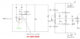
I own a HAPI 2 preamp designed by Stewart Hegeman. It features a time-delayed relay circuit on the outputs that provides an ~5 second delay after power-up before the preamp's output goes live. The problem is, the relays cause a terrible thump in my speakers when they engage and disengage.

The thump changes based on the capacitance.

  • With the circuit configured as drawn (the original configuration) the relays cause a loud thump when they engage and a louder thump when they disengage.
  • If I halve the capacitance, the thump is still slightly quieter, but equal on startup and shutdown.
  • If I double the capacitance, the thump is nearly gone when the relays engage, but very loud when they disengage.

When I changed the size of the cap, I expected the delay time to change, obviously. But I don't quite understand why it would effect the loudness of the thump, and why it would do so differently on startup and shutdown.

Can someone help me to understand it?

And is there are way to fix it (eliminate the thump)?

I know enough to basically understand how the circuit functions (R/C combo delays the transistor from switching the circuit on until the cap charges). But I don't understand it enough to figure out the above.

***Edit: I'm not 100% sure where exactly to fit this thread in the forum, but since this sub-forum is home to several threads about soft starts and circuits with a similar purpose, this seemed to be the appropriate place. Please pardon my error if it was not ***

attachment.php


attachment.php

Attachments

  • Circuit.jpg
    Circuit.jpg
    192.7 KB · Views: 727
  • IMG_20200205_155437.jpg
    IMG_20200205_155437.jpg
    81.7 KB · Views: 746

Quad 2 output transformer replacement

So I have a repair/refurbish of some original Quad II amplifiers.

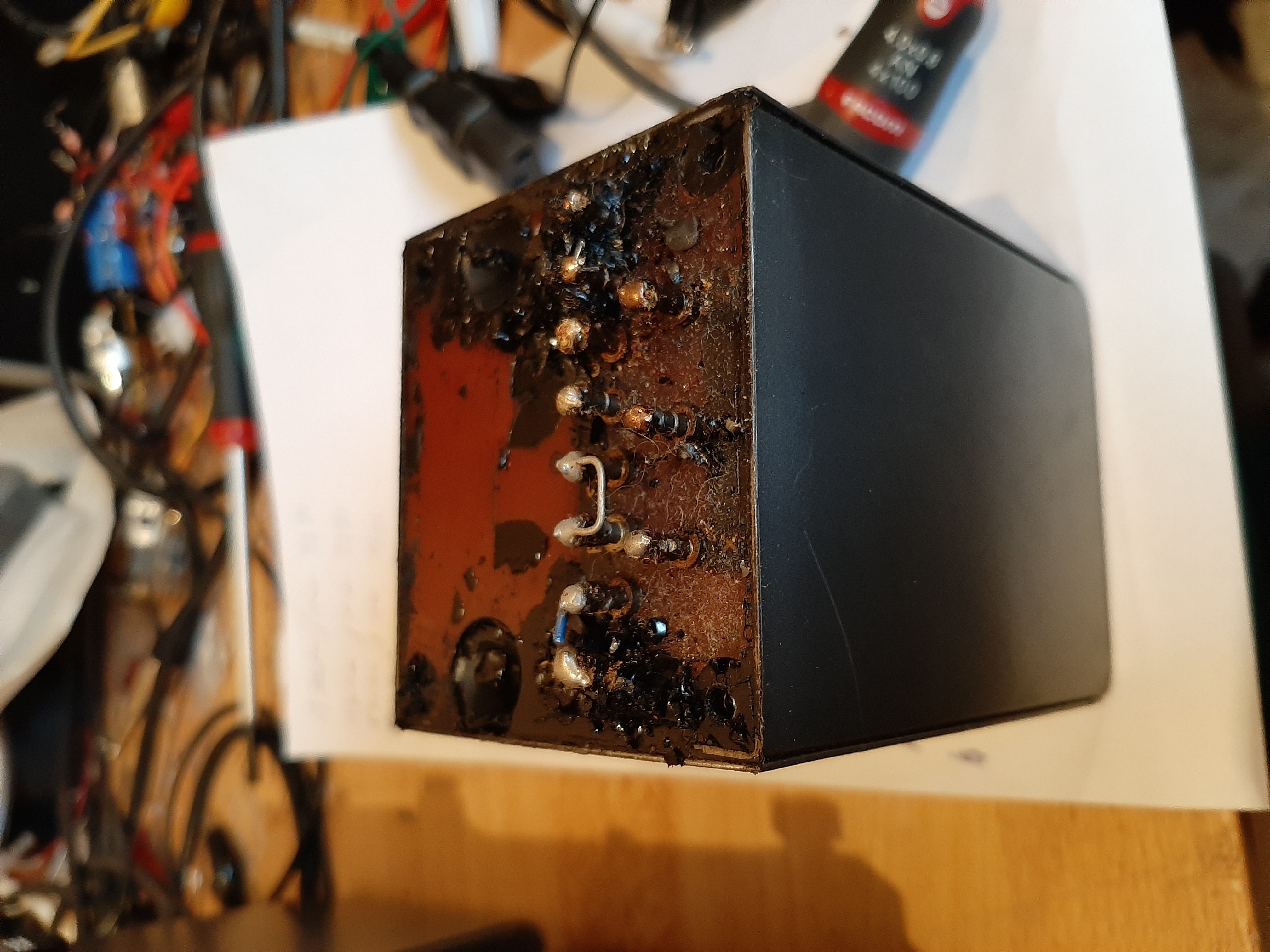
One of them is in decent condition the other one is under transformer goo.....
A picture of the OPT
quad.jpg


Power transformer is about the same. The inductor is better.
Measurement of DC resistance looks like they could still be good.
So I was thinking of getting alle the goo out (how would I do that? probably heating them...).
Or when I was reading it appears there is a company called majestic transformer who make complete replacements.
According to keith snook his website they should be better then the originals.
I also tought about using a lundahl that has CFB windings but then I also need to pot them etc.....

Anyone has experience with these replacements from majestic transformers?
When I would replace the opt's I would ofcourse replace them both.
Same goes for the power transformer.
The guy wants the amplifier in very good condition (= like new) so that is why I would take this route.
Al passive components will also be replaced.
For the tubes, they still hold the GZ32 rectifiers so these will go and a GZ34 wil fit in there.
As for the power capacitors, using the GZ34 I am replacing them with 47µF ones.
One of them still has the original GEC KT66 in them, the other one has 2 different kt66 brands in so was thinking about a new quad of them.

PecanPi and BOSC Demo - Boston, MA - March 14th 2020

Location:
Mattapan Branch of the Boston Public Library
1350 Blue Hill Ave
Mattapan, Massachusetts 02126

Time:
2pm

The demo will consist of the following:
2 x BOSC GaN Monoblock Amplifiers
1 x PecanPi Streamer
1 x PecaPi USB
2 x Infinity Primus P362 - Speakers

Demo attendees will receive discounts.

For more info on our products visit:
Orchard Audio - Home

Thank you to the Boston Audio Society for help in organizing this event:
BostonAudioSociety.org homepage

Facebook Event Link:
Orchard Audio PecanPi And BOSC Demo

Where can I find belts for Hitachi D-E66 Tape Deck?

Hi forum members, need your help to locate belts for Hitachi D-E66 Tape Deck, and advice to solve a problem with the FF/RW mechanism.

I have had it sitting around for several years, unused due to broken pulley belt, and the flywheel belt has become gooey and lost its tension.

Recently I decided to have a go at repairing it, but need some expert help.

The deck does not rewind nor fast forward, it plays OK with some temporary belts (laggy bands - I guesstimated the sizes) but there is a noise, probably due to the tension of the pulley belt being incorrect. I have not tampered with the mechanism other than replacing the belts, but it used to work fine until the belts perished.

Images: Hitachi D-E66 Tape Deck - Imgur

Any help or advice will be appreciated.

Help with Sony MHC-DX 10 CD assembly

Hi all

I have a Sony MHC-DX 10 Hi-Fi system, which I am repairing for a colleague of mine. The issue was that, the rubber band, which controls the opening, and closing of the CD Drawer, and 3 CD changer, had become extremely soft, and had basically melted, and needed to be replaced. Upon removal, and replacement of the new rubber band, I am now having issues, aligning the mechanism, so that the drawer opens, and closes, and the CD changer is able to swap CDs. Right now, it is trying to spin, but gets stuck, and won't open.

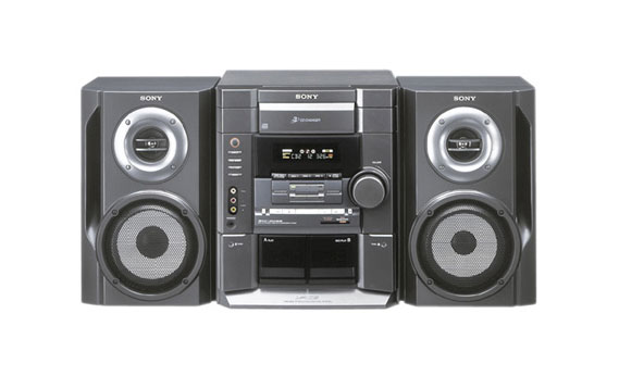
Here is a photo of the unit in question,
4a40f3bc3c0992a9cade57fe80c4265c.jpg


and here is a link to the service manual.
https://www.hobbielektronika.hu/forum/getfile.php?id=57775

I was hoping, that it would explain the order, in which to reassemble the CD mechanism, but no luck. |

If anybody is able to assist, we would be so grateful.

Thanks

TC-TB3 (Transistorized Tone Board)

Hi DIYAUDIO Friends , I make transistorized tone control (TC-TB3 Namec), It's working but l have little issue. When
I put this preamp on a surface little hum sound though speaker🔊, but when I lift preamp in air (air gap from surface) hum sound goes so far back. I used this preamp or tone control with AX11 and many other amp result same.
How can I solve this issue.
PCB layout and ready PCB pic uploaded.

Attachments

  • TC-TB3 Layout All.jpg
    TC-TB3 Layout All.jpg
    370 KB · Views: 507
  • TC-TB3 1.jpg
    TC-TB3 1.jpg
    141.5 KB · Views: 379
  • TC-TB3 2.jpg
    TC-TB3 2.jpg
    133.7 KB · Views: 372

fender blues deluxe reissue stuck distorting

hi,

I have a blues deluxe reissue that is stuck distorting

any guesses based on these measurements? all VDC unless noted. I'm also curious if the distortion is simply stuck on. i only hear one relay click

V1A
plate 197
grid 0
cathode 1.4
B
plate 194
grid 0
cathode 1.4
V2A
plate na
grid na
cathode na
B
plate 207
grid 14mV
cathode 1.2
V3A
plate 194
grid 18.9
cathode 28.7
B
plate 200
grid 19.5
cathode 28.6
V4A
plate 352
g1 0
g2 352
g3 -49VDC
cathode 3.6mV
V5A = same as V4A
plate
g1
g2
g3
cathode

Stetsom EX 3000EQ rectifier question

I have a Stetsom EX3000EQ in for repair. It had half of the power supply mosfets shorted with their center legs melted away as well as their gate resistors and half of the output mosfets were shorted.

I repaired the half of the power supply that was shorted and replaced the gate resistors and the driver IC for the power supply.

I replaced the shorted output mosfets and the driver IC for that bank.

I powered the amp up and it boots up and gives me a single flashing red LED. The power supply drive starts up initially and then stops when a fault is detected.

The single blink of the red LED indicates a short in the output section. I’m not finding a short anywhere in the output section.

I pull the single rectifier in this amp and it tests open out of circuit. It is a dual anode and single cathode design. 300 v 20amp (10amps per side)

The rectifier is STTH2003CT

I am wondering what would cause this rectifier to fail open on both sides or am I doing something wrong testing it with my DMM. Black lead on the center leg and red probe on the outer legs. Maybe my DMM doesn’t have enough forward voltage for it to conduct. I also check for continuity and it reads open.

Please advise,

David

Trying to fix a peavey PVi 4B

Hello Guys.
I'm trying to fix a peavey PVi 4B powered mixing console (4 channel in 1 powered out). Made in China.

Initially, one power transistor (2SA1943), 2 power resistors (33 ohm/5W) and a voltage regulator (7915, for the preamp section) had gone bad.
I replaced both power transistors (2SA1943 and 2SC5200) with exactly the same type, put 2 new 39 ohm/5W resistors (I couldn't get the 33 ohm ones) and put a new 7915 regulator in place. I checked all other transistors, diodes, resistors, caps, etc and they all seems to be OK.
When I turn it on, the outcoming sound is very low and distorted, as if a transistor is not working. I have to say that I did not replace the driver transistors (C2073 and A1837) since they measured OK on my DVM outside the PCB. At least the power amp doesn't blow up ...
When using the direct output, the preamp section works fine, except for the onboard digital reverb (it works but sounds absolutely nasty. It does not deserve the name "reverb"). I can't find the appropriate words to describe it, other than absolute crap...

I know that I'm missing something. Any help?

Here is a schematic of this amp. It's not a 100% accurate but that's all I could find.

Attachments

MC 2 Line

Some time ago, I was doing a design for an MM with no feedback,
using a one-stage transconductance. That worked just fine, so I
wanted to do the same for an MC pre-amplifier.
The problem is that all the design I've seen, (on MC head amps),
uses on or more large electrolytics, and I definitely wanted to
avoid that, so the challenge was to make an amplifier with
these basic features:

1)a gain of 80dB @ dc,
2)an input bias-current < 1muA
3)low noise
4)using easy to obtain components

The concept I was working from is as simple as it gets:


The dc-gain is defined as Ag = gm x Rl and with Rl = 33k5 in
the RIAA network and Ag = 80dB = 10,000x =>

gm = 10k/33k5 =0.298S (S = 1/Ohm).

The RIAA network is from Linsley-Hood as found on Elliot Sound
(sound-au.com/project25.htm), allthough I reduced the impedance-
level to 1/3, i.e. resistors devided by 3 and capacitors multiplied
be 3.
The design I came up with look like this (simplified):


The output of the LTPs (Long Tailed Pair) feeds into a combination
of a current mirror and folded cascode. With the R4,R5, and R6 as
specified, the quiscent currents of Q9, Q12 and Q6 are the same.
The same applies for Q1, Q4, and Q14.

The total gm from input to the RIAA network is :

gm = a x b c x Ic/Vt,

where
a = ½ as the input voltage is shared between each transistor
in the LTP,
b = 2 as there is two LTPs,
c = 3 well its just way the current mirror / folded cascode works,
Ic = the collector current in the LTPs, and
Vt = 26mV

Now we can calculate the Ic in the LTPs:

Ic = gm x Vt/3 = 0.298 x 26mV/3 = 2.58mA, and hence

R3 = R7 = (15-0.7)/(2Ic) = 2.77kOhm

Now, if you simulate (or build) the amp, the gain at LF/DC just can't
make it to 80dB. The problem is the Q6 and Q14 : the output impedance
is too low. This is dealt with in the full design.

A few words on the output buffer: The requirements of this buffer are:

1) A high input impedance, as not to load the RIAA network
2) Drive the output (!)
3) Low distortion.

1) states that Q17 and Q18 should run at a rather low Ic,
2) states that Q19 - Q22 should run at a "not too low" current.
3) The original diamond buffer had only four transistors, and
run at the same Ic, as this cancels out much distortion, albeit at
a rather high total current.

By adding two transistors, the output transistors can be run at almost
the same current as the input transistors, and still be able to drive
any "normal" amplifier down the line. Running at 560muA each this buffer
will drive a 5.8kOhm load to 13V and still stay in class A. It will
drive much lower load, but then in class B. It should be able to drive
a 825 Ohm load to 13V.

There is another issue: the ouput offset voltage. In the simplified
version, LTSpice calculates it to be app 1V. But this is with
identical transistors, and with physical transistors this isbound to
be much larger. After all, the DC gain is 10,000x so just a 1mv
difference in the input transistors, this will result in 10V at
output! This is dealt with in the full circuit.

The full circuit will follow in a subsequent post

Have a nice day!

Attachments

BIAS wont stay still

My active monitors have a bias that just can't seem to stay still... 🙂

The HF amp bias is rock solid, but the LF amp bias keeps jumping around.

The target is 15mV, across the 0.3ohm emitter resistor but , even after being on for an hour, the bias keeps jumping between around 11 and 18 mV

*Schematics attached

What is the cause?

Attachments

  • HF amp.jpg
    HF amp.jpg
    222 KB · Views: 178
  • LF amp.jpg
    LF amp.jpg
    245.2 KB · Views: 183

FS: Eminence, Selenium, and Fostex Used 8 ohm Imp. Speaker Drivers

SOLD - 4 Eminence Alpha-15A 15inch drivers. ($75/pair including shipping)
1 pair of Eminence BETA 12CX. ($50/pair plus actual shipping)
SOLD - Selenium D220Ti 1" Titanium Compression Horn Drivers - Made in Brazil. ($65/pair including shipping)
1 pair of Fostex FE 126E ($35/pair including shipping) The cone discoloration spots are not damage to the cone.

Attachments

  • Alpha-15A back.jpg
    Alpha-15A back.jpg
    334.3 KB · Views: 354
  • Alpha-15A front.jpg
    Alpha-15A front.jpg
    276.5 KB · Views: 350
  • Beta 12CX Back.jpg
    Beta 12CX Back.jpg
    284.3 KB · Views: 349
  • Beta 12CX.jpg
    Beta 12CX.jpg
    278.9 KB · Views: 335
  • Drivers Combo.jpg
    Drivers Combo.jpg
    251.4 KB · Views: 340
  • Selenium.jpg
    Selenium.jpg
    255.5 KB · Views: 134
  • Fostex.jpg
    Fostex.jpg
    185.2 KB · Views: 160

Phono preamp fix

Hello,
I gutted Non working NAD 701 that I had for its phono preamp.
It works pretty well with very good power supply, but I am trying to make it better and don’t know how to. Does any one know what parts to replace or take out of this circuit to make it better?
I don’t want to buy 100-200 dollar phono preamp just to find out its not better than mine.
Turntable is Thorens TD150 with mm Pickering cart and project debut 3 with stock Ortofon omg 5 e.
As a newb i need “buy this part and put it here or replace this part for that part”
Instructions.
Many thanks

Attachments

  • image.jpg
    image.jpg
    635.3 KB · Views: 281

Favorite Threads and Posts in "Class D" Forum

Favorite Threads and Posts in Class D Forum

This permanent thread is a place for links to threads or posts in this particular forum that are useful and/or exemplify the best of DIY Audio.

This is so others- especially newer members can find them. Feel free to post with these links and a brief comment on what the thread discusses. Occasionally the moderators will consolidate them into fewer posts.

Factory Glimpse - posted by Lundahl Transformers

Factory glimpse:
Victor Kung at VK Music challenge us to develop an upgrade transformer for the new TU-8800 tube amplifier kit from Elekit, Japan.
It turned out to be a more difficult task than what we expected, requiring three iterations before everyone was pleased.
Here is a sneak peek from the production of the new transformer, LL2783C.

from Victor
Mr Fujita said LL2L2783C is very (very) good...

getfvid_85627084_258327311823241_897145915683373056_n on Vimeo

This is LL2783C...


Philips cd880 problems

Hi,
have some problems with Philips CD880. Disc engine rotates anything else is dead -no display ,buttons don't work. This problem was earlier but resoldering helped .Now problem the same and resoldering mdidn't help .
Could someone tell which signals & need to have that player starts to work .& think first must be reset to servo processor and oscillator work but don't have service manual.
Thanks
Darius

Mid and High Cabinets to Pair with Super Scooper 18's

Hi Ya'll,

I am mid way through building some 18" super scoopers and it's time to start selecting some cabinet plans for speakers that can handle the rest of the audible spectrum.

Is there anything you might suggest that would work with all of the 15" subs I happen to have laying around in combination with purchasing some HF drivers to pop in the same cabinets? Perhaps a 2x15 cabinet with HF drivers on top would work? I'm looking for advice from more experienced systems builders. My preference is to have them stack tall on top of the super scoopers. I'm just unsure if a pair of 15's with HF drivers on top of each super scooper would be "proper" for good results. Maybe it's more wise to have a 10 or a 12 thrown into the mix.. Excuse my learning curve here.

Thanks regardless,
- JP

NAD 2200 current draw rises

I have a NAD 2200 PE that I am repairing/upgrading. When I got it the right channel had a number of fried resistors, and three output transistors (Q320,Q318,Q314) and R368- the emitter resistors were fried and the main PS caps were bulging. I have recapped the unit, and replaced the output transistors (I had some spare originals that I had pulled form another 2200, replaced all the fried transistors and any that looked that they have heat damage, and also replaced Q302/Q304 and Q306/Q308 as although they were of on the transistor tester I thought it better to replace them. I have also replaced SR 302. The rest of the transistors test ok on the right channel and the unit fires up and comes out of protection, and both channels pass signal. However, these units on idle (no input no speakers connected) should draw 0.4A approx. This unit starts there and then creeps (in small jumps to towards 0.75A- which is when I noticed a "warm" smell- and turned it off. I use a Senore PR57- which does not have current limiting. I tested the NAD with cold bias (Collector Q302 to collector Q304) to see if it was the output transistors, and the result is the same- the current creeps up. So although I have "fixed" the unit, I don not think I have found the underlying cause as to why the right channel self destructed. any thoughts or guidance would be greatly appreciated Peter

NAD C542 continuous issues

Hi Guys,
My 2 NAD C542's are driving me nuts, they both have 'similar' problem but I've no clue how to tackle it...recapped, whole drive mechanisms replaced, voltages measured - nothing helps. I'm wondering if they're suffering from a known failure?

Unit 1:
- Complete laser assembly replaced
- Power supply fully recapped except for the 12V one as this one has decent (Fine Gold) caps, measured the voltages - good
- Voltages measured - all OK
- Relays bypassed (just for testing purposes)

Problem:
- Sometimes it doesn't fully turn on, the green LED turns on and that's it. The other time it turns on, reads the TOC, then the 1st track but it's skipping through tracks, trying to change track or go from the first to last track sometimes it goes nuts and eventually shows -- ---- on the display.
- If it reads the TOC and you let it play untouched from 1st to last track, it will play the whole CD with no issues


Unit 2:
- Complete laser assembly replaced, still the same issue
- Power supply fully recapped except for the 12V one as this one has decent (Fine Gold) caps, measured the voltages - good
- Voltages measured - all OK
- Relays bypassed (just for testing purposes)

Problem:
- Turns on fine, CD spins but no sound from the laser and no TOC readout
- Every few seconds there is a short click from the relay, the voltage drops and comes back again, this can also be seen looking at the CD speed, it goes up and down every few seconds
- Very rarely it reads the TOC after a minute and plays but touching any button makes it lose it's mind

Understanding Class D Amps

I am a novice in designing class d amplifiers. I currently designing a class d amp with group of my classmates and we are confuse about how the amplification occurs. I know we need a gate driver to turn on the high side MOSFETs but when we applied the Pwm inputs to the gate driver the outputs is not a square waveform. After researching we believe that the gate driver will output the same Pam signal but with a higher output voltage and then send this signal to the MOSFETs for amplification.
Are wrong thinking the gate driver outputs a pwm signal?

Low-resistance block terminals for flea power amplifiers

I am wondering what brand or make of low-resistance block terminals the members here recommend for passive crossovers being driven by flea power amplifiers. I sourced a pretty good output transformer with a low-DCR secondary (.3 ohm) and am looking for similar low-DCR components for the passive crossover input/output terminals, or perhaps suggestions regarding which ones to avoid. And before anyone chimes in with it, yes, I am aware using an active crossover is the best low-loss alternative. I’m just here looking for best practices with passive loudspeaker crossovers.

Thanks in advance.

TSE II checkout issues help needed

So I finished building my TSE ii today and am having multiple issues with the checkout procedure. Any help at all would be greatly appreciated! So now for the issues:

-upon inital powerup, it ran for a few seconds and then there was a flash and smoke. I immediately turned the power off and found a burned mark between d2 and d3 on the bottom side of the board (see pic). I looked and did not see any solder bridge between the two nor was there any visual damage to either diode. This event also blew the fuse. I cleaned up the burned area and did not notice any other damage. I tested both diodes, both show .5v and only pass voltage one direction.

- I then replaced the fuse and tried powering up again. I am getting the following measurements with no tubes installed and have no clue where to start on the troubleshooting:

B+ 0v
B- -174v
rect heater volt 0v
300b heater volt 4.98v
5482 heater volt 8.3v

I have uploaded a few pictures of the build. Thanks again.

Bryce

Attachments

  • 20200120_175922.jpg
    20200120_175922.jpg
    934.1 KB · Views: 333
  • 20200120_175909.jpg
    20200120_175909.jpg
    935.4 KB · Views: 341
  • 20200120_165307.jpg
    20200120_165307.jpg
    653.9 KB · Views: 306

Pine Speaker Cabinets

I'm thinking of building a set of speakers based on the M5 Classic Two at audioexcite:

www.audioexcite.com >> Classic Two – M5

For cabinet construction though I was considering something a bit more retro 70's (B&O BEOVOX kind of vibe)

BeoVox 1200 Passive Loudspeakers

I hate veneering though and was thinking about the possibility of using solid pine furniture board for the top, bottom and sides of the cabinet:

Wickes General Purpose Pine Timberboard - 18mm x 200mm x 2350mm | Wickes.co.uk

I regularly use this for furniture building as it gets round a lot of the problems with cut/planed pine. It is straight, temperature and moisture stable and has a more uniform density.

Question is whether, combined with an MDF baffle and plenty of internal bracing, it would make a decent loudspeaker cabinet.

Anyone tried anything like this?

Cheers.

Can a pair of full range speakers replace LS50?

Can a pair of budget full range speakers replace LS50?

Hi all,

I have been listening to my KEF LS50 with my Yaqin MC-12S integrated tube amp. I love the sound coming out of them. Holographic, amazing sound stage, high resolution. In comparison to my other speakers including Polk Audio RTi4 and Klipsch RP-260, it’s night and day.

However I cannot afford to keep those expensive speakers and amp. I need to downgrade. I thought about elan UB5 or debut 6.2 but wanna see if there’s any other frugal solution.

I figure the full range speakers setup would be similar to the LS50 in the coaxial design (single point source)

Would any of these full range woofers can be comparable to the LS50 in term of holographicness,sound imaging, and resolution?

If so, which woofer would you recommend? I looked at the Mark Audio Alpair 7 and thinking to build a frugal horn MK3 for them.

Behriger umc204hd maximum input voltage

Hi all,

so I´m trying to figure out, what is the maximum peak voltage, that is safe for the line input of my sound card. According to Quick start guide -> https://www.fullcompass.com/common/files/24700-BehringerUMC404HDDatasheet.pdf, the max input level is 20 dBu, which is almost 11volts, which seems quite a lot to me compared to other sound cards. Am I missing something or is this right?

Thank you 🙂
Projects by fanatics, for fanatics
Get answers and advice for everyone wanting to learn the art of audio.
Join the Community
507,384
Members
7,867,973
Messages

Filter

Forum Statistics

Threads
405,276
Messages
7,867,973
Members
507,384
Latest member
RMCO