Silly Nusery Rhymes Twists From the Past

I still remember some silly nursery rhyme variations from my younger days.

Here are a few that come to mind. Please add more if you can remember them:

Jack and Jill went up the hill
Each with a buck and a quarter
Jill came down with two and half
They didn't go up for water.

Mary had a little lamb
And the doctor almost fainted.

Jack be nimble
Jack be quick
Jack jumped over the candle stick
And burnt his ***.

Heathkit Transistor Substitution

I started working on a Heathkit AP-1800 Preamplifier that lost the left channel. The included documentation of this preamp is very thorough, but many of the transistors have a proprietary Heathkit part number that I can't find information or datasheets on.
There many of these two BJT's used:
SM07275 (NPN) Heathkit Pt#417-283
SM62186 (PNP) Heathkit Pt#417-284

I pulled several and tested with a Peak DCA75 analyzer.

NPN's: Hfe 220-320, Vbe 0.770V, Vce 0.040V
PNP's: Hfe 230-285, Vbe -0.765V, Vce -0.070

BC547B/557B could be a possibility, but with so little info known about the originals, I'm not confident enough about this choice.

The PNP's have the dreaded black legs up to the transistor base with webbing connecting the three legs.
Any information would about substitute BJT's be greatly appreciated.

Attachments

  • IMG_3640.jpeg
    IMG_3640.jpeg
    542.5 KB · Views: 36

Howdy Yall!

I'm into home audio and all things nerdy and tech. I run a Classe preamp and amp, Magnepan front and surrounds, and 2x SVS PC-4000 subs.

I'm into cool gear and excited to see what people have got!

I'd like to tinker with some weird bluetooth modules and other components and have previously built a neat IR blaster to interface with my Classe CAV-75 since it doesn't have a remote 12v signal and can only take a pulsed turn on signal.

Amplifier Preamp Gain proportions how much db with tube pre and solidstate pre

I have been thinking about the gain structure of pre and power for a home theater amp or stereo amp with pre section being solidstate and tube

consider a tube pre with gain of 20 and power amplifier with gain of 20 log 33 or 30.37 db so how much this ratio needs to be where in tube pre I cannot change the gain but can change the gain of the power amp. I do understand the total gain ratio but what is the usual case i feel even amplifier with 26db is quite high if we have a tube pre with 20 gain

Another scenario with solid state pre with 6db gain and power amp at 30db gain so what is to be taken into consideration

For HT application
For Stereo application

Now do commercial HT amps comes with pre gain stage inbult? as the AV processor or receivers dont have a proper standard some give 1Vrms out and some are capable 3.5Vrms out
Can anyone please provide few inputs on this

That song stuck in your head…

It happens to me all the time.

Sometimes I wake up in the morning and it’s just playing for one reason or another…in my head.

There could be a million reasons I suppose. I could have heard it anywhere.

Sometimes I know where I heard it…sometimes I can’t figure it out for the life of me.

Sometimes it’s a song I love…other times not.

This morning it was “I’m gonna sit right down and write myself a letter”.

I quickly realized a version of it was playing in the background from the Eiji Kitamura Hit Kit Party while I was tinkering away at my workbench on my Iron Pumpkin project yesterday afternoon.

Funny that it was instrumental and so kind of just snuck in there without me paying much attention.

It actually made me want to hear the song and so I went searching for one of my favorite renditions which is by Madeleine Peyroux in her Dreamland album.

What’s bouncing around your head today?
  • Like
Reactions: vinylkid58

Quicksilver Mono Amp noise on startup

Hi everyone,

I made a trade for a pair of preowned Quicksilver Mono amps on the weekend. One amp makes an odd noise a few seconds after it is turned on. It only lasts a second then goes away, so I'm not sure if it's something I should be concerned about. It's a mechanical "whumm" sound and isn't coming from speakers. Kind of sounds like a lightsaber from Star Wars, lol. I've attached a video so you can hear it. The noise happens 12 seconds in.

Any idea what might cause this noise? I think it's one of the transformers, but I'm not sure. Amp seems fine otherwise, but I'm worried it could lead to bigger problems down the road if not dealt with. I also emailed Quicksilver, but thought I'd ask here as well in case I don't hear back from them. The seller said I could return amps if I'm not happy, so I'd like to make a decision soon.

Thanks very much.

Login to view embedded media

Ikea spherical speakers, first build done.

I thought I should post pictures of my first build.

Project was inspired by Cabasse and the curves employed in B&W 800 series, although on a much smaller budget. Had the idea to use bowls, Ikea had the wooden Blanda which seemed perfect. After scouring the net, found several others using these, although none using the 28cm versions. Design is an active 2 way design.

IK  001.jpg


First completed photo (no tweeter), initially using Zero class T amps.

An externally hosted image should be here but it was not working when we last tested it.


Current incarnation, using rotel 6 channel amp, channel for tweeter and mid, bridged for 15" sub, experimenting with solid oak sleeper stands and granite plinths.

An externally hosted image should be here but it was not working when we last tested it.


Tweeters rather delicate positioning on top, seems to be fine without an enclosure, however I am experimenting with casting tapering tubes using champagne flutes.

The Sound: To my humble ears they sound rather good, haven't obtained a microphone to do testing. Definitely better than my Mission V63, which have an rrp of over £500. The 'no baffle' 15" add good low level sound reinforcement, as they don't go terrifically low or have very much bass

The drivers are Peerless M16GH (link below to drivers and excellent seller from eBay) Peerless & CO M16GH/4 Mid Woofers X 2 New/OldStock. on eBay (end time 25-Jan-10 10:15:24 GMT)


The tweeters are also Peerless metal domes, model unknown.

Currently crossed at 15" Sub 20-150Hz, Mid 50Hz-3Khz, tweeter 3Khz-20Khz

The sphere's come in at around 8L, (9.1L before cuts and driver displacement) One has eggfoam stuffing the other is naked will aquire some different materials for testing when I have a good mic.

They need another sand down, better integration with the stands and experiments with internal wadding, and the new tweeter housing, when time allows.
  • Like
Reactions: AlmaAtaKZ

Converting soft start to work with maintained contact switch

Hi, I accidentally bought a maintained contact switch and a soft start that is designed for a momentary contact switch. Is there any way to convert the soft start so that it works with a normal switch
Here’s a link to the soft start that I am using
https://www.audiophonics.fr/fr/soft...et-protection-pour-amplificateur-p-10225.html
On the soft start there is a Texas Instruments NE555P which acts as the timer delay for the soft start but I’m assume it also gets the input from the switch.
When I read the data sheet for the ne555p it said you could use it in monostable or astable configurations. Is this what I need to look at to figure it out or can I just solder the switch into two points on the soft start to fix the issue?

Attachments

Da-capo issue (John W?)

John I was wondering if you came to any conclusion about the pink noise from the da-capo DAC from the post on the forum middle of last year.

I also have a Da-Capo which creates the same pink/white noise sound, with a hint of the music behind it, after a period of being powered up (doesn't seem to make a difference if it is in standby or not, just the power being plugged in).

The DAC has the HDCD filter fitted (so isn't the 1307 filter issue that you mentioned).

I have tried re-seating the filter module and moving the Input card to a different slot. Neither have made any difference.

Funnily enough about 4 – 5 months ago a Da-Capo came up for sale that must have been one of your development ones. The serial was no 1 and it had a dedication to your wife actully on the circuit board. If I had seen your name on these forums before now I would have let you know as it sold for silly low money…

Lastly I wondered if by any chance anyone might have a copy of the original Da-Capo instruction manual at all? I would really appreciate a photocopy of it (been trying to get one for ages), I am also looking for a Cardinal instruction manual as well…

Does anyone know the dip switch settings for the HDCD filter (or will I only get intelligible sound if I have used the correct setting)

What transport was the Cardinal based on… Yes I know the drawer etc is some bespoke low vibration material etc… but I guess the laser and motors etc. were taken from a commercially available Transport… It would be of immense help as I could then track down some s/h really cheap units that used the same laser and motors etc for future spares.

John can you remember if the cardinal produced performance figures (jitter etc.) better than most other transports produced, or is it just good figures for it's era?

Lastly is there any other transports that use a compatible clock lock to the Da-Capo DAC? Just wondered because at some point if the cardinal broke and it can’t repaired it would be good to know of any other transports that would work with the clock lock connection on the DAC.

Thanks for any info that can be offered.

John H

PS my Cardinal accepts CD-R’s without any drama (including the cheapest of the cheap CD-R’s), I haven’t tried RW’s but will later tonight.

harman/kardon AVR 255/230 no audio

Hello, I recently bought an harman/kardon AVR 255/230 second hand. I set it up, everything worked fine until I was setting up my Fire TV Cube to be able to control it. It tried to send some command where it switched sources (not exactly sure what it was trying to do, maybe it also had something to do with muting the source?) and since then there is no audio.
I have tried:
  • using multiple sources (HDMI, digital audio, analong cinch; both back and front panel ones)
  • factory resetting it with holding OK button (Tho there is a reset button in the back near the RS323 port, which I don't know how works)
  • tested speakers - there is no short
Additional information:
  • video out works fine
  • there is no error message on the screen (both built in and hdmi out)
  • while playing the test tone (speaker level setup) there is noise coming through the speaker at max volume
  • noise coming through the phones port while trying to play music at max volume
    • at first after the speakers stopped playing the phones port continued to work, however i disassembled it to look for burnt components / bad soldering points / overall loose things (found none)
  • I tried testing resistors labeled 0.27ohmKx2 5W KW0807 but was getting weird readings - all were 0.0-0.1ohm across them so I figure I was measuring them wrong
  • I tried testing transistors behind them (diode mode on multimeter) got readings: left to middle pin is 0.6v, left to right pin is 0.6v, middle to right pin is 1.2v - this is on the ones I could access (only two of them)

Anyone have experience with something like this? Any advice on what I should try / test? I have no problem disassembling it and sending photos of things / testing individual components.
In advance thank you for any help.

For Sale Lot of 10x high end Oyaide US/JAPAN plugs and more

hi there,
I want to sell a lot of US/Japan power plugs, the lot includes the following:

3x MPS HADES - new, unpacked, but unused, never installed on any cable.
2x Oyaide - removed from oyaide Black Mamba V1 cable and Oyaide power distributor. These seems to be unplated phosphor bronze. Used

5x Oyaide beryllium copper silver and rhodium plated. ---> these are truly special and you cannot buy them on the market. Shells are taken from other original Oyaide plugs (c037 and P004). These plugs (blades to me more precise) are made exclusively for AcroIink in Japan and were removed from US/JAPAN standard high end acrolink power cable.
Contacts: beryllium copper
Coating: polished silver + rhodium

these five plugs (blades) are IMO one of the best money can buy. I compared them to Oyaide P037, P004 . I dount count Furutech as generally speaking I am not NCF fan.

I have no usage for US/JAPAN plugs here in EU, therefore want to sell these.

400 EUR / 440 USD via bank transfer. economy worldwide shipping included. This is my best price already. If youre into DIY'ing power cables - try these five oyaide plugs and you wont be dissapointed.

Attachments

  • IMG_2550.JPG
    IMG_2550.JPG
    580.6 KB · Views: 131
  • IMG_2554.JPG
    IMG_2554.JPG
    335.3 KB · Views: 126
  • IMG_2553.JPG
    IMG_2553.JPG
    350.8 KB · Views: 117
  • IMG_2552.JPG
    IMG_2552.JPG
    426.5 KB · Views: 116
  • IMG_2551.JPG
    IMG_2551.JPG
    417.8 KB · Views: 124

Exploring Purifi Woofer Speaker Builds

A thread for discussion on all purifi driver builds.

A place to brainstorm and speculate on drivers and potential speaker builds for arguably, objectively, the best no-nonsense engineering-first traditional speaker drivers' money can buy - If you have a complete project underway, please start your own thread and post a link to it in here. Otherwise posting occasional random progress pics and info here is fine but we will keep full build discussion elsewhere.

We are also pleased to have @lrisbo of purifi occasionally check in and post here of which is much appreciated.

A tweeter is on the way 🤓

Updated 26/01/23: Added more build links and intro - (I may stop updating commercial builds moving forward as they are now coming in thick and fast)
Updated 16/06/22: Added builds and review links, updates to builds
Update 17/03/22: below


Time for a bit of consolidation due to this thread getting some hits, and purifi has now released quite a few scrunchy woofers

Links to known projects & commercial speakers using the Purifi drivers (please PM me if I need to add any)

Of course - www.purifi-audio.com , and the team behind the drivers here


Full DIY:

DIYA user @spresto9 has come up with these beauties with the 8" purifi woofer like to details and more pics HERE

20230125_122405-jpg.1134630


Check out this 4" pocket rocket proof of concept build from the Purifi team - all the info you need to DIY!

Spk8 appnote download (.pdf)

1649857222609.png


@lrisbo Proof of concept Purifi SPK4 (superseded) - Passive stand-mount

IMG_0194-2.jpg


@lrisbo Proof of concept Purifi SPK5 - Passive stand-mount - I believe these were at some point being made and sold commercially but have since been discontinued - there may be some floating around second hand market see here Celuaris SPK5 review ASR

purifi_spk5.jpg


@xrk971 PTT6.5/RS28F Waveguide Harsch XO - Passive stand-mount later evolved into a nice Stand mount and Floor standing Transmission Line

ptt6.5 rs28fwg.jpeg


@Joe Rasmussen Somewhat Legendary 'Elsinore' - Has been given an (expensive) purifi remodeling. Wow. Skip ahead to post #4,746 for the juicy bits.


Outback_Red_Populated_710W.jpg


Rick Sykora and team's Directiva - Active stand-mount with excellent (objective) reviews, requires external amplification for each driver and an external DSP crossover.

ASR Directiva Review Open Source Purifi Speaker.jpg


@xrk971 's Raal 70-20xr and PTT6.5 - this one the tweeter is not readily available to DIYers but there may be ways to get it if you're crafty.

(sorry X, couldnt find a finished pic, and I'm out of attachments for this post)


User tktran303's Collection of DIY designs here looking great

844c090c-c096-458a-a63d-a313c999c778-jpeg.1090990


Some mindfood for the 8" - a concept by Purifi.

1670006638175-jpeg.1115978


Paul Carmody's Virage - a full design, light on measurements but a fairly reputable designer.


.....and many more concepts within this thread, start reading. Most not fully documented or taken to finished stage though I suspect a few people are still perfecting their builds before showing them off. Remember you can drop people a friendly private message asking about how their progress is going.


DIY-Kits/Semi Commercial:


Yevgeniy’s PuriWave - 2-way stand mount with dual purifi passive radiators

PuriWave_banner_page.jpg


Troels Gravesen Purifi 6661 - Semi-passive/Active plate amplified floor-stander

p-6661-1.jpg


Troels Gravesen Purifi 6R - Passive bookshelf

purifi-1.jpg


Troels Gravesen Purifi Be - Looks like a revision to the above due to ribbon tweeter supply issues.

finished-1.jpg


hificompass Puri Bliss BeWg - Passive bookshelf - I believe the plans are/were for sale.

PuriBliss_BeWg_4.jpg


Joseph Crowe's 1198 - I believe you have to get in touch via the webpage - floor-stand transmission line

110749662_1199955657029489_1368727901282454175_n.jpg


Full Commercial:

March Audio Sointuva - arguably where "the bar has been set" for the Purifi 6.5 in a bookshelf chassis.

Sointuva17.jpg


Jones Scanlon Baby Reds - self powered studio mixing monitors.

Jones-Scanlon-Baby-Reds-studio-monitors-1920w-2.jpg


The Late Rick Craig's Selah Audio Purezza - A nice stand mount ribbon tweeter design, was available commercially but afaik discontinued, check SH market

116706749_971365439969612_5078393334836774399_n.jpg


Jachim Gerhard Surveyor's - stand-mounts , I believe there is/was a floor-stander made too

Rose_03-10-2020_0025-scaled.jpg


Dennis Murphy & Jim Salk's BePure2 - Floor stander - The legends behind the philharmonic BMR and BMR tower

a.jpg


and um, what ever this might be! https://www.audiocircle.com/index.php?topic=175599.0 - probably just a concept, I didn't read the thread. Likely Unobtanium tweeters and probably bottomless pockets required, if it is sold commercially.

Correction - the above was a concept which later evolved to the BePure2 - see this thread at AVSForums Post #10,174
https://www.avsforum.com/threads/th...rs-and-discussion-thread.939744/post-61186397


Further Build links:

Thrax Siren - a 2-way standmount

Jern 35 - 2 way standmount

Buchardt A500 Signature - Active 2 way standmount

WVL Serendipity - 2 way standmount

Taipuu Kero L active with FourAudio PPA-1000 dsp amps. - Not sure if available yet

Salk Sound BePure3 ... Holy **** I need to hear these.

a.jpg


Links to independent driver reviews:

https://www.erinsaudiocorner.com/driveunits/purifi_4/
https://www.erinsaudiocorner.com/driveunits/purifi_ptt65w04/
https://www.erinsaudiocorner.com/driveunits/purifi_ptt80x04-nab-02/ - the eight inch aluminum mid-woofer
https://www.erinsaudiocorner.com/driveunits/purifi_ptt6.5x04-naa-08/ - the 6.5 inch aluminum mid-woofer
https://www.erinsaudiocorner.com/driveunits/purifi_ptt6.5m-08-nfa-01a/ - the 6.5 inch dedicated midrange

Also - please consider visiting Erins Youtube Channel and subscribing! - a much needed light in the dark world of audio subjectivism.

https://audioxpress.com/article/tes...udio-6-5-midbass-transducer-from-purifi-audio

https://hificompass.com/en/reviews/purifi-audio-ptt65w04-01a-midwoofer
https://hificompass.com/en/reviews/purifi-audio-ptt40w04-01a-midwoofer
https://hificompass.com/en/reviews/purifi-ptt65w08-01b-ptt65x08-nfa-01
https://hificompass.com/en/reviews/purifi-ptt65m08-nfa-01a-65-true-midrange

http://www.troelsgravesen.dk/Purifi.htm


Original Post 02/04/2020:

With the group buys well underway the idea was bought up that a design thread be started to discuss build options.

Mine have arrived but I have no build materials and will not be able to get any until we come out of quarantine in (hopefully) three weeks time. I planned to start with a hybrid of purifi's SPK4/5 builds using the same AMT tweeter but maybe using a slot port with the 2.5khz crossover. That and I haven't done any AMT builds so it seemed like a good place to start.

I read of a guy in Aus planning on doing a line of passive and active speakers with the woofer so be interesting if he could chime in here.

So with no materials for the next at least 3 weeks, what better time to discuss build options! Fire away


20200402_103700.jpg
20200402_103908.jpg

Attachments

  • IMG_0194-2.jpg
    IMG_0194-2.jpg
    98.6 KB · Views: 648
  • purifi_spk5.jpg
    purifi_spk5.jpg
    229.2 KB · Views: 940

Apogee Scintilla - Another Project!

It is finally the time to post my Scinnies...

One Ohm model. One speaker OK, while other has bass ribbon panel damaged & removed...a multimeter fell onto the foil as I was completing the "Silicone fix" years ago (still have not gotten over it)...
  • Both tweeters are there and functional, albeit both ribbons appear stretched.
  • I do have a pair of replacement Bass Foils (actually the entire Kit) from Patrick in Germany that I bought many years ago (not cheap at $1300).
  • Covers are painted Matte Black (used to be that ugly Beige)
  • Been sitting in my back room past few years....wife would like them gone.
  • Pics taken years ago attached...
Pick up in West Sub of Chicago, no shipping. I also cannot assist on the repair.


Asking $1500.

Attachments

  • IMG_0139.JPG
    IMG_0139.JPG
    378.5 KB · Views: 279
  • IMG_0140.JPG
    IMG_0140.JPG
    531.9 KB · Views: 285
  • IMG_0141.JPG
    IMG_0141.JPG
    359.1 KB · Views: 277
  • IMG_0145.JPG
    IMG_0145.JPG
    614.7 KB · Views: 287
  • IMG_0146.JPG
    IMG_0146.JPG
    544.9 KB · Views: 293
  • IMG_0147.JPG
    IMG_0147.JPG
    610.3 KB · Views: 313
  • Like
Reactions: TheFinisher

question about the needle on the front of the Pass Lab XA60

Hello, I have two Xa60 mono blocks that I love and that I use for my Tannoy Kensington GR with a Mcintosh pre-amp. I bought them used some time ago from a professional. I wonder what the needle on the front is for, in fact when I turn on the device, the needle blocks towards the right, I don't know if this is normal, because I see an intermediate position at noon but the needle never went there. I would like to point out that I don't listen at very high volume. Thanks for help

VRDN: bipolar regulator PCB for line level ckts: ±11V to ±20V @ 1.5A with "De-Noiser"

VRDN: bipolar regulator PCB for line level ckts: ±11V to ±20V @ 1.5A with "De-Noiser"

A couple of diyAudio members and I perceived the need for a power supply board aimed at line level applications, such as for example Wayne's BA 2018 linestage. We felt it should include the following features:

  • Rectifier diodes on board
  • Transformer snubbers on board
  • Usable with both dual-secondary and single-secondary transformers (AC-to-AC wall warts)
  • True 1.5 ampere output capability, therefore: real heatsinks & big capacitors
  • Output voltages field adjustable via multi-turn trimpots

The result is a PCB called "VRDN" - Voltage Regulator with De-Noiser technology. The DN technology was originally invented and published by Charles Wenzel, whose original article called it "Finesse" (link) . DN technology was greatly improved and expanded by diyAudio member Elvee, who named the improved circuit his "De-Noiser" 
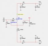
(link) This regulator PCB implements De-Noiser circuitry, as shown in the schematic of Figure 1 below.

Capacitor C13, and everything to the right of C13, are the De-Noiser. Jumper block J3 allows you to easily disable the De-Noiser (jumper installed) or enable it (jumper removed). This gives the pleasant option of performing a before-and-after pair of tests, either with measuring equipment OR with human listeners. Try it one way, then try it the other. Which do YOU prefer?

The board includes two transformer secondary snubbers, namely (MOV1, C1, R1) and (MOV2, C2, R2). Metal Oxide Varistors perform double duty in these snubbers, serving as the across-the-secondary capacitance "Cx" and also acting as voltage clamps, if an AC mains spike or surge occurs. The values of snubbing resistors R1 and R2 were chosen after performing several Quasimodo tests on several different transformers, and I expect these resistor values will work well IN THIS PARTICULAR CIRCUIT, with a wide variety of different transformers. However, if you wish to perform your own Quasimodo tests on your own transformer, and derive your own optimum values for R1 and R2, please go right ahead with my blessings and good wishes. Just remember to insert your actual MOV1 component into your Quasimodo's "Cx" socket.

Figure 1 includes two bridge rectifier components, BR1 and BR2. Each of these implements a "Full Wave" rectifier, meaning it transfers energy from the AC mains to the DC filter capacitors, two times per cycle: once at the peak of the mains sine wave, and once at the trough. The circuit contains two Full Wave rectifiers, one per transformer secondary. One of them produces the positive DC voltage output, and the other produces the negative DC voltage output.

However, when conceiving this board, we envisioned that some hobbyists might wish to build a bipolar regulated supply but feed it from an AC-to-AC wall wart instead. This has the great advantage that it keeps the mains voltage completely away from the DIY chassis; instead of 115VAC or 230VAC, the wires which enter the chassis carry only 16VAC or 18VAC, which is noticeably less dangerous. An AC-to-AC wall wart also allows a smaller DIY chassis with less interior volume, since the transformer is now outside rather than inside the chassis. But an AC wall wart is just a transformer with a single secondary.

VRDN implements the conventional, textbook method for creating a bipolar DC supply from a single secondary transformer. It's called a "Half Wave" rectifier, and as the name suggests, it transfers energy from the AC mains to the DC filter capacitors, only one time per cycle: either at the peak, or the trough, of the mains sine wave. One HWR generates the positive DC voltage output, and the other HWR generates the negative DC voltage output. Exactly as is done in the Objective-2 headphone amplifier, among MANY other examples.

To use the VRDN board with a single secondary, AC-to-AC wall wart, we need to make a few very minor adjustments. They are tabulated in Figure 2 below. As you can see, the only changes are to the list of stuff-and-solder actions. No PCB tracks need to be cut, no soldermask needs to be scraped off. You simply do-not-stuff six components, add three jumper wires (each 2.5mm long) into pre-labeled locations, and stuff two discrete diodes into existing & labeled thru-holes. It's easy.

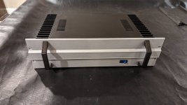
Figure 3 shows two VRDN boards. The top PCB in the photo is configured for a dual secondary transformer -- notice it has two green Euroblok connectors at the left edge of the board. One connector for each secondary. The bottom board is configured for a single secondary AC-to-AC wall wart. It has only one Euroblok connector and only one snubber at the left edge of the board. Everything else on the two boards is identical.

Figure 4 is a detailed picture of the input circuitry, on a PCB configured for two secondaries. Again notice the two Euroblok connectors.

Figure 5 is a detailed picture of the same region, this time on a PCB configured for a single secondary AC-to-AC wall wart. You can see that the bridge rectifiers are not stuffed, the (MOV2, C2, R2) snubber is not stuffed, and the Euroblok connector is not stuffed. You can also see that the three jumper wires "JOR1, JOR2, JOR3" have been stuffed -- look for pink arrows on the photo. Discrete Schottky diodes (5 amperes, 100 volts rated) have been stuffed -- look for gold stars. One diode is stuffed in holes "A" and "C", the other diode is stuffed in holes "L" and "M". Exactly as required by the options table shown in Figure 2.

The Jumper Options are shown on the schematic as 22 megohm resistors. This is a limitation of the CAD system and, specifically, a limitation of the CAD system USER, namely me. In truth, in real life, on your real PCB, JOR1 is either a zero ohm resistor (i.e. a piece of 22AWG hookup wire with white insulation) or else it is an INFINITY ohm resistor (i.e. an open circuit; nothing stuffed). Same goes for JOR2 and JOR3. Completely disregard "22 megohms" on the schematic. Ignore it. Pay it no attention. Simply remember that JOR1-3 are either opens or shorts. Opens or shorts. Repeat after me: opens or shorts. Look at the photos in Figures 4 and 5. Those options are either not-stuffed-at-all (open) or else stuffed with hookup wire (shorts). You can see them right in the photographs. Repeat after me: opens or shorts.

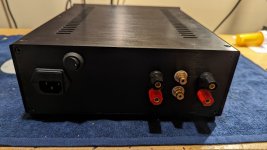
Figure 6 is a photograph of the output side of the PCB. Individual wire-to-board connections are provided for supply and ground, for each of two stereo channels. Also visible in this photograph are the vertically mounted resistors. This PCB uses the vertical orientation exclusively. Finally if you look very closely, you can see the amber colored Kapton tape on the back of the heatsinks.

TIPS FOR BUILDERS

Please carefully study the top silkscreen text layer when stuffing and soldering the 1N4004 diodes and the 1N4148 diodes. There is a little "A" next to each hole where an Anode is soldered. You'll find that on every 1N4004 and 1N4148, the cathode (band end) of the diode is the short wire which is stuffed straight thru the PCB with no bends; the cathode is the "butt end" of the vertical diode. The anode wire is the one which is bent into a 180 degree U-Turn, and is exposed for easy probing. The anode wire goes into the PCB hole with the little letter "A" on silkscreen.

First stuff and solder all resistors and axial diodes. Second, stuff and solder the MOVs and the bridge rectifiers (if using!!). Third, stuff and solder the Euroblok connectors and the two pin headers J3 and J4. Fourth, stuff and solder the small (non 2200uF) capacitors, the trimmer pots, and the transistors. Fifth, stuff the regulators-on-heatsinks (next paragraph).

After you bolt the LM317 and LM337 to their heatsinks, including the Sil-Pad insulator and the insulated shoulder washer / bushing, I recommend that you test-fit one of them into the PCB. You will discover that your unmodified assemby doesn't quite fit! You'll need to modify it. Bend the leads of the TO-220, backwards (towards the heatsink) about 1-2 millimeters. Try this. Aha! Now it fits. Put a piece of Kapton insulating tape on the back of each heatsink, over the TO-220 mounting bolt. The two heatsinks are positioned back-to-back and we don't want them to come into electrical contact. Kapton tape prevents that.

Stuff the regulators-on-heatsinks so the heatsink edges are flush with the PCB, but only solder the IC legs for now. Do not solder the heatsink mounting pins yet. Instead, turn the board right side up and look at the heatsinks placed back to back. You want to see a nice wide air gap between the two heatsinks, about 3-6 millimeters wide. When building my boards, I folded a sheet of paper in half, and half again, and again, etc., until I had a bundle 5mm thick. Then I jammed this paper bundle down between the two heatsinks to create a definite gap between them. With the paper in place, enforcing a nice gap, THEN I soldered the four heatsink mounting pins in place. After the solder joints cooled, I removed the paper bundle and voila! A nice, permanent, air gap between the two heatsinks.

Finally, stuff and solder the twelve 2200 microfarad capacitors.

SUMMARY OF FEATURES AND MIS-FEATURES

  • De-Noiser circuit with jumper enable/disable
  • Diodes on PCB
  • Transformer Snubbers on PCB
  • Big capacitors on PCB allowing true 1.5A output
  • No bleeder resistors on PCB
  • Voltage regulator ICs mounted on heatsinks for true 1.5A output
  • Heatsink thermal resistance is 8.6 deg C per watt
  • This is a four layer PCB, three of which are ground planes
  • Gerber CAD files freely available, send to any fab you wish
  • No "pilot light" LEDs on DC outputs
  • Can use with either dual secondary trafo or AC-to-AC wall wart
  • No SMD components; 100% thru-hole
  • PCB unique identifier is TZPTR7 ; suffix -A means "revision A"
  • PCB mounting holes compatible with Modushop chassis baseplate
  • Board size 62 x 142 mm (edges) ; 50 x 130 mm (holes)

NEW INFORMATION
  • 2023-12-21: a Forum member has created a new PCB layout of VRDN with only two layers. He has made the Gerber files freely downloadable in (this thread). Be sure to read his Disclaimer and non-Guarantee at the bottom of post #1.

Attachments

  • Figure1.png
    Figure1.png
    123.9 KB · Views: 12,433
  • Figure2.png
    Figure2.png
    26.9 KB · Views: 11,535
  • Both_Boards_together.jpg
    Both_Boards_together.jpg
    537.7 KB · Views: 9,067
  • Dual_Sec_options.jpg
    Dual_Sec_options.jpg
    641.3 KB · Views: 8,197
  • Single_Sec_options.jpg
    Single_Sec_options.jpg
    740.5 KB · Views: 8,756
  • Output_Connector_View.jpg
    Output_Connector_View.jpg
    381.7 KB · Views: 7,038
  • parts_list_VRDN.zip
    parts_list_VRDN.zip
    7.4 KB · Views: 1,753
  • TZPTR7_A_VRDN_regulator_rev_A.zip
    TZPTR7_A_VRDN_regulator_rev_A.zip
    189.8 KB · Views: 1,829

Monitor Audio One recycling project

Hi there!

Inspired by the Monitor Audio Monitor 3 enclosure recycling project


i am thinking about the recycling of a very old pair of Monitor Audio Monitor One speakers

OldSüeakers.jpg


I have some very different chassis already available for the exchange of the old chassis

I have a mini DSP 2 X 4 HD box and still struggling with the power amps

best thing would be to flip to something like Hypex FA122 but for the first development approach i will probably use the power amp section of an old Yamaha AV receiver

Yamaha-AV-Receiver-as-4-Channel-PowerAmp.jpg


next post with some options about the new chassis

I have the CLIO pocket measurement system and unfortunately a big lack of ability to use Vituix CAD but a dozen of years of experience with Visaton Boxsim
  • Like
Reactions: AlmaAtaKZ

6C33C SET Monoblock

Greetings Friends. I've been fascinated by the 6C33C since I first laid eyes on it, and I've been kicking around an idea for a simple SET amp featuring the triple nipple. Borrowing the driver (and schematics) from the 6336 SET Amp by @Suncalc this amp uses cathode bias and the high voltage swing driver to make ~15 watts of Class A power.

6C33C_MONO_AMP.jpg


Edcor's CXSE25-600 is a 25-watt OPT with a 600 ohm Primary and 8 ohm Secondary. According to my dummy math, 360v to the OPT will give a Va-k of 250v and a Vk of 88v, with a 400 ohm Kr.
Eliminated the volume control from the input, replaced with a 250k resistor.
Grid Leak Resistor for the output stage changed to 200k. Grid Stopper necessary?
Not sure how to calculate the K bypass cap.

6C33C_MONO_PS.jpg


Surprisingly the Hammond 372JX provides all the power needed. The output stage's cathode resistor eats so much b+ that there's no problem getting the 300v for the driver stage.
Enough capacitance for such a large current draw?
Better to take the driver stage power from before or after the 2nd choke?
Thoughts?

thanks for taking a look!

w

Building Euro21 801A tube preamp

Building Bela's aka euro21 801A preamp https://www.diyaudio.com/community/threads/801a-tube-preamp.395883/

I will use Ale's Moglia aka Bartola Hybrid mu-follower as anode load.

I will need to mod the Vout LT PSU for filaments, I have a couple of Lundahls Filament Current Choke LL1694 that can be configured as serial or parallel also common mode choke and choke input. Could be configured as choke input CMC?

More questions will follow.

TIA

Philips CD104 tweaks

Hi,

Planning to mod my CD104.

Anyone suggests any mods ? I have replaced the captive leads.

I was thinking of first looking at the capas in the analogue section. My main problem is how you get the analogue board out . I figure you go in from underneath and remove a torx screw holding the board in place. Is there much more dismantling to be done , or is there a special way of removing the card ?

Bipolar regulator PCB with "De-Noiser", a different PCB layout from the known schematic

Recently I came across Mark Johnson's thread "VRDN: bipolar regulator PCB for line level ckts: ±11V to ±20V @ 1.5A with "De-Noiser" "
https://www.diyaudio.com/community/...l-ckts-11v-to-20v-1-5a-with-de-noiser.355883/
and instantly became a fan.

Here is a redraw of his schematic done just for fun. I named it "Butterfly DN". The PCB can be made by hand if you like, it has only two layers.

IT HAS NOT BEEN TESTED YET!

I have ordered some PCBs and will be testing soon.

I will be updating this thread with pictures.

For how to set it up, please visit the first post of the original thread:
https://www.diyaudio.com/community/...l-ckts-11v-to-20v-1-5a-with-de-noiser.355883/
BOM, Part numbering on the PCB and component sizes are exactly the same.

Heat Sink thermal resistance: 6.2C/W - 11.4C/W, depending on the length of the heatsink used (ref. attached pdf)
Board Size: 103,5mm x 91,5mm


Added:
  • Optional half rectification diodes D98 & D99 have their own place on the PCB. Remember, they are only used for half rectification, when using a transformer with only ONE secondary. They are marked with a *
  • Added an optional resistor (R23, R24) in parallel to every one of the Variable resistors (VR1, VR2), in case you want to replace the Variable resistors by a fixed one.
  • 2x Outputs, CON1 and CON2. CON1 supports many readily available connectors. CON2 supports Faston terminals OR Europlug
  • Added R100, a way to connect the ground plane to chassis via the top right mounting hole. You can short it or use a resistor 3-10ohm

Have fun!
Alexander

Disclaimer
This thread is made by a fan, it is not affiliated in any way to Mark Johnson's work and the original VRDN thread.
This layout is a DIY project done by me, provided "as is", with no official guarantee it will work.

Attachments

Another corner array project

In the next few months I expect to start the build of a corner vertical array pair of speakers.

This will be used in a fairly small lounge living room with multiple sources, digital and analogue.

  • Vinyl
  • CD
  • Streaming, media etc
  • TV
  • Computer files
My hopes and expectations are.

  • To put them right in the corners, out the way. I took the pic attached when moving the furniture around just to show where they would go, right in the corners outside where the current speakers are standing at the time of the picture. I should explain that the current speakers are not normally diverging and the polystyrene sheet next to the TV is just old packaging! – the sound bar etc would go. The room is very asymmetric, the left “corner” of the listening area being created by a pillar that holds the structure for upstairs. I don’t know what happens with the structural beam running across, in terms of reflections.
  • To significantly exceed the sound quality available from commercially available loudspeakers.
  • To reduce to a minimum the listening position sensitivity one normally finds with two speaker stereo speakers, which I understand these should help with.
  • To hear some of the magic attributed to vertical arrays of full range speakers.
  • Ultimately to make it fairly simple to operate and control, remotes for source and volume would be nice.
  • I imagine my project would be a decide, design and build and use project, not numerous constant experiments, and so would not follow the depths and details of projects like the two towers, admirable though I am sure they are.
I need to decide what to build, I have taken some ideas from kind, patient and encouraging friends and read about the Roger Russel IDS 25, and I have looked carefully at Murphys Corner array. I have read lots of the threads on the forum and it’s fair to say one can easily become confused!

Consequently I thought to start a thread that others might follow later if they wished.

Some current outstanding questions for starters are;

  • Amplification, I have an existing old Musical Fidelity A100 that might be pressed into service?
  • EQ, I have no experience other than that gathered from operating my Hypex plate amps that drive the bass and provide room EQ of my 3-way system I built a few years ago to the Troels Gravesen Fusion design for another room. So I have the UMIK1 and measured and adjusted to achieve a reasonable in room plot with those.
  • I have read about different wiring, shading etc and am rapidly moving out of areas I understand!
  • Currently I would intend to build a wooden cabinet (maybe black MDF) version of Murphys Corner array or some of the others, with around 50 (25 per side) Vifa TC 9’s, and move on gradually from there.
  • If I build a cabinet with 25 units at 83.7mm each that totals 2092.5mm and the room is 2425 high. What happens to the remaining 332.5 mm, a little bit for the base etc, but then the arrays are not fully floor to ceiling, does this matter?
  • I understand its sensible to buy some spares, so maybe 55 units, I wonder if I can get a reasonable price somewhere on that number?
  • I have read of volume per unit at 1.5 to 2.7 litres, some sealed some not………..To fit the corners neatly the small end would be easier, a triangle section or similar with knocked off corners.
  • If the cabinets are suitably designed they could bolt into rawl bolts on the walls to keep them as rigidly mounted as the walls?
  • A black grille finish, as seen on threads appeals to make them as inconspicuous as possible.
  • A foam/felt strip either side of the driver lines might keep the grille/cover at a reasonable clearance and deal with some edge effects satisfactorily?
I am comfortable with the woodwork and simple electronics.

I have read a good part of the many threads and contributions and would greatly appreciate input of guidance, knowledge, experience and expertise from those of you who have the kindness and patience!

I would then document decisions and results as they come along.

Many thanks in advance

M

20240222_184055.jpg

New Member in Chile

Hello Everyone, Thanks for accepting me. I'm from the US and retired in Chile. I've been interested in Hi Fi audio since my 20's using primarily Sansui, Teac, and Akai components. Alas, all that equipment was sold long ago and I can't replace it with my current budget. So I've decided to try my hand at DIY and buying some kits online. Will see how it goes and maybe learn something along the way.

PCB or not PCB, this is a problem

hi All,


I'll explain right away that this is not about any kind of design, vector, cutting, milling or anything else - I have any design and drawing program for work experience and staying in a home made creation, I wanted to understand from you, crossover experts, what you use and how you make them.

I made one with the multi-hole base, but I won't show it to you otherwise you'll laugh until late, very late 🙂

Help With a PCB Project - Passive Volume Control

Hi All,

I am a total noob at electrionics and audio gear. I'm hoping to learn some new stuff by working on this first project. Basically I have an Audio Technica LP60X that outputs a signal at around 36dB LINE (100mV @ 1kHz) and currently it goes to a set of Logitech desktop speakers with a max input rating of 10W and a continuous rating of 5W RMS. (I know its probably an insulting setup to any harcore audiophiles but Im working on a budget).

My goal is to create an ESP32-S3 Mini 1 controled PCB, which will act as passive volume control in between the turn table and speakers. It does not need to amplify the signal, just be able to fade out and then fade back in using the ESP's wifi function and a digital potentiometer. I did some consulting (chatGPT and Youtube) and settled on using the MCP4231 as it seems to be the only chip that can handle stero input with single power supply and SPI control. (its also cheap).

The plan here is something like this: Audio from record player --> Passive Wifi-enabled volume control --> Speakers

I have attached a schematic I drew up in KiCad. Would you be able to look it over and let me know if there are any crucial errors I might be missing? Also if you have any tips/tricks or recomendations that would be appreciated too.

Kiitos! (Thank you so much in Finn)

Joel.
Screenshot 2025-04-01 163738.png

For Sale Pair Faital 12RS430, pair 10RS430, pair 8RS340

One lightly used (no scratches, never abused) pair Faital 12RS430 woofers. Very nice curve for a big-motor twelve, high x-max & Qms, deep bass, Faraday ring. $370/pair + shipping. https://faitalpro.com/en/products/LF_Loudspeakers/product_details/datasheet.php?id=151050115

SOLD: One lightly used (no scratches, never abused) pair Faital 10RS430 woofers. Same excellent motor and high Qms as 12RS430 on a lighter 10" cone. $340/pair + shipping. https://faitalpro.com/en/products/LF_Loudspeakers/product_details/datasheet.php?id=151040095

One lightly used (no scratches, never abused) pair Faital 8RS340 woofers. Easily notchable 1.5 dB bump @950 Hz, otherwise smooth to 2.7 kHz. $250/pair + shipping. https://faitalpro.com/en/products/LF_Loudspeakers/product_details/datasheet.php?id=101030204

2way becomes 3way with HIVI DMB-A dome mid

I find two problems with the DMB-A mid, which are at the low end (resonance) and high end (distortion?)of it's useful range. I will address these a bit further-on here.
I have not put the driver into it's intended system yet. The plan is to modify the 1976 vintage AR-16 to a 3way. The mid+tweeter will be overkill as far as power handling, but the parts don't cost too much, and I thought that it would be interesting to see what lowering the woofer crossover to 800hz (from1500hz) would do for the sound. The 8” sealed AR-16 should have satisfying bass near the wall, and should accept tone control boost gracefully at reasonable levels. The cabinets are only about .64cuft internal volume. System sensitivity should be about 85db. I will make the cabinets nice looking walnut veneer; stock they are dated-looking vinyl wood grain.

On the upper end, distortion seems to limit the DMB-A to about 4500hz. Super low distortion until about 5khz, then up it goes, dramatically. Is this breakup, or is something wrong with my test set-up? There is a few dB dip in FR around 4300hz

Have others noticed the rapid rise in distortion? I wonder: Could it be my settings in ARTA? I have checked advanced Windows settings for mic and speaker through Sound blaster card, are all at16bit/96khz.

I am OK with crossing to a tweeter at 4500hz, I just wonder why I see distortion rise so quickly.

I did get it to roll-off well enough, but that was by using a parallel notch filter---1.5uF/.14mH/30ohm. For some reason, the calculator I used gave very different values than these, so these are the result of trial and error, with measuring.

For others working with the DMB-A: To tame/roll off the low end resonance/ response; here is a starting point that looks good for an 800hz high-pass: 20uFseries cap plus a series notch filter (parallel with the driver): 40uF/1.2mH/3.3ohm

This looked good after measuring/swapping parts; I did not do a simulation.

Too bad it is hard to find “acoustic suspension”(compliant suspension, Fs/Qes below .5) woofers like the vintage AR units nowadays. Seems like Dayton could sell an 8" steel frame for $40-$50 retail, if they wanted to. Maybe the cones/spiders/surrounds that are easily available overseas don't have the characteristics required?

Ported speakers are popular, but I find that sealed lets me hear the deep bass notes more clearly, even though the mid bass may not be so powerful. Dayton, and others, have drivers that work in sealed boxes without DSP, but they roll-off earlier on the low end, and most have more breakup in their upper range. Highly successful vintage 2ways, with larger woofers, tended to have woofers that rolled-off more gracefully on the top end. They did tend to have less distinct mid-range sound though, likely due to more internal damping of the cone material.


.
  • Like
Reactions: andyjevans

3-Way Crossover/EQ Set-Up (Using Hypex Filter Design)

My cabinet conversion is nearing completion and I am getting ready for set up.

As a newbie, I am in danger of trying too many things at the same time and therefore getting confused. So I have to try to move in clear, simple steps, in the right order of priority, with clear objective, constraints and method for each.

So far I have the following plan which is limited by my current level of knowledge. I was mainly using this thread by @AllenB for guidance (although it goes more into passive filter design and is not specific to active filters) and I am now trying to make it more specific to active/DSP. I also used advice given in the build thread so far by @Busdriver02, @svp, @temp25, @Juhazi, @hifijim. I would like to build this guide so I can follow it myself and also make it available for others to use with DSP-based 3-ways. Would appreciate if experienced people can have a look and help me put it together.

Attachments

Another Chinese PP amp

Hello all. I built a Chinese PP tube amp I have had laying around for a few months. As we know there are no instructions aside from the schematic they send with it, which isn't great.

I followed as best as I could here: https://www.diyaudio.com/community/threads/problems-with-chinese-pp-kit.353111/

I have the transformer marked as 110v, same or similar to the one in post #98 in the above link. I am still not sure how to wire the primaries or the 2 yellow and one black (Yel-Blk-Yel). They show going to the 6.3v/0 and I assume the black go to chassis ground. And the primaries? Red-Blk/Red/Blk. I see only 6+ volts on one of those primaries. Are they marked incorrectly, perhaps?

For Sale Miro TDA1541 USB-I2S Stackable DAC

This is a very compact and cool looking TDA1541 DAC for your consideration.
I am providing quite a bit of details, so please read with patience.

The first thing to note that the TDA1541 chips are de-soldered from Cambridge Audio CD2.
I have obtained it from a very kind member here, I only paid for shipping from UK : TDA1541
The chips came with the boards, with aluminium plates glued on as heatsink or other purpose that i may not know.
As i removed the aluminium plates, most part of the prints on the chips were stucked to the adhesive used.
1742991026553.png

1742991230220.png


1742991280531.png

1742991320660.png


The chips were all removed by me, no pins are damaged, all in full length and clean.
20250326_193928.jpg20250326_194052.jpg20250326_193848.jpg

If you mind the cosmetics of the TDA1541 chips, then this DAC board is not for you, I suggest you skip this post.

More details of the DAC board in the post below.

Attachments

  • 20250326_194056.jpg
    20250326_194056.jpg
    340.8 KB · Views: 45

What's best forum...

Here's a list of various drivers I've tested. The vast majority are garbage tbh. I don't intend to update this list or publicly rank drivers going forward though hopefully this list provides some benefit to diy builders of the world. I've ranked those which I prefer in the top section. Then beneath are those which I find "good" and below those are garbage labeled "The Ugly". There are a handful of drivers in the ugly section which I intend to retest at different less strain inducing crossover bandwidths though the vast majority of my sentiment is specified here albeit a bit negative. I haven't tested every driver ever and there are certainly many gems to be tested that are not on this list.

Call it conspiracy or what you will... There's an inner circle of pagan colonialist imperialist federalist guitar worshipers who seem to hold chair as gatekeepers of various audio industry related things and speaker gear. These people may also happen to be stingy as hell. That fact aside, as such, many of the best products, high sensitivity low mms cone drivers for example, are disguised within the realm of guitar speaker drivers. Two example companies are Celestion and Jensen. Both make some fine drivers and again some junk... The ladder makes at least a couple drivers that I consider to be among the best and competitive with any I've tested. The brands which I consider to be honest, science oriented and therefore gain the rank of S tier are: Visaton, Fostex, Beyma, Mark Audio and Seas. Of similar quality though presenting a less consistent and or less focused and or less updated product line are Jensen, Ciare, 18Sound, LaVoce, Kartesian, and Faital. Oberton, PHL, and Audax seem to be landfill grade. B&C, Eminence and Celestion exhibit an imperialistic monopolistic political brand identity that I deem gross and reflective of oil baron level greed and orkishness. Through the lines I observe some sort of mining union business scheme clinging to stale traditions as though somehow holy, and claiming both land rights and music as of their own invention. Celestion does make some good products available to the masses... In general my preference is for less landfill quality quantity best business practices stagnant christian values anal retentive control freak bs. Preferable would be zero corporate influence in favor of scientific progress, though also an acceptance that we're dealing with mundane devices here, and if applicable achieve quality through real innovation.

Here's a simplified list of my favorite drivers in order of preference from best to worst. With regards to crossover frequency and driver size selection I am mostly optimizing for midfield level playback.

Sub Woofers // ~0hz-~50hz
-18Sound 15W500
-B&C 8PE21
-Seas H1878-08
-Visaton W200

Low Mid // Mid Drivers ~+40hz-~+1200hz // FR
-18Sound 10NMBA520 // 18Sound 10MB400
-Fostex FE206NV2
-Beyma 8MI100
-Visaton B200
-Seas Exotic W8

Mid Drivers // ~+600hz-~+10000hz
-Visaton B100
-Visaton B80
-Mark Audio CHN-40P // CHN-50P
-Kartesian Wib70_vPA
-Bliesma M74P-6

Tweeters // ~+1200hz-20,000hz
-Seas 22TAF/G
-GRS PT6816-8
-Visaton SC4.7ND
-Visaton DSM50 FFL

Full Range Drivers
-Fostex FE206NV2 // Unnamed favorite
-Visaton B100 // B200
-Mark Audio MAOP 7
-Mark Audio CHN-50P
-Jensen 10 Tornado Classic 100

Compression Drivers:
2":

-JBL
-Beyma CP800TI
-TAD TD4001

1.4":
-Beyma CP755ND Al
-Great Plains Audio 288C

1":
-Faital HF108
-BMS 4552
-Kartesian CMP35_VPA

———————————————————————————————————————————————————

Here are two additional lists of drivers which I tested for my project. The "Good" list are drivers which I found to be very performative though inferior to the my "Favorite" drivers. And the "The Ugly" are drivers which I found to be inferior:

Good:
Tweeters:

-Visaton BF32
-Visaton BF45

Bass // Mids // FR Drivers:
-Atlas PD5VH
-Beyma 12XA30ND
-B&C 8PE21

-18Sound 6ND430
-18Sound 10MW400
-18Sound 12NMB1000
-B&C 6MDN44
-B&C 8FMB51
-B&C 8MBX51
-B&C 10PE26
-Beyma 8G40
-Beyma 8MC300ND
-Beyma 8MC500ND
-Celestion CF0820M
-Celestion CN0617M
-Celestion G12H 55/75 Heritage
-Faital 6PR160
-Faital 8PR155
-Faital 8PR210
-Faital W8N8-150
-Fostex FE83NV
-Fostex FE126NV2
-Fostex FE166NV2
-Fostex FF105WK
-Fostex FF165WK
-Jensen 10 Mod 70
-Jensen Classic 100 Tornado 10
-Jensen Classic 100 Tornado 12
-LaVoce FSN020.71F
-Mark Audio Alpair 7MS
-Mark Audio CHN-40
-Mark Audio CHN-110
-Mark Audio CHP-70
-Mark Audio CHP-90
-Mark Audio CHR-70
-Mark Audio MAOP 5
-Mark Audio MAOP11
-Monacor SPH-102KEP
-Oberton 6NM150
-Purifi PTT4.0X
-Purifi PTT6.5M08
-Seas CA18RLY
-Seas CA22RNY
-Seas ER15RLY
-Seas FA22RCZ
-Seas OR002-04
-Seas OR004-04
-Seas OR005-04
-Seas OR006-04
-Supravox 165 GMF
-Supravox 285 GMF
-Visaton SL713
-Visaton W130S
-Visaton W170
-Visaton W250
-Visaton W300
-Wild Burro Betsy
-Zenith 49CZ852

Bass:
-18Sound 12MB1000
-B&C 10MD26
-Beyma 15G40
-Beyma 15P80FE/N
-Beyma 15MI100
-Seas CA22RNY
-Seas L26ROY
-Wavecor SW270WA1

Compression Drivers:
-18Sound 1480A
-B&C DCM414
-B&C DCM50
-Beyma CP22MF
-Beyma CP385ND
-Beyma TPL200
-Celestion AXI2050
-Faital HMF200


The Ugly:
Tweeters:

-Beyma CD1ND
-Beyma CD10ND
-Beyma CD11ND
-Ciare HT050
-Fostex FT17H
-Hivi RT2 Pro
-Seas T35C-002
-Visaton BF32
-Visaton TL16H

Mids // Low Mids:
-18Sound 5W430
-18Sound 8MB500
-18Sound 8NMB420
-18Sound 12W500
-Audax PR170Z0
-Aurum Cantus AC165
-B&C 2NDF26
-B&C 320K/C
-B&C 4NDS34
-B&C 6NDL44
-B&C 6PEV13
-B&C 6PS44
-B&C 6MBX44
-B&C 8FMB51
-B&C 8MDN51
-B&C 10CL51
-B&C 10MD26
-B&C 12MH32
-B&C 12NDL76
-B&C ALT002NDF
-Beyma 10BR60v2
-Beyma 10G40
-Beyma 10MI100
-Celestion AN350
-Celestion G10 45 Creamback
-Celestion G12H Heritage
-Ciare HW210
-Ciare HWG130
-Ciare HWG160
-Ciare PNDI 2.25CP
-Dayton Exciters
-Dayton RS180P
-Eminence Legend 1028K
-ER Audio Mini Panels
-Faital 2FE24
-Faital 5PR160
-Faital 6RS140
-Faital 10FE200
-Faital 10RS430
-Faital 15PR400
-Fostex FE208E Sigma
-Fostex P1000K
-GRS PT5010-8
-Hivi DMBA
-Jupiter 10LAP
-Kartesian Sub120
-Kartesion Wib50_vHP
-Kartesian Wom120
-LaVoce FAN030.71
-LaVoce FSN020.72
-LaVoce FSN021.00
-LaVoce FSN021.02
-LaVoce FSN030.72
-La Voce WSF121.70G
-Mark Audio CHR-120
-Monacor SPX-32M
-Oberton 8M150
-Oberton 10M150
-Peerless NE85W04
-Peerless TA6FC00
-Peerless TC5FC07-04
-Peerless TC7FD04
-PHL 1752NDU
-PHL 2530
-Satori MD60N-6
-Satori MR13P-4
-Satori MW19TX
-SB Acoustic 65WBAC25
-Scanspeak 10F/8424G
-Seas CA12RCY
-Seas FA6RBND/2
-Seas FA22RCZ
-Seas M15CH002
-Seas MCA12RC
-Seas MUR10RB-SL
-Seas U22REX
-Supravox 285-2000 MK2
-Visaton FRS 5 // X // XTS // XWP
-Visaton FRS7A
-Visaton FR8
-Visaton FR8M
-Visaton FR8TA
-Visaton FR13
-Visaton FR 6.5
-Visaton R10S
-Visaton R10STE
-Visaton SC8N
-Visaton SC13
-Visaton SL70NDV
-Visaton SL87
-Visaton TI100
-Visaton TW70
-Visaton W170S
-Visaton WS13E
-Yamaha JA-0801

Bass:
-18Sound 12ND610
-18Sound 15NTLW3500
-18Sound 18W1300
-Audax PR240M0
-B&C 10PE26
-B&C 15NW76
-Celestion TF1525
-Faital 12FE330
-Faital 15HP1020
-Faital 18FH500
-Kartesian Sub250
-Seas A26RE4
-Seas CA26RFX
-Seas ER18RNX
-Visaton AL200
-Visaton W200S
-Visaton W250S
-Visaton WS20E
-Visaton WS25E

Compression Drivers:
-Altec 290
-B&C DE500
-B&C DE980TN
-B&C DE1095TN
-Beyma CP380M
-Beyma CP750TI
-BMS 4591
-Faital HF1440
-Faital HF206
-JBL 2453H
-Yamaha JA6881B

Bypass B+ caps voltage tolerance

Hello guys .

I have in my pre for b+ two 100mf 400v film caps installed. I want to bypass them with 0.1 mf film caps which rated 250v. In the b+ rails i have in tubes plates 217v dc measure exactly. This voltage is after the ECL82 and goes to tubes plates . The transformer winding output is 230v ac and i suppose (didn't measured) that is approximately the same after the diodes and to the 100mf caps.

My question is.....
Is it safe to bypass them with 250v caps? Is it enough 250v . I ordered them and i didn't pay too much attention by mistake to the voltage rating.

I will post pic of my external tube preamplifier PSU.

Also pics of the actual pre inside. 12au7 12at7 per channel. All hook up cables are pure silver, dact pot, visay and takman film resistors and all film caps , tube sockets of teflon and pure ofc cooper , rca jacks pure cooper. Aslo in the PSU the heaters regulators are SPARKOS discreet regulators SS7812. The construction is pure dual mono from pre to psu. The preamplifier WAS KORATO KVP20 dual mono version from factory. WAS. ........ Now is something else . Its completely reconstructed and rebuilt but the circuit remains as it was from factory and the actual values of all the new and higher quality parts (resistors caps diodes regulators) also as it was from the factory.

Attachments

  • IMG_20250316_103829.jpg
    IMG_20250316_103829.jpg
    330.6 KB · Views: 85
  • IMG_20250316_103839.jpg
    IMG_20250316_103839.jpg
    320 KB · Views: 81
  • IMG_20241105_190632.jpg
    IMG_20241105_190632.jpg
    513.7 KB · Views: 82

Success - No one wants a Loser

SUCCESS by Graham Parker

The dreams and hopes of men are powered by addiction
And who am I to say that this is an affliction
When everybody gets suckered in and lives their lives like fiction
Writing their own stories of success

They say they want you for your colourful evocation
The way you turn a cliche into a sensation
But all they ever wanted was that same vibration
The one that shimmers round success

Success success
All you ever need:
Success

You can't be happy while someone else has a fistful
They glow from TV screens healthy strong and fiscal
And everybody slaps their back while you're alone with a wristful
Jerking to the rhythm of success

Success success
All you ever need:
Success

Login to view embedded media

DA Ultimax II 18" for Sealed box (first build ever)

Ive had my hsu VTF2 Mk3 forever and I kinda wanted something new. Bringing a whole subwoofer from the US (live in Brazil) checked in on the plane is a huge hassle. I know, cause thats how I brought my hsu sub back home. After online dating with Speedwoofers I've decided that it's easier and better to just buy the driver, amp (not sure if plate or external) and assemble it here in Brazil.

I was thinking. If I get a 150ish liters box (not counting the area of the driver itself, potential amp or braces might take), would that be enough for a good response? I live in an apartment, even my hsu sub never ever reached anywhere near its potential, so I'm really not looking to reach some crazy output. My goal is to have an agile that performs very well for music and can deal with a good range (20hz+) for movies and videogames. 18 inches may sound a bit overkill, but since I can't just swap the driver cause I have to fly to America to get another one, I just don't wanna waste the trip.... does that make sense?

I cant get my hands on 0,25mm MDF here, which is pretty much equivalent to one inch thick. I was thinking maybe using the 1 inch thick MDF would make me require less bracing making the build a lot easier?
Also maybe using a external amp could make my life easier too for the assembly and maybe I could save money with a used external amp... I use a Denon 3313 CI. Do I need anything else? Or is it just the amp, woofer and enclosure?

Any thoughts? The Ultimax II 18" measurements made me really excited!!!
Help me out, and if you think something you might wanna point out is too obvious: don't. I'm stupid, go ahead and say it. I'm just an ******* with a dream here.

Spectrum analyzer setup using USB soundcard

I'm working on a setup to measure amplifier noise output, SNR, crosstalk etc. and see that a number of people are using a USB soundcard as the basis of such a setup.
Can anyone comment on improvements to the following setup?

  • Scarlett 2i2 USB interface (this seems to be a popular USB interface). Are there USB interfaces with a better noise floor than this one (at a similar price level)?
  • Is anyone using the TinySA?
  • Oscilloscope 10:1 probe with 1 MOhm input impedance to connect between amplifier output and the USB interface. Will this impact the measured noise?
  • Software - SpectraPLUS-RT seems good but I'd like a cheaper or free alternative, preferably that works cross platform.

Audio Precision SYS-1 or Quantum QA403?

Hello,

I am undecided what analyzer to purchase. Currently I am using EMU0204 with SprecraPlus and for the most part it gets the job done, however when it comes to measure balance phono, it becomes tricky to get proper results. Plus the voltage range and therefore performance dependency it too large.

'This prompts me to get a new analyzer and since there are nice Audio precision on the market some system one and two at a more reasonable price. However they are old need special interface and computer and if they break it is not easy to repair.
In parallel I was looking at QA403 and I was wondering if nowadays, it is still worth to look at this older equipment as this perform as good but yet cheaper and more reliable, or these analyzers still set a standard?

Thanks!

Workshop layout ideas?

How do people structure and layout their workspaces?
I do a variety of work, maybe metal for amplifier case or woodwork for speakers, also the usual home renovation, bicycle maintenance etc.
When I moved it all ended up in boxes, tolerably well sorted, like Hammers box, Saws box and so on, easy to find.
Time to unpack and layout the workshop, and "easy to find" may not be the best way to do it. For instance if I do a metal chassis I probably want a hacksaw and perhaps a soft face hammer or other metalwork tools conveniently co-located, while for speaker boxes I want the wood saw near the claw hammer and other wood tools, no use to have the wood saw next to the concrete saw.
But lots of tools are not material specific, drills for instance, or measurement tools.

One option is a kind of work flow layout with a materials input and preparation area (saws to cut to size etc), assembly area (spanners and screwdrivers etc), finish area (sanders, polishers, paint etc).
But not so suitable for ad hoc repairs and the like.
So, what do people find convenient and efficient?
Curious to have some fresh perspectives.
I have about 32 square metres at the moment but plan to at least double that.

Little Big 18" Subwoofer Build

I’ve been building subwoofers for years now, and I’ve always used car audio drivers. However, I recently started building speakers using pro-audio drivers, specifically mid-woofers and horn loaded compression drivers. I love how dynamic and clean-sounding these drivers are, so it was only natural that I decided to give pro-audio subwoofers a try.

I did some research on pro-audio subwoofer drivers with relatively low Fs (resonant frequency) and high Xmax (maximum linear cone excursion), and the Lavoce SAF184.03 stood out as a promising candidate. It features a beefy 4" voice coil and 1500W power handling. Some might scoff at the Lavoce’s 30 Hz Fs and 13 mm Xmax, but keep in mind that I plan to build multiple subwoofers in tiny sealed enclosures – at least by 18" subwoofer standards, so deep bass output likely won’t be an issue, and I’ll still be able to keep enclosure sizes in check.

I eventually settled on an enclosure design featuring generous 4" radius rounded corners even though I knew it would be somewhat challenging to make. Using 15 mm kerf-bent Baltic birch plywood not only keeps the enclosure weight in check but also is stronger than MDF, not to mention the wood grain looks very nice when stained a light color. The braces and baffle were made from 18 mm MDF.

I used a biscuit joiner to cut slots in the plywood. The two MDF braces are attached to the plywood using biscuits, essentially serving as the form around which the plywood was bent.

kerf_bent_plywood_glued_up.jpg


The braces also feature circular openings to support the heavy subwoofer motor, which probably weighs close to 15 kg (~33 lbs) by itself.

subwoofer_motor_brace.jpg


The front baffle and rear panel were painted black, and the birch plywood was stained white with a two-component oil. I lined the walls with polyfill sheets.

cabinet_stained_painted_and_lined_with_polyfill.jpg


I placed four pillows filled with polyfill inside to improve deep bass response. In total, I used about 1 lb of polyfill per cubic foot. The gross internal volume, before accounting for driver displacement, is approximately 3 cubic feet (~85 liters), which is about 25% smaller than the typical minimumenclosure size recommended for a standard 18" car/home audio subwoofer.

driver_and_cabinet.jpg


With the addition of polyfill, the subwoofer’s resonant frequency decreased from about 61 Hz to 56 Hz. The impedance curve reveals that inductance is well-controlled, allowing this subwoofer to be easily crossed over as high as 500 Hz. The nominal impedance is 8 ohms.

impedance_curve.png


The near-field frequency response indicates a roll off that’s less steep than the expected 12 dB/octave for a sealed enclosure, thanks to the driver’s strong motor. When placed along a wall in a typical sized room, the subwoofer should deliver flat frequency response down into the mid-twenties, especially after reducing the ample mid-bass output using EQ or an AVR’s room correction capabilities.

near_field_frequency_response.png


Finally, a complete build video is available below. Please let me know what you think.

Login to view embedded media

SOMOS. Sound of One MOSFET Headphone Amp

One MOSFET and One resistor ...

This amplifier is for you who have a headphone: 8, 16, 32, 60 or 64 Ohm impedance.
The trafo is 2x12VAC.
The MOSFET can be any TO-220 or TO-247.
For example IRFP240, IRFP140, IRFP044, IRF540. (IRF520 and IRF610 gives a little more distortion = more MOSFET sound)
The resistor should be 5 Watt.

If you have some MOSFET laying around, this project is for you.
You get good use of your MOSFET.
I have not built it. But the SPICE test shows it is a good, solid and fun design.
It works 🙂

Attachments

  • Sound of one mosfet_01.jpg
    Sound of one mosfet_01.jpg
    28.4 KB · Views: 1,053

Thanks to Pa and ZM

Hello guys!

I think its time for a giveaway!

This morning I woke up a bit early and like usually I started with checking my emails.

Well there was a particular email that jumped into my eyes. Always when I receive emails from this person and another particular one makes me very happy.
Well this time the email made me double happy 🙂)

To mention that I am not a rich guy, impression that I left around here because of giving away stuff.. its quite the contrary. In life no matter if rich or poor.. if you want to get you always have also to give so.. here I am making room for new stuff 🙂)
This time a stereo xa252 pop kit will be given away, the shipping will be on me.
One channel in the kit looks like this.
IMG_1060.jpeg

Both channels are new, tested and working. I will provide the thd measurements to the winner.
How it'll work:
To enter, just copy the list of entrants, paste into a new comment, add your DIYA username to the bottom of that list and post. Sunday at 10pm my time(or a bit later if I forget), I'll make a comment saying that entries are closed. I'll take the final list of entrants, paste them into an online randomizer, and the name that appears in the top (#1) position will be the winner.

And big thanks to everyone specially to Pa and ZM!
For this giveaway you should thank to them and not to me, if it wasn’t them to be so generous and share their ideas this wouldn’t have been possible.

Good luck!

BE04707D-3FAB-45B9-85F6-6203C22BAC79.gif

Audio Precision System Sys1 USB Interface

Hi all 🙂

I have an Audio Precision System One with DSP. I want to build an USB interface for it to extend its life with newer operating systems than XP.

I know that the newer Audio Precision Systems have an USB interface option.
Unfortunately Sys1 and older Sys2 are not supported.

The APIB is described in detail in the Sys1 service manual.
The idea is to use an Cypress FX2 to convert the APIB Bus to USB.
The Audio Precision Software needs to be patched to support the USB interface. The AP Software itself will run on Win8 (without the driver).
Would be nice if the hole circuit can be built into the connector housing.
(The attached picture shows that the print dimensions should be smaller than
25 x 35 mm)

It would be great if the USB interface can support the older System Two (Sys2322 ...) too.

Do you know if the Sys2 interface is fully compatible with Sys1?

Sys1 uses 74LS245 with 2n2 capacitors at the output as bus drivers.
Would be great if anyone can find out the chips in the Sys2 or in the modern Audio Precison USB interface for Sys2722 🙂 ( i have only acess to Sys1)!

I am especially interested if the newer sys2 use the rather big 2n2 capacitors at the output too. They reduce the data rate strongly.

Are you interested in such an interface? Any help is welcome 🙂

Thanks,
Udo

Update April 2016:

Meanwhile the USB adapter development has been finished 🙂
Some photos of the adapter can be seen on page 2 -
actually the hardware was the fastest part!

The adapter works with APWIN 2.24 and supports S1 and S2 up to Cascade
and any peripheral which is supported by APWIN 2.24.

Supported operating systems are Windows XP, Vista, 7, 8 and 10.

The greatest delays were because of missing hardware for testing.
During development tests my S1 shows various signs of dying slowly.
This was caused by connector contact problems.
John helped me to repair my S1, and now it is working like new 🙂
Michael and Duke helped a lot with finding remaining errors in S2 and
in optimizing the speed. Evan did a lot work on reverse engineering the bus timing.
Many thanks!

Anyone who needs an adapter: please send an email
with your shipping address to apusb@krebelder.at

Thx,
Udo

Attachments

  • APUSB1.jpg
    APUSB1.jpg
    87.6 KB · Views: 3,392

New Tectonics force balanced Symmetric Drive Woofer (SDW)

Hi all, I was browsing through Tectonics website to check out some BMR's. And I saw this, which seems just released:

"The SDW70C is a force balanced Symmetric Drive Woofer (SDW), combining an ultra-compact dual diaphragm structure with an efficient motor. This allows for incredible bass in space constrained products such as displays and soundbars."

It's a very small woofer (96 x 96 mm size) that uses some nifty technology. Seems excellent for some very small nearfield desktop speakers. Combined with their smaller BMR's they might be nice for a small surround/atmos speaker too. Here's a link to the spec-sheet.
The technology reminds of one patent that two young Dutch guys sold to Sonos. Ah found it: this one.

I can't find it on any webshops yet, but might also not be available for consumer-sales. That would need to be asked, I guess.

Anyways, I wanted to share this with you guys and share thoughts.


1743594176442.png
  • Thank You
Reactions: VoxCelestial

DAC I/V measurements

Multibit DACs with current output have had a cult following for a long time but recently they have become very popular at diyaudio e.g. due to Miro's diy dac boards. Diyers have tried a variety of I/V stages and there are quite many subjective evaluations of these. However not that many measurements. So I decided to provide measurements of some of the popular alternatives.

DAC

The DAC used in this test is my PCM1702 board that uses PMD100 as digital filter. The board has PCM1702 L-grade chips that were used in Denon CD players. L-grade is not specified in the datasheet but all my L-grades measure about the same as K-grade. I have also J-grade chips but they measure much worse than the L-grades.

Here is the DAC board with separate I/V stage.

DAC_IV_PCM1702.jpg


The DAC board caters directly for OPA1611, AD844 and AD811 (by populating appropriate I/V resistors and capacitors). Other I/V alternatives can be built as small "hat" boards that fit directly to the op amp sockets on the DAC board.

Here is a picture of the test setup.

DAC_IV_setup.jpg


The PSUs for the DAC board and the ADC board (ES9822PRO) are my "silent switchers" powered by power banks. DAC PSU board has 2 TPS7A39 dual regulators for +/-12V and +/-5V and a "raw" 5.5V output for the digital filter regulators on the DAC board. The connection to PC from DAC/ADC is provided by my STM32F7 USB-to-I2S board.

Lineup

Here is the I/V lineup for this test.

DAC_IV_lineup.jpg

From left to right: OPA1611, AD844, AD811, OPA861, Folded cascode CEN clone, BJT

OPA1611
OPA1611 is often recommended for I/V duties. Here it will be used as typical op amp I/V stage in DAC datasheets so it will act as a baseline for other measurements.
BOM cost (single): 5 EUR.

AD844
AD844 is used without feedback (as in AYA dacs by Pedja Rogic). Input impedance is relatively high (50 ohms) so some stack 3 or more AD844s. Here only one is used.
BOM cost: 15 EUR.

AD811
AD811 I/V stage is based on Walt Jung's article in Audio Amateur 2/92. I used 1k stabilizing resistor. Input impedance is about 1 ohm.
BOM cost: 15 EUR.

OPA861
OPA861 is used as in the I/V stage of AYA II by Pedja Rogic.
BOM cost: 10 EUR.

Folded cascode CEN clone
This is based on the folder cascode CEN by EUVL. This is not the original folded cascode CEN but a clone.
I used 2SK209GRs as buffers. Input impedance is about 13 ohms up to 100kHz.
BOM cost: 30 EUR. This is the only one of the tested I/V stages that uses obsolete parts (2SK170/2SJ74). BOM Cost assumes matched jfets from diyaudiostore.

BJT
This is a slightly modified version of ES9018 I/V by Sérgio Santos (@smms73).
I added a similar 2SK209GR buffer as in CEN and modified some resistances for lower current consumption.
On paper (i.e. simulator) this I/V stage has very low impedance (200mOhms up to 100kHz). Parts count is high but it uses ubiquitous BJTs.
BOM cost: 10 EUR.

I/V resistor and cap is 1.5kOhms || 2.2nF on all tested I/V stages.

Measurements

I made the following measurements on each I/V stage:
  • THD(+N) at 0dBFS
  • Noise (DAC playing -180dBFS)
  • THD vs. level sweep at 997Hz.

Measurements are shown in subsequent posts.

Oopsy...

I tripped, fell and accidentally purchased a giant lot of tubes 'n' other goodies. I can't recall how I first caught the tube bug but never the less here I am. Sooooo, now I have a hangar full of tubes of all kinds and conditions. I kinda have an unlimited supply of a variety tubes to play with. While I don't expect to find large lots of the popular tubes, they are popping up here and there. I have have barely scratched the surface though so I have high hopes to find some gems as I make my way through them.

I hope of find fun and interesting ways to use what I find. AF amps, RF amps, power supplies, etc. etc... I am a ham, somewhat of an audiophile (ok, not really) and have a decent understanding of electronics and have been boning up on tube knowledge. My hope is to enjoy the journey of learning more about electronics, "vintage" electronics and tubes 'n' stuff. I think I have most of the basics covered from a tools and test equipment standpoint and I aquired a few chassis with the lot of tubes so now I just need to pick a project and get started.

So by now my reason for being here should be relatively obvious. I need to absorb some of that juicy knowledge from y'all and hopefully share my journey along the way!

Looking forward to it!

Pete...

Attachments

  • IMG_3463 2.JPG
    IMG_3463 2.JPG
    455.1 KB · Views: 65
  • IMG_3466 2.JPG
    IMG_3466 2.JPG
    460.5 KB · Views: 65
  • IMG_3467 2.JPG
    IMG_3467 2.JPG
    803 KB · Views: 66
  • IMG_3471 2.JPG
    IMG_3471 2.JPG
    628.6 KB · Views: 63
  • IMG_3485 2.JPG
    IMG_3485 2.JPG
    559.8 KB · Views: 61

I want engineering drawing for LP12 sub chassis

Hi 👋everyone
My uncle always talked about how he is going to build a lp12 subchassis one day, but it's been years already. So I would like to spend time and build it for him as a surprise.

After searching online I can't find any schematic for the actual subchassis itself.

Can someone help provide me a schematic for it so that I can mill it?

I am studying for bachelor of engineering, so I have access to tools but I don't have much knowledge. Please tell me anything I needed to know

Sincerely
friendlyengineer

Attachments

  • images (1) (2).jpeg
    images (1) (2).jpeg
    2.9 KB · Views: 82
  • images (1) (1).jpeg
    images (1) (1).jpeg
    13.9 KB · Views: 82
  • Like
Reactions: dazcwl

2024 Subaru Outback with HK - audio upgrades

Overall, I am pleased with the sound of the upgraded HK system in my 2024 Outback Touring. I would describe the sound as balanced and enjoyable (after tweaking the 3 band eq to my liking). It is just lacking punch and only plays so loud, lacking upper detail and after 2/3 - 3/4 volume it just breaks apart and goes to crap. Now, after 1 year of driving around, it is time to do some upgrades and get it to the next level. The HK system is basically a black box but I have found some good info on the Outback forums.

Lets get to what I have done so far and what I am planning in the future.

I have replaced the left and right factory mid/tweeters with JL Audio C2-350x 3.5" coaxials. This was a PITA as the factory locations do not allow a 3.5" to drop into place. The factory speakers are mounted to a plastic base which is just too small for a 3.5" speaker. Time to pull out the dremel with the flex shaft extension and start grinding away. I would give this a high difficulty rating (luckily no damage to my dash or windshield)
These sound pretty darn good I have to say! I was a bit worried as the HK amp/DSP is tuned for the OEM speakers. Definitely an improvement from the crappy OEM speakers.

I pulled the front door panels off and applied sound dampening pretty much everywhere. But first the plastic membrane had to be carefully taken off.
I first instlalled JL Audio C1 - 650s (93 dB; just used the woofers) and then later replaced them with Hertz C-165 woofers (93 dB) not sure why I didn't use the C2-650 to match with the dash speakers (oh right they seemed pricy). As I found out later by others in the Subaru forums, a higher sensitivity speaker works best here. Both the JL and Hertz can't match the levels I am getting from the dash speakers. (need a bit more midbass) This is the problem you get when dealing with a black box. So that raises the question whether I install an aftermarket amp/dsp. I will probably add this design in a future post if i plan on going that route.

A was brave enough to pull apart the car to get at the OEM subwoofer. You have to remove the rear back seat bottom (pretty easy - 2 clips and pull up) Then unbolt the back seat section on the driver's side where the seatbelt runs through. Then pop away the panels, remove the rear tie-down points (4 or 5) and 2 other screw/bolts that are hidden away Then the whole plastic panel pulls off and then you can access the subwoofer.
I replaced it with an AudioFrog GS8ND2 8" thin-line subwoofer. I just had to make a spacer/bracket out of 3/4" mdf to mount the sub to as the factory holes don't line up. There is definitely some improvement from the OEM sub; namely cleaner/less muddy bass. But it is lacking the whole point of a subwoofer in my opinion.
Again...
The black box...
need more juice to get things moving.
Next step will be installing a link1000.1mini amplifier. My plan is to install it in the rear cargo area to the left of the spare tire. Will be cutting out the styrofoam that lies below the cargo bed so that it will retain the factory look. Autoharnesshouse.com makes some harnesses that I will be using. I plan on tapping into the front door speaker signal as it provides a full range signal and is prob not as adultered as much as the sub signal. The 1000.1.mini has a built in low pass and parametric EQ for my tuning needs.

Okay, thats's it for now. Sorry for the long post. Check out the pics as well.

Attachments

  • IMG_20241013_125059_533.jpg
    IMG_20241013_125059_533.jpg
    352.8 KB · Views: 114
  • IMG_20241013_125156_360.jpg
    IMG_20241013_125156_360.jpg
    445.2 KB · Views: 103
  • IMG_20241013_132654_251.jpg
    IMG_20241013_132654_251.jpg
    387.3 KB · Views: 100
  • IMG_20241013_132725_238.jpg
    IMG_20241013_132725_238.jpg
    396.4 KB · Views: 100
  • IMG_20241013_172307_913.jpg
    IMG_20241013_172307_913.jpg
    1,014.6 KB · Views: 96
  • IMG_20241018_191826_011.jpg
    IMG_20241018_191826_011.jpg
    612.4 KB · Views: 98
  • IMG_20241018_193952_596.jpg
    IMG_20241018_193952_596.jpg
    443.2 KB · Views: 102
  • IMG_20241018_212604_443.jpg
    IMG_20241018_212604_443.jpg
    709.7 KB · Views: 94
  • IMG_20241018_223457_230.jpg
    IMG_20241018_223457_230.jpg
    581.5 KB · Views: 95
  • IMG_20241024_221444_627.jpg
    IMG_20241024_221444_627.jpg
    345.7 KB · Views: 95
  • IMG_20241024_221804_732.jpg
    IMG_20241024_221804_732.jpg
    414 KB · Views: 99
  • IMG_20241024_225530_942.jpg
    IMG_20241024_225530_942.jpg
    708 KB · Views: 100
  • IMG_20241024_230615_195.jpg
    IMG_20241024_230615_195.jpg
    470.4 KB · Views: 124

Linn Sondek DIY mods that work

Are there any, or should we believe the view an LP12 is like an old violin?

despite reading many threads, views on the commercial products vary widely. As for DIY mods, damping is thought to be the wrong principle for its design, or so it is said.

But in which case there seems little on diy stiffening.

Mine has Valhalla/ Basik LVX.

Replacing the psu with an external one is an obvious path but are there no mechanical DIY projects that work?

Anyone had any success with table or arm mods?

For Sale Sony CDP-C100 10 Disc CD Player w/TDA1541 Chip

For Sale: Sony CDP-C100 with Philips TDA1541 chip. I installed a socket on the motherboard so the chip can be swapped. Original TDA-1541A chip replaced with the TDA1541.

Works great, but some of my CD that are in bad shape do occasionally skip, but good CD have no issues...

Would like to sell locally to confirm proper operation. Pickup in West suburb of Chicago.

Attachments

  • 00j0j_5Dj5Em65wGo_0CI0lM_1200x900.jpg
    00j0j_5Dj5Em65wGo_0CI0lM_1200x900.jpg
    58.8 KB · Views: 274
  • 00h0h_3SKBQ5cTnlI_0CI0lM_1200x900.jpg
    00h0h_3SKBQ5cTnlI_0CI0lM_1200x900.jpg
    55.9 KB · Views: 268
  • PXL_20230706_144702200.jpg
    PXL_20230706_144702200.jpg
    386.5 KB · Views: 300
  • PXL_20230706_144739955.jpg
    PXL_20230706_144739955.jpg
    309 KB · Views: 256

For Sale ESP P101 Amp

For Sale: Elliot Sound Products P-101 Amp. One of my favorite amps, and has been used on conventional, planar and Electrostatic speakers...

Powered by a SMPS and housed in an old Hafler Chassis. Looks and sounds great...with +/-60v rails, over 300 watts @4 ohms. Exicon output devices.

$350 + ship, or pick up in West sub of Chicago...

Attachments

  • PXL_20231110_131704213.jpg
    PXL_20231110_131704213.jpg
    298.4 KB · Views: 286
  • PXL_20231110_131711131.jpg
    PXL_20231110_131711131.jpg
    268.5 KB · Views: 306
  • PXL_20231110_131847514.jpg
    PXL_20231110_131847514.jpg
    489 KB · Views: 326
  • PXL_20231110_131859719.jpg
    PXL_20231110_131859719.jpg
    279.2 KB · Views: 347
  • PXL_20231110_131905512.jpg
    PXL_20231110_131905512.jpg
    484.7 KB · Views: 301

Jadis Orchestra Tube Amp cage

Bought this Amp cage thinking it would fit my amp and as my luck would have it, a little too short width-wise... so up she goes...

Its a tube cage for a Jadis Orchestra tube amp.

Bought it for $50, so $50 + ship

Attachments

  • PXL_20240629_190431933.jpg
    PXL_20240629_190431933.jpg
    259.5 KB · Views: 111
  • PXL_20240629_190447197.jpg
    PXL_20240629_190447197.jpg
    271.2 KB · Views: 119
  • PXL_20240629_190459093.jpg
    PXL_20240629_190459093.jpg
    342.4 KB · Views: 116

For Sale Tripath TA0103A Stereo Amp

Amp built years ago when TA0103A were popular - with a Hypex SMSP400 SMPS. Turn on and Turn off thump (these Tripaths were notorious for these thumps) have been mitigated with delays.

Sounds great / clean. See attached pics and Application notes.

Ships from West sub of Chicago

How's $450 + ship? CONUS only please....

Attachments

  • PXL_20221221_175047284.jpg
    PXL_20221221_175047284.jpg
    163.4 KB · Views: 503
  • PXL_20221221_175124142.jpg
    PXL_20221221_175124142.jpg
    294.2 KB · Views: 490
  • PXL_20221221_175156674.jpg
    PXL_20221221_175156674.jpg
    258.8 KB · Views: 612
  • PXL_20221221_174836858.jpg
    PXL_20221221_174836858.jpg
    425.4 KB · Views: 587
  • PXL_20221221_174847116.jpg
    PXL_20221221_174847116.jpg
    432.5 KB · Views: 674

For Sale Yaquin MS-110B

Hey all, seeing quite a few Yaquins on Swap Meet, so thought to post mine...

Yaquin MS-110B Tube amp. 50 watts/channel. Biased set and ready to go. New-ish tubes that test very good on my tester. Comes with original manual, fancy remote and cage removal tool. Slight scratching on top from cage, but very clean condition.

Output power: 50W + 50W (6Ω)
Harmonic Distortion: ≤ 1.9% (1kHz)
Frequency Response: 10Hz - 65kHz (-2dB)
SNR: ≥ 85dB (A)
Input sensitivity: ≤ 0.3V (1kHz)
Load Impedance: 4Ω-8Ω
Tube: KT88 × 4 12AU7 × 2 12AT7 × 2
Dimensions: (length) 300mmX (W) 420mmX (high) 200mm
Weight: approximately 25 kg

Features: (from ebay ad...quite funny)

  • Power tubes use the latest improved KT88-98 and strong output push-pull circuit.
  • Preamplifier part is as "SRPP" circuit and excellent "long tail" type inverter circuit. So that a wider frequency response and better sound quality.
  • Audio output transformer dedicated silicon steel imported from Japan (0.35mm thick) and oxygen-free copper wire and special high-strength multi-layer winding process grouping production (divided into 15 layers), so that the machine wide frequency response, ensuring high the machine, , the low-frequency sounds good, transparent and powerful.
  • The machine adopts well-know brand dedicated audio BC capacitors and also Philipps (MKP) nonpolar capacitor.
  • High quality gold-plated resistor, the main channel using a dedicated sound Japan (ALPS) volume motor potentiometer with quiet background music, noise low, no sound pollution and durable.
  • High voltage power supply for the automatic delay control, can effectively extend tubes life.
  • Switch between ultra-linear (UL) and three poles (TR) connection mode, to meet different user needs.
  • Function with remote control and high quality headphone output.

New on ebay around $1200...How about $750?

Pick up in West sub of Chicago...or can ship for $$ (55 pounds)

Attachments

  • PXL_20240124_192537199.jpg
    PXL_20240124_192537199.jpg
    348.9 KB · Views: 200
  • PXL_20240124_192550595.jpg
    PXL_20240124_192550595.jpg
    363.3 KB · Views: 199
  • PXL_20240124_192556142.jpg
    PXL_20240124_192556142.jpg
    332.1 KB · Views: 212

For Sale Pro-Ject Integrated Stereo Amp Box RS (Hypex + 6922 Tube pre)

For Sale: Pro-Ject Stereo Amp Box RS Integrated Tube based amplifier.

Many inputs including XLR. Pair of 6922 tubes driving a pair of Hypex UCD 180LP based amplifiers. Works perfectly, but does not come with stock +48vdc / -48vdc power supply. A DIY power supply was made for this amp (more amps than stock), and is included.

Case has some wear and tear form previous owner, but functions as intended.

Comes with aftermarket universal remote programmed for power on/off, volume up/down, and input selection.

$525 + ship.

Attachments

  • PXL_20231219_211402826.jpg
    PXL_20231219_211402826.jpg
    221.3 KB · Views: 223
  • s-l1600.jpg
    s-l1600.jpg
    129 KB · Views: 222
  • PXL_20240821_164348657.jpg
    PXL_20240821_164348657.jpg
    399.8 KB · Views: 217
  • PXL_20231219_211455761.jpg
    PXL_20231219_211455761.jpg
    323.9 KB · Views: 188
  • Manual_Stereo-Box-RS.pdf
    Manual_Stereo-Box-RS.pdf
    203 KB · Views: 48

DIY PCB repair books/ adult classes

I’m trying to teach myself a new skill/trade and I was wanting to know if there any go to books that I can read on PCB repair. It’s something that I have always been interested in and I thought I can be a good hobby for me to pick up. I have engineers on both sides of my family and it was always my dream to go to college for engineering but poor life choices I’m my early years ruined that. If I could make it work I’d love to take some adult classes for it as well if anyone knows of any in the Philadelphia region. An apprenticeship at a local shop for a few hrs a week would also be amazing.

Any help would be greatly appreciated.

help with Qualio-IQ filter

Hi as my first loudspeaker I am building a "clone" of the qualio-iq speaker.
There are much information about the speaker on their website and from test.

Final specifications for this visiting Polish intelligentsia would be 102×38.5×31.5cm HxWxD, 32kg/ea., 4Ω, 30Hz-31kHz and 89dB. The AMT comes in at an unexpectedly tall ~8kHz on a 2 order slope whilst the Satori widebander adopts shallow 1 order entries/exits on either end. It meets the Satori woofer at a high 600Hz. The woofer enters on another 2 order filter.

I can't find out where the resistor and one of the capacitors goes. It looks like they site on the midrange

Some pictures of the new and updated filter taken from the website

1722796808870.png

1722796831685.png


1722796452729.png

Nearfield vs outdoor measurement on Tham10 and ThMini-clon

Hi.

Ive tried/tested/thought about many different (compact-ish) sub-configurations around 10" and 12".
The scope is not HiFi or accuracy, More like an exercise in output vs size vs price.

Here I would like to present the measurments on 2 different subs (one of them, maybe not actually in the "sub"-category...): a Tham10 and ThMini-inspired Tapped Horn with a 12". The ThMini-inspired horn is 40x60x60cm outside with 20mm ply and thus around 100L actual internal volume. A Tham10 is approx half the volume.

Ive measured both like this:
  • Indoors in my basemest right at the horn-mouth
  • Outdoor at about 1m distance. Sub and mic placed on a piece of ply, on the lawn. Some buildings 5-10m away. Windy day, and thus high noise-floor.
The measurments are imported to google-sheets and adjusted to be around the same level for indoor vs outdoors. Raw data and a smoothed version shown. My interest was not absolute level, but response. My measurments are very crude, but Im supprised how well the indoor response line up with the outdoor measurments.

If the measurements are correct, the Tham10 drops off at 70Hz, but it works supprisingly well for playing very loud modern pop/dance. - yes the lowest notes are missing, but I very much doubt that most people notice. As far as I remember the measurments for both tapped horns were at similar settings and if thats correct the Tham 10 is as efficient as the ThMini above 70Hz. - but much, much smaller.

Maybe of interest to some of you. Please share thoughts and ideas.

ThMini clone with a 12-280/8-W from Thomann: Thin line: raw data, Thick line: smoothed by google sheets.

1743186752823.png


Tham 10 with a Car-sub from Eminence (very solid driver): same setup as above
1743186998405.png
  • Like
Reactions: Booger weldz

Pairing Markaudio CHR-120 with a tweeter

Hello everyone,
I've been designing a tower speaker lately with the chr-120 and the sb acoustics sb29rdc-c000-4. The main reason why I'm pairing a tweeter to a fullrange is because the off axis response of the chr120 alone is not the best and I wanted to make a tower that would sound nice in a good range of positions in my room.

The design is a 60 L ported box, the vent is 18,3 cm long and 9 cm ID, made it so that turbolence is not a problem even at the highest volume the speaker can play.

I started the design by tracing the responses from the manufactures datasheet and modelled this crossover in the image (i attached also a zip with all the files). Since I don't have the speakers in my hand yet and am not prepared to make measurements I was wondering how far off this design would be from reality, especially considering the phases are calculated from vituixcad and in the woofer i set a z offset to match the impulse response calculated by vituix as well.
Since I'm a student and don't have much money to spend experimenting, am I fine designing a speaker this way and getting all the parts, rather than buying parts and changing them later?
I'm open to any kind of advice!

Attachments

  • Project Files.rar
    Project Files.rar
    893.9 KB · Views: 19
  • image.png
    image.png
    537.5 KB · Views: 75
  • Screenshot 2025-03-27 194856.png
    Screenshot 2025-03-27 194856.png
    1,014.8 KB · Views: 74

Question about old mylar cap values

I have a few very old mylars without clear (to me) units, or no unit specified at all.
One reads .001 with 10% and 1KV beneath it.
A second reads 82 with 10% beneath it and 1KV on the other side as it is about half the size of the ".001!"
A third reads .1Z with 10V beneath it.
Looking on the net I found different interpretations of that 'Z:' one stated it was the tolerance, another that the 'Z' meant it was in picofarads.

H E L L L P P!!!

DC speaker protection relays not triggering with DC

I have added one of these to a dual mono class D amp I built with 2 mono IRS2092 boards. I have tried to check that these work if DC is present by attaching a 1.5v battery to the speaker OUT terminals but the relays are not doing anything. Have I got the wrong idea of how to check that they will work if there is DC present?

Attachments

  • Dual Relay Bd.webp
    Dual Relay Bd.webp
    28.7 KB · Views: 49
Projects by fanatics, for fanatics
Get answers and advice for everyone wanting to learn the art of audio.
Join the Community
507,370
Members
7,867,406
Messages

Filter

Forum Statistics

Threads
405,243
Messages
7,867,406
Members
507,370
Latest member
vitek77