Paths to point source

Hello all. I seem to have replaced all the speakers in my various listening situations to FR driver based systems. One difficulty has been finding powerful drivers for situations that need it. Looking into coaxial brings up threads listing the negative issues with existing units, as well as some threads on DIY stuff. MEH has been pointed out as one path, but it does take up some horn space

Would like to propose a community developed DIY driver that can be assembled at home from a combination of off the shelf parts and homemade bespoke parts. I have a number of ideas and thoughts on this and, judging by past threads, so do many others. We have already encountered the issues suffered by these drivers in those threads, so time to move on to exploring practical DIY solutions

I also propose that such a project should be economically biased towards the DIYer as well be solid and sound in performance and reliability. Ability to be hung of 100wrms and a native flat response would be good targets to aspire to, and the dynamic range to run some favourite Eq curves. These requirements would likely result in a driver not suited to very small amps so let's acknowledge that here

Point source fans would also be aware of the design of most of the drivers raised in the previous coax threads, so let's first round up some more units that try to make an attempt at cleaning up the HF

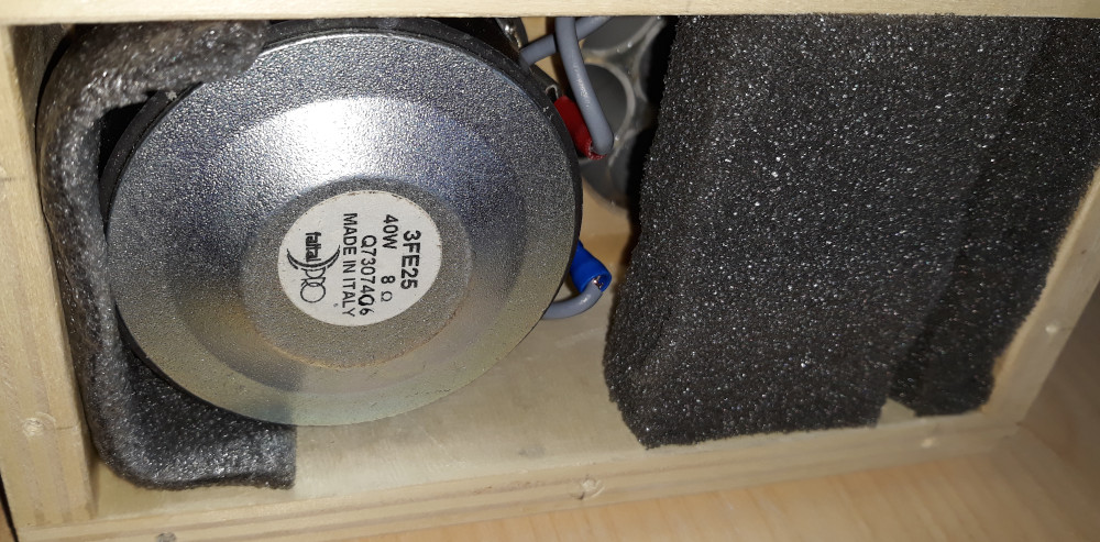
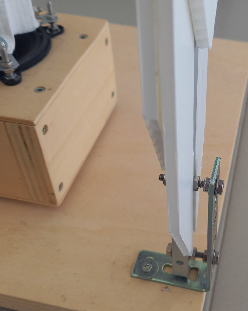
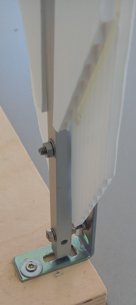
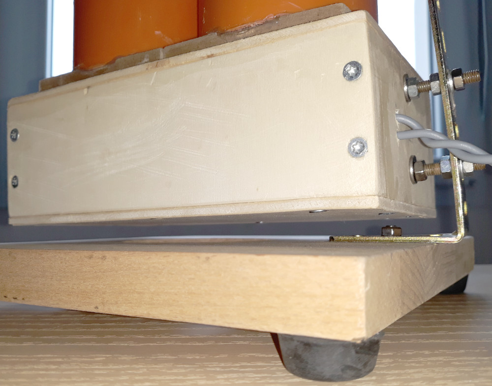
Here is a new one for me. What looks like a whizzer is not part of the woofer section. It doesn't move and forms a guide for the tweeter. I am aware of those older type large woofers with rectangular horn over the coax tweeters. This driver seems to differ a bit by trying to balance woofer cone depth and guide height by taking a flatter approach. Could this be the approach to explore for the community development? I want to investigate this approach in detail by combining an extended range subwoofer/woofer and a FR or tweeter that can go low. The donor woofer would have a large enough dust cap that can be removed to mount a custom throat that can retain the higher frequency driver and the woofer vent large enough to run a line to a volume mounted behind the woofer magnet. If we can find the right donor woofer and HF driver, then we can place a custom foam overlay on the woofer cone to change its dish to a flatter one while matching a waveguide to the HF unit that will ensure zero interference with the woofer cone surface. I have a feeling this can work with enough development effort. The overlay can be made easily with DIY jigs, and I am able to demonstrate that. At some point I will attach some FreeCAD files that we can pull and tweak for the guide and HF throat, line and volume and this can be printed at home

For anyone thinking of IP type issues here, let's be fair, if anyone can take any ideas from the thread and commercialise it, well make it good enough to be worth my while and I will buy them from you!

1712656805532.png

Monster Power Power Conditioner Buzzing

Hi everyone,

I have a 'Monster Power HDP1750G+ Powercenter' power conditioner which is making a loud buzzing noise.

The unit seems to be working fine other than the buzzing noise.

When you plug it in there is no noise. You turn the power switch on, and there is a low volume buzzing noise from the left hand side of the unit. Then after about 10 seconds a relay kicks in and a loud buzzing noise comes from the right hand side of the unit.

I have contacted Monster and they have told me that this noise is the surge protection circuitry kicking in and that I should dispose of the unit.
They have also advise there are no schematics available for this unit.

I have opened the unit up and everything looks clean and healthy (nothing looks blown or damaged).

The buzzing seems to be coming from the section with the varistors, chokes, caps, and relays (circled in the picture)

Has anyone come across this problem with a Monster power condition before?

I am suspecting it's the varistors which is making the noise and needs changing? Am I correct in my assumption?
If so, is it something I should do? Or is it time to dispose of the unit?

Thanks

Attachments

  • Inked2021-10-06 14.36.19_LI.jpg
    Inked2021-10-06 14.36.19_LI.jpg
    988.1 KB · Views: 468

Seeking: Budget LCR meter to measure unknown Crossover (Tangent Acoustics RS2)

Objective: I am looking to a) measure the components on the 2-way crossover of the Tangent Acoustic RS2 speakers I have and b) duplicate the crossover to build a new speaker with the same drivers (T27/ Audax HD20 B25J).

Current Plan:

a) Map out the circuit with a continuity tester
b) Identify bands on resistors/markings on Caps for ratings
c) Use an LCR meter to measure and confirm labled vs actual
d) Establish the delta and list components that need to be replaced in the old crossover.
e) Purchase components to re-store old cross over + build a new crossover.
f) Learn how to solder 😀 and build it out.

Current Roadblock: Purchasing a LCR meter that allows me to measure all components. Hence this thread.

I am considering the Tenma 72-10465 and the EXTECH LCR200.

Reason: Budget, and I see the EXTECH supports 5 different test frequencies vs the 1 on the Tenma. I am hoping for accurate readings on the 3 inductors since they can be hard to measure (is my understanding)/can influence the sound heavily if not duplicated correctly.

Seeking feedback from folks and their experiences with rebuilding/duplicating a crossover. Thank you!

Supply voltage for THAT1253 series receiver

Hello
Looking to test drive a component..
Wondering if real world conditions for the THAT1253 device will work with my present power supply..
The device has a listed minimum VCC-VEE of 7V, and I have +-5 for 10V, and I am curious if this is an adequate margin.
Not in the mood to redesign my power supply if not needed.
Preceeding single ended signal voltage is 2.1Vrms and differential is 4.2Vrms from the DAC that I have.

Thanks for any advice
S

Total Eclipse...

We live in the Dallas-Fort Worth area, and at 1:40 PM local time (about 30 minutes ago as of this writing) experienced a total eclipse, basically unobstructed for 3-4 minutes. It was really cool watching the shadows on the ground that had filtered through the tree leaves turn into crescents beforehand--something we've seen a few times before with partial eclipses.

What made this really different is that the sun was completely blocked out (making it easy to look directly at the moon/sun without any optical filters at all), to the point that street lights in our residential area turned on--like a very deep twilight. The way that the lights came down, though, was the coolest part. It appeared like someone turned down the lights using a dimmer light switch--twice--but spread over 1-to-2 seconds each time, and both times spread a few seconds apart.

If I hadn't been there, I would have thought that it was hyperbole--but it's not.

So how rare was this event? Well the last time it happened here was apparently 1873...and the next time is said to be 2317.

That's pretty rare.

JMTC.

Chris
  • Like
Reactions: stv

Completed Balanced Iron Pre

Hello,

I built a second balanced Iron Pre with a remote control volume control, so I am selling the first build. It sounds great!
  • Two balanced inputs and three RCA inputs.
  • One balanced and one RCA output.
  • Dual high quality stepped attenuator volume controls.
  • Hifi2000 chassis
  • Shielded cable to and from VCs, balanced inputs and balanced outputs.
  • Completely noise free at full volume on every input.
Total cost to build was right about $900.00. Will sell for $700.00 plus shipping and Paypal fees (if you don't use Friends and Family).
Shipping to U.S.A. addresses only (possibly Canada but you may get shafted on customs).

Note, I forgot to dust off the top cover for pictures, but it is in great shape. I didn't have it powered up when taking a picture of the front. The LEDs on the selector switch are blue and not blindingly bright.

IronPreFront.jpg


IronPreBack.jpg


IronPreBalanced.jpg


Frequency response at 96kHz
fr.png


THD plus noise at full volume:
thd.png


Stereo crosstalk:
cross.png


Thanks for looking.

Alan

Ultra Analog, The Ghost Company

When a person purchases a piece of equipment, one never knows what the future holds. What are the odds the company you purchased the $2,600.00 DAC from would go out of business, and the people they bought the major components for that piece go out of business as well? It happened to me. I joined this group to see if there is a person out there with the technical expertise to say, let me take this challenge on!

I purchased an outstanding piece of equipment several years ago from "the old" PS Audio Company, not to be confused with the NEW PS Audio. The old PS Audio let a company named Ultra Analog build a wonderful product called the Ultra Link II Digital to Analog converter, mine even has the HDCD chip to top this DAC off. The two most important parts in this DAC were the internal Ultra Analog DAC and the Ultra Analog AES 21 Digital Interface or input receiver.

How does the story end, the AES 21 Digital Interface (receiver) goes out, and it's parts are potted in a nice block of epoxy, where no one can know Ultra Analog's secret parts! The old PS Audio goes out of business and Ultra Analog also goes out of business, and then the owner of Ultra Analog suddenly dies. and takes the schematics to the grave. Both companies dead, and no more parts. Is there an audio explorer out there that can bring this beautiful piece of equipment BACK TO LIFE! The challenge is on the table, I would appreciate hearing from that very special engineering mind, (LiteJazz53@yahoo.com)

LiteJazz53

What material should the Air Core Inductor Coil be made of

Hello friends

I opened a topic last week
https://www.diyaudio.com/community/...-and-tweeter-in-parallel.411688/#post-7659330

I decided to make a 4500 khz crossover. but first I need to make an air core inductor coil. in the link above a friend explained how to do this. my question is what material should the air core inductor coil be made of. copper aluminum tin silver. i have aluminum wire.

I will make a multilayer coil. I made a tool for it on a lathe​

Preventing damage to tweeter when connecting midrange and tweeter in parallel

Hi guys
I bought a car audio system from abroad. But I have a problem. I need to connect the midrange and tweeter in parallel. I use the crossover mode on the amplifier with the hpf option. This option can cut frequencies in the range of 32-2000 Hz. (I will add photos)
The problem is that I use this setting at the extreme end (2000hz) to avoid damaging the tweeter, which causes the sounds to sound very high-pitched. Can I reduce this frequency setting if I connect a capacitor in series with the tweeter?
I have a 3.35uF capacitor.

midrange; 4 ohm 95-10khz tweeter; 4 ohm 2khz-20khz, fs 2000 , dc resistance 3.2 ohm
Image 2024-04-16 at 19.24.25.jpeg

Puzzler: Strange high-frequency noise on power-up only; lasts a few seconds

I have a very strange problem indeed.

I built Kevin Gilmore's CFA3 amplifier, the I added Kevin Gilmore's GRLV linear supply to power it.

When I power the amp from a cold start, a high-frequency, almost whistle-like sound shows up on the output. It las a few seconds (longer if it's cold, less if it's hot) and then goes away. While that sound is heard, I can make it go away by touching the 4-pin XLR output socket.
Once the amp has been running a while, I can power it off, wait a couple of minutes, and power it back up with no noise of any kind.

I think this strange noise didn't come with the previous power supply.

So, quite a few clues, but none of it makes sense to me.

Any wizard can school me on that one?

I suspected oscillation, transformer ringing, and various other things, but I can't convince myself they could be valid reasons.

Sica 1.1" Dome Tweeter (Z009160) - good candidate for waveguide based 2-way?

Sica Z009160 is the driver in question ~69 EUR. It can take a low crossover point (1.5kHz recommended minimum) which is handy. I would imagine the narrowing at higher frequencies due to the larger than average dome diameter would pair well with a waveguide. (not shown, just an assumption) Giving a more even power response through the upper mids and treble.
Anyone used this tweeter before? or more generally used a large >1inch tweeter? Does the typical narrowing in the top octave due to diameter create any sound quality concerns?

1712689736842.png

Michel Gyrodec

I was just rooting around on the web today and noticed that the Gyrodec prices have gone through the roof. A basic Gyrodec with a bog standard Rega sourced arm and an MM cart sells for £3499 now but most are at £4500. Thats up £2000 from where they were 5 or 6 yrs ago. What is going on? I just wonder if Michel have woken up to the fact the Gyrodec was under-priced?

1713615767096.png

Canary Daart headphone amp/ DAC hum

Hi. I have a Canary Daart DAC and there is a hum like sound and music not playing well. When I checked 5173g regulator i see that it is extremely hot. When I push it with a pen, hum is reduced but bottom of the pen melted because chip is too hot. I couldn't find this chip in my country. Can I use equalivent chip or maybe a better one? Coiltronics coil is also buzzing.I am a bit disappointed because it was an expensive dac and I did not use it much. 5khz square wave also almost same as my cheaper Muse DAC which I added in pictures ( I made a mod and changed the power supply Panasonic FC 1800uf capacitor with 2x 1000uf Nichicon muse capacitor but I do not think it caused a problem) I was happy with the sound before it malfunctioned) Regards

Attachments

  • 20240409_181647.jpg
    20240409_181647.jpg
    339.8 KB · Views: 68
  • 20240409_172841.jpg
    20240409_172841.jpg
    338.7 KB · Views: 74
  • IMG-20240409-WA0019.jpeg
    IMG-20240409-WA0019.jpeg
    378.6 KB · Views: 75
  • 20240409_172318.jpg
    20240409_172318.jpg
    408.4 KB · Views: 71
  • 20240409_172200.jpg
    20240409_172200.jpg
    413.5 KB · Views: 93
  • 20240409_165940.jpg
    20240409_165940.jpg
    301.5 KB · Views: 70
  • 20240409_165324.jpg
    20240409_165324.jpg
    299.1 KB · Views: 64

CREST Catastrophe

Hi Folks. The latest drama with a Crest CA-18 that I have attempted to tame for home theatre use; exploding main filter caps. The caps actually leaked and the fluid was absorbed by an insulating fibre board causing a short with spactacular results. I brought this problem on myself with the replacement of the cooling fans with slower, lower CFM units. I also installed a resistor in series with the fans. The amp heat sinks never really got hot but the caps are boxed in and glued together, shielding them from the limited air circulation.

My goal is to modify the fan control circuit to run slower at 75 degrees F and faster at 95 F

Attachments

  • DSCN2935.JPG
    DSCN2935.JPG
    475.7 KB · Views: 362
  • DSCN2939.JPG
    DSCN2939.JPG
    455.6 KB · Views: 363

Any way to increase gain?

I built the ANK L3 Phono amp. Actually its a clone but loaded with premium parts. It works great. No noise and sounds good but I need more gain. Is there anything I can do to this circuit to increase the gain a little? I am running a DV20X2 High output cart and it requires I turn my amp up to 3/4-7/8 volume to get listening levels where I like them. My previous phono amp had adjustable gain and was a fair bit louder. I have it loaded with all factory recommended values. Is there any resistor changes or something similiar I can change to get more gain out of it?
L3 phono.jpg
  • Like
Reactions: TonyTecson

Krell KAV500i problems

Hello,

I have an unfortunately defective Krell KAV500i. All transistors in the output of one channel were broken. I have now replaced it, but it plays totally distorted at low volume.

Strangely enough, I have this distortion on both channels. When I turn up the volume the distortion disappears.
I can't even imagine that now.

Attached are the two circuit diagrams that I found.

Attachments

MDD Multi Delays Diffraction (Multi TL, omnidirectional, single drive, ...)

MDD Multi Delays Diffraction (version 2024.04)

The characteristics of the listening environment are very important for the quality of playback. With MDD technology, part of the energy emitted by the speakers is used to generate secondary sound fronts, the spherical fronts generated by diffraction are coherent, delayed and optimize interaction with the room. The emotions produced by listening to recorded music can also be obtained without treating the room acoustically and with economical broadband speakers. MDD Multi Delays Diffraction. The multiple emissions simulate three-dimensional sound sources, the delays optimize listening in environments that are not acoustically treated, the diffraction makes the speaker omnidirectional at all frequencies.

Acoustic loads are made with multiple waveguides. Each single waveguide adds secondary, delayed and coherent sound fronts to all sounds even if the recording was made with microphones positioned in non-ideal points. The primary and secondary emissions are reflected by the environment and reach the listener who perceives them as compatible with a three-dimensional source present in the room. Omnidirectional emission in a reflective environment increases the amount of waves reflected from the listening room. When the reflections of the recording room are reproduced due to the Haas effect, the brain perceives them as a continuation of the previous signals. The succession: primary wave, coherent and delayed secondary waves, reflections from the listening room, reflections from the recording room become a single sound for the brain that is easier to interpret and pleasant to listen to. It decreases the time needed for memory to decode sounds and increases the time available for imagination. Playback is similar to listening to instruments live in your room. It's not the most faithful conditions to the original recording but it can be a lot of fun. The listening area is large and you can better follow the music from every point of the room.

I have reorganized the material on MDD projects, there are three common components:
1 - mddOmni (3D effect, anti Haas effect, omnidirectional acoustic diffractor, sound recognition),
2 - mddTL (neutral cabinet, logarithmic sum),
3 - subsonic resonance support (asymmetric base).

mddOmni

a2r01.jpg

3hB612.jpg

The mddOmni front acoustic load has sets of waveguides of increasing length positioned in front of the driver. A part of the acoustic energy emitted by the driver cone enters each guide. The same energy is re-emitted by acoustic diffraction, in different positions, with increasing delays, with spherical wave fronts and consistent with the direct emission of the driver. In the latest prototypes the guides are open on both sides with L/2 resonances. The driver's directional output becomes omnidirectional.

mddTL

3fe25-933.jpg

3fe25-935.jpg

3fe25-934.jpg

The mddTL rear acoustic load has multiple waveguides of increasing length attached to a compression chamber, it is a set of transmission lines with L/4 and L/2 resonant frequencies. At low frequencies the mddTL acoustic load is neutral with respect to the drivers and the listening environment.

subsonic resonance support with asymmetric base

a2b09.jpg

a2b10.jpg

3fe25-b907.jpg

a2bsup.jpg

Subsonic resonance mount acoustically isolates the speaker from the floor in the audio band, improves reproduction detail. The asymmetric shape reduces the triggering of spurious vibrations.

3D effect

a2_punto_ascolto.jpg

Multiple emissions simulate three-dimensional sound sources. An instrument emits sounds from multiple points at the same time, the multiple emission points simulate the instrument in 3D. MDD speakers are not able to recreate the exact size of the original instrument but listening improves compared to the reproduction of a point source.

anti Haas effect

a2_1k.jpg

a2_step_response_left.jpg


The Haas effect (precedence) occurs when two identical sounds arrive at the ear in succession. With delays greater than 5 milliseconds with simple sounds (clicks) the ear perceives distinct sounds. With more complex sounds the time increases to 40 milliseconds. The emission points of the mddOmni and mddTL acoustic loads are located at increasing distances from the driver and the secondary sound fronts have delays of between 1 and 10 milliseconds compared to the primary emission of the driver. The succession of sound fronts prevents the activation of the Haas effect, a single event cannot be perceived as two distinct sounds.

omnidirectional acoustic diffractor

Acoustic diffraction makes the speaker omnidirectional at all frequencies. According to Huygens' principle, every point on a sound wave front is a secondary source of spherical waves. The end of the waveguides of the mddOmni and mddTL acoustic loads are omnidirectional emission points of a linear acoustic diffractor across the entire audio spectrum.

neutral cabinet

MDD3FE25d_FR_BL7-1ND__Z_FL_D_BL_ND_b.jpg

In standard TL speakers a waveguide is used as an acoustic screen to reproduce low frequencies. In general, the longer the guide, the greater the extension of the low frequencies, but the problem of interaction with the response of the loudspeaker and nearby walls must be resolved. The design of the mddTL rear acoustic load is much simpler. Multiple waveguides are used with the lengths calculated with the same formula that determines the frequencies of musical notes, the resonances of the waveguides are distributed homogeneously over an octave. With logarithmic series lengths the speaker is neutral with respect to the frequency response of the driver and the listening environment.

logarithmic sum

MDD3FE25d_FR_FL7-1ND__Z_FL_ND_BL_D_b.jpg

80dB + 80dB = 83dB,
80dB+60dB~80dB,
60dB + 60dB = 63dB.

other links

psychoacoustics

asymmetric base

CL08A2

  • Like
Reactions: pelanj

Yamaha CA-V2 relay problem

Hi

I have a problem with the relay in this model and I don't know what could be the cause, but let's get to the point.

The amplifier starts up correctly and theoretically everything is OK, but within the first 10 minutes of operation the relay turns off and turns on again after a few seconds. This happens 2-4 times within 10 minutes and then everything is fine. The fault occurs mainly when the amplifier is not used for several hours, but this is not the rule. I corrected all the cold solder joints, and there were a lot of them. I checked the capacitors in the relay activation circuit and everything is OK. No DC voltage at the output before the relay. At the points marked with a red arrow there is approximately -12V, which holds the relay coil.


Sometimes the relay turns off and on when I stop the music.

The photo shows that someone has already repaired this amplifier. He replaced power transistors and emitter resistors. He replaced the fuse resistors with ordinary resistors connected in parallel. 😒

I'm asking for tips, because I have no idea where to look for the cause. 😒
🙁

Attachments

Balanced Preamp Advice

I built a Chassis that has an Aleph J in it right now but I built it with the idea that I would change out various amplifiers and I want to build a preamp to provide multiple inputs and volume control. Ideally, I would like to be able to bring both balanced and RCA inputs into it and provide a balance out to the amplifier. I have a DAC with a balanced output, a phono pre-amp with RCA, and CD with RCA. I was thinking of building a Balanced Output Son of Zen Pre (BOSOZ) amp and I hope to design a board for input control and maybe individual attenuation on it for each input if needed to get volume matching. If I get fancy I would design it to be selectable for XLR output to the Aleph or RCA output to my Tube amp or whatever. I don't think I need much gain but it seems nice to have some as an option. I have an FE 2022 connected which gives me 10 dB right now and I haven't needed more.

I would also need something for the output side for volume control. I was thinking of a relay-controlled step attenuator board for volume (does anyone have a design or PCB?) I don't need much gain in for the amps I have but it seems nice to have for the future. I like the BOSOZ because I have about 1/2 to 2/3s of the components and it seems simple.

My question is this a good solution or are there better options I should consider? Is the BOSOZ a good-sounding pre-amp? (seems like a silly question since Papa designed it)

Question about mounting UcD amp modules

I bought some remarkably inexpensive amp modules from China on ebay.
They are UcD based and compatible with the Hypex 400A400 power supplies I have.
Unlike the OEM modules they come on robust metal plates, much like the real Hypex modules. They aren't direct clones though - they have single ended inputs which is handy for the rip and replace I'm looking at. As well as being cheap.

What's the preferred way to mount things like this? There are a couple of holes in the bottoms of the plates that I could perhaps use by drilling the bottom of the amp case I'm reusing, but I'm wondering whether double-sided thermal transfer tape would work OK, and/or heatsink glue - and just glue them to the base of the amplifier.

There's no instructions, but the pins on the modules are labelled. If they don't work out, I'll get some real Hypex modules but I don't think I can get 6 channels in the case I have, which is what I'd like to do. The modules I bought are a mix of 1-channel and 2-channel, and while the case had 8 off UcD250OEMs, I can fit 6 channels in like this..

New version of my tonearm phono preamp

This is sort of a continuation of previous thread https://www.diyaudio.com/community/...er-light-phono-amp-inside-the-tonearm.268400/
that one diverged rather hence new thread.

The new version features a lower noise front end, but is a bit more cramped as a result.

P1050755.JPG

P1050754.JPG


There is a NE5534A RIAA stage at the left, one on each side for L+R.

The board is 8mm wide and 95mm long.


P1050756.JPG


Then two 2nd-order Sallen Key stages implementing a 4th-order Butterworth high-pass "rumble" filter, detail on one stage (two channels):
P1050757.JPG


The opamp here is NE5532A dual.

The response to 5mV rms 1kHz input, both channels:

new-ne5534a-tonearm-preamp2.png


No special precautions against mains hum, other than short leads to the QA403 analyzer, and the high freq hash is probably from laptop or LED lighting or both. Power was +/-9V from batteries, the QA403 is galvanically isolated which no doubt helps.

And the response, weighted with inverse RIAA:

new-ne5534a-tonearm-preamp-resp-riaa.png


The rumble filter slope is clear, about 14dB down at 10Hz and ~36dB down at 5Hz.

Schematic:
Screenshot 2024-04-20 at 09.30.29.png


Its a little hard to read, but the RIAA feedback network is 3.3nF || 22k and 12nF || 270k, with 330R to ground. Caps are PPS and resistors thin-film, 0805 and 1206 size

Attachments

  • P1050756.JPG
    P1050756.JPG
    31.7 KB · Views: 88
  • Screenshot 2024-04-20 at 09.28.23.png
    Screenshot 2024-04-20 at 09.28.23.png
    100.3 KB · Views: 79

For Sale Scanspeak D3004/6640, D2904/7100, 18M/8631

Scanspeak 18M/8631T00 pair
Used, good condition, $250 US

Located in Australia, will ship US/worldwide.


Spanspeak D2904/7100 pair. **SOLD


Scanspeak D3004/6640 pair. **SOLD

Attachments

  • 20240211_144417.jpg
    20240211_144417.jpg
    443.3 KB · Views: 94
  • 20240211_144424.jpg
    20240211_144424.jpg
    677.1 KB · Views: 87
  • 20240211_144421.jpg
    20240211_144421.jpg
    767.6 KB · Views: 95
  • 20240211_134358.jpg
    20240211_134358.jpg
    346.5 KB · Views: 94
  • 20240211_134347.jpg
    20240211_134347.jpg
    313.8 KB · Views: 103

Has anyone been to one of these Hi-Fi listening restaurants?

Saw this today. Quoted here is a small section of the article from the Wall Street Journal:

At These Restaurants, Good Sound Is Just as Important as Good Food​

A new wave of listening bars and restaurants pair high-quality food and drink with stunning high-fidelity audio​


It wasn’t the song (something by Cake) or the volume (modest), but the clarity and richness of the sound emanating from the speakers nestled among the albums and whiskey bottles behind the bar.

“It was three dimensional,” Brock recalled. “I couldn’t think about anything else.” Eventually, he asked about the gear the owners were using, “and by the time I was landing in Nashville I had already found the exact speakers and the exact amp.” Barely 90 days later, his speakers—vintage Tannoys used in recording sessions with the country supergroup the Highwaymen—and an assortment of powerhouse McIntosh amplifiers were wowing customers at Bar Continental, Brock’s newly re-christened restaurant in the Grand Hyatt Nashville, along with a record collection thousands strong.

End Quote

The full article is in the Arts and Culture, Food and Cooking Section at their website.

Hard for me to eat and listen seriously at the same time. If the quality of the sound is compelling, I cannot eat. Sipping wine, of course, works, but sitting still is best.

Has anyone been to one of these restaurants? What was it like?

David

For Sale Analog Behringer ECM 8000 and digital miniDSP UMIK-2 measurement mike

I have an analog Behringer ECM 8000 and digital miniDSP UMIK-2 measurement mike I no longer need.

The Behringer analog ECM 8000 has an XLR output and connects to a standard mike input with phantom power on your measurement soundcard. € 25 plus shipping.

The digital miniDSP UMIK-2 has a USB-interface and connects directly to your PC or laptop.
Supported by miniDSP with or without Dirac, and most measurement programs like REW and ARTA. € 100 plus shipping.

Contact me for a binding shipping estimate. Original box no longer available but I will pack careful and safe.

Edit: both sold.

Jan

Advice for EL84 SE PCB

Hello all. I've been quiet for a while- workshop is in the middle of a very slow remodel, and most of my gear is buried. Taking that time to plan some projects, and get parts together until I can clear off a workspace to get back to multiple in-progress PCB work (the 6v6 Salas boards, my PSU boards, among others) and resume hobby stuff. I also ordered some of my PSU mosfet filter PCBs, based on Millet's mosfet filter from his Engineer's amplifier.

A while back I designed a quick EL84 SE stereo PCB, and since I had a coupon from JLCPCB, I ordered a set to play with. I have some generic 5K SE output transformers, and plenty of Sovtek EL84, Surplus 6P14P, 6N1P, 6N2P, cleartop 6CG7/6FQ7, and a suitable power transformer that should give ~290-300 volts after smoothing. Easy peasy right?

Just to be clear, I will not be purchasing any additional tubes or transformers here. I am restricting those choices to parts on hand. I have a big enough stash that I will not be spending anything except on the chassis, most likely.

Here's the Schematic, the LED is in parallel with the spot for a resistor, in order to be somewhat universal, I'm likely using a bypassed resistor-

SENOVAL-1 (1).png


And here's some pics of the 100mm square PCB, only change is that I rounded the corners, added a capacitor across R9 for feedback compensation if needed, and ordered them in purple. The PCB allows pentode, triode, or UL connection-

SE0209top.png

SE0209bottom.png


Here's a multi-layer view of the 50mm square power supply PCB i have coming as well-
Mosfet ripple filter.png


Transformer specs (generic black chinese units, no frequency graph)-
REHOC Inductance Value: 12H
Primary DC Resistance: 315 ohm
distance of mounting holes: 72 mm
colour: black
Material: metal
Size: 60x55x50mm
Weight: .41kg
They arrived very beat up and dented, and I received a refund, in addition to that, I got to keep them. Some work to clean up the dents and some hammertone paint to cover the imperfections should make them perfect for a prototype build. Reviews on them were found that explain them to work well within the 4-5 watt power level, and they allegedly have adequate frequency response as well.

61Xg9bjfaGL._AC_SX679_.jpg


My chosen operation point for the EL84 is 5K load, 250 volts plate to cathode, and a bypassed cathode resistor, value to be determined by the choice to run either pentode or triode. Going to likely go off the datasheet values and adjust as needed for the 6P14P/EL84 that I have on hand.


So my main debate here, is what to do for the main topology.

I am currently considering the following three options for overall circuit configuration-
-Pentode output, 6N2P input, with cathode feedback to the 6N2P
-Triode connected output, 6CG7 or 6N1P input, no global feedback
-Triode connected output, 6N2P input, with cathode feedback to the 6N2P

I really like the idea of triode with global feedback, but I also really like the idea of running a 6CG7/6FQ7 front end, with the disadvantage being I will not have much headroom for lower level sources. Since the output stage only needs like ~8 volts bias worst case, I should have no issues running the lower mu front end. I have many 6FQ7 cleartops onhand, and less 6N2P onhand. The lower power output of triode mode is no trouble, as this amplifier will be run near field with DIY speakers of reasonable efficiency. I'm not terribly fond of triode/pentode switching, so It will likely stay in whichever configuration I build it into unless there is a compelling reason to change it up later.

Any input?

Almost everything I build is pentode connected with global feedback. Rarely do I ever go for something run "wide open" so I feel like I'm cheating going for zero global feedback. Last EL84 triode build I did was push pull with global feedback as well.

Thanks for taking a look!
  • Like
Reactions: Dieter Geissel

Is this solution acceptable?

I'm looking to modify my beloved Braun LS200 speakers. In fact, they're nice speakers but I'm curious to know. The LS200 are 3-way system with 4 drivers including 2 twin woofers. I've played with them by unplugging other drivers and listen to a single driver. I found that the woofers not only play bass but also midrange. I, then, tried using graphic equalizer and discovered that eliminating midrange from the woofers satisfied me. I tried tweaking passive crossovers many times to suit the setting on EQ, but, none of them archived the target.

However, I have the last method. I found the schematic of B&W Matrix 3 series 2 which are 2.5-way system. It sparked an idea. Attached is the low-pass filter circuit of the B&W.

BW Matrix 3 S2.png


Regarding L2 (8 mH) on the B&W's schematic, I think to add a large inductor to one of the LS200's woofers, red circle in the picture.

LS200 mod.png


The objective is to limit the midrange from one woofer. On the other hand, my LS200 would be converted to 3.5-way system. Anyway, I have 5.6, 6.6 and 8.2 mH inductors in my hand. I'm thinking to try them all. But, I'm not sure whether it will create any problems. Please advice if there're problems occur; such as too low impedance, distortion created, or low-pass filter modification needed, etc. If there're any, then, I will stop this project. But if it's fine, I will go on.

Open-source USB interface: Audio Widget

Announcement: Audio Widget project

The Audio Widget project is open-source code and schematics for
USB based digital audio. It has functional firmware and software. And
it sounds good!

Cool? You bet! Here you can get started with USB audio without
worrying too much about the USB part of things.

Or you can contribute to a great open-source coding project. The
most important contribution we could need right now is coders for
USB Audio Class 2 drivers on Windows. But other efforts are needed
too. See below.

The code is written in C for the Atmel AT32UC3A3256 32-bit MCU. It
supports USB Audio Class 1.0 and 2.0 (UAC2). On Windows / UAC1 it
works with 24/44.1 and 24/48 with sample skip/insert. Asynchronous
USB is in progress, and we could use your help.

On Linux (>2.6.37) and OS X, using asynchronous USB, it also
supports 24/88.2, 24/96, 24/176.4 and 24/192. The open-source
firmware is in a git repository. It can be selectively compiled to run
on the three different boards. The firmware includes several UI and
display options.

There are three hardware options. The hardware is in a beta state. It
plays music very well, but there is still tweak potential.


1) A stand-alone USB-DAC with stereo audio playback functions only.
This board uses the ES9022 DAC chip. Contact
george.boudreau@YoyodyneConsulting.ca for info on how to obtain
one. More information on the this and other audio designs visit
Yoyodyne Consulting/Audio Hardware

2) USB-I2S module + Analog Board. The module has all the pinouts you
need for digital audio, GPIO, I2C, SPI, LCD display and UART debug.
The module uses 2.0mm pitch pin rows. The Analog Board uses the
module to do stereo playback with an ES9022 DAC and low-noise
VBUS-LDO based power. AB-1 is a straightforward design to begin with,
and if you're into analog tweaking we challenge you to make your own
versions! Schematics and BOM are on
Downloads - sdr-widget - Audio and Control Interface for Amateur Radio SDR and Audiophile USB-DAC - Google Project Hosting.
Go to Q N K T C USB-I2S Module and Analog Board 1 for more information. Contact
borge.strand@gmail.com to obtain a kit.

3) SDR-Widget Beta 2.0. This is the original fork of the project,
open-source HAM radio. The hardware supports both playback and
record. Contact george.boudreau@YoyodyneConsultingl.com for info
on how to obtain one. Visit
Yoyodyne Consulting/SDR-Widget
for more information of pricing and availability.

For more information, go to sdr-widget - Audio and Control Interface for Amateur Radio SDR and Audiophile USB-DAC - Google Project Hosting
and
https://groups.google.com/group/audio-widget?hl=en
This announcement is cross-posted. Please join the mailing lists of
both SDR-Widget and Audio-Widget to continue the discussion there.

SDR-Widget is the original branch, where most of the firmware
discussions take place.

Feel like contributing? We'd always like to see more hands. There's
quite a few tasks planned:

- Firmware for Asynchronous UAC1 / Windows for 44.1 and 48ksps.

- Analog tweaks. Ideas are welcome for PSU, DAC, IVC, preamp etc.
Feel free to make suggestions, or even better, your own Analog
Board for the USB-I2S module.

- Windows open-source drivers for USB Audio Class 2.0. This
protocol is supported in Linux and OS X kernels, but not yet
in Windows.

- Adding more IO control to the firmware


Cheers,
Børge

Low voltage high current rectification

Although there could be strong opinions about tube vs. solid state rectification, tubes objectively have no forward voltage cutoff, which causes ringing in the resonant tank of power transformer's leakage inductance and distributed capacitance. The ringing can be snubbed with an RC snubber, but the first few oscillations will still remain. Moreover, hard cutoff of SS rectifiers at forward voltage (about 0.7 V for regular Si diodes and 0.3-0.4 V for Schottky diodes) creates broad spectrum high frequency noise that is better be avoided.

The problem is especially important with low voltages such as those needed to power DC filaments of such tubes as 26, 45, 2A3, etc. With silicon diodes, the cutoff voltage may be as high as 30-50% of the rectifier output. And it goes without saying that noise is the last thing one would want in a filament supply.

I believe I found the solution to this problem: germanium rectifiers. These have forward voltages of 0.3-0.35 V, but that's not their main advantage. Importantly, their behavior in the low voltage-low current area is similar to that of tube rectifiers. They don't have the hard forward voltage cutoff. Here is a low voltage static plot for the Russian D305 Ge rectifier that I experimentally derived. D305 is a 10 A 50 V diode.

Attachments

  • D305.jpg
    D305.jpg
    11.3 KB · Views: 125
  • 20240311_235701 (1).jpg
    20240311_235701 (1).jpg
    230.2 KB · Views: 118
  • Like
Reactions: Fei

PCB design using TLV320DAC3203

I have designed a PCB for adding an audio output to a Flipper Zero device after verifying that an I2S interface was available through the GPIO headers. This is my first post after hearing about the forums for years.

I am a beginner to circuit design so there may be a lot to fix. Any ideas to improve the design will be appreciated.

PCB design, BOM and schematic are attached.

Attachments

Originality of the LM3886TF

I bought two units of the LM3886TF chip here in Brazil for around $32.00 each.
It was very difficult to find...
I've seen several photos of original chips on this site, these mine look very much like originals, they are up to all datasheet standards.
Any thoughts on its appearance and originality?

Attachments

  • 20230511_131129.jpg
    20230511_131129.jpg
    277.1 KB · Views: 289
  • 20230511_131523.jpg
    20230511_131523.jpg
    354.3 KB · Views: 275
  • 20230511_131646.jpg
    20230511_131646.jpg
    303.9 KB · Views: 268
  • 20230511_131716.jpg
    20230511_131716.jpg
    323.2 KB · Views: 238
  • 20230511_131811.jpg
    20230511_131811.jpg
    343.7 KB · Views: 266

Crown Powerline 2 Oscillation

A Crown Powerline 2 (earlier version) came to me with a shorted output and a few other smoked components, Specifically, the Q113 output was shorted, Q110 was blown apart, and R129 was burned up. I replaced Q113 and Q108 with new MJ15015 outputs, installed a 2N3906 for the 2N4125 at Q110, and replaced R129. No other components tested as faulty.

The amp powered up ok with a DBT, and also directly to the mains. However, as soon as I attached my 8 ohm dummy load, I'm seeing pretty significant oscillation in the left channel. I assume that I may be seeing the underlying cause of the original damage. I need more experience solving oscillation issues, so it looks like I have my opportunity. I've attached a portion of the schematic showing the left channel amplifier section. Any direction as to where to start would be appreciated.

Schematic Section.jpg

Had Your Hip Resurfaced?

This is what my surgeon is proposing for me to deal with osteoarthritis. He said that though I'm 67 my bone density is high, I'm physically very active, and that resurfacing would be better than a hip replacement. The risks of fracture and dislocation are significantly lower than with replacement, there's a much better chance of returning to full activity after the operation though revision rates are slightly higher. If it all goes pear shaped I can have a replacement anyway.

But has anyone here had a hip resurfaced? What's been your post op experience?

My first post-op report, after three weeks, after eight weeks.

Just how rare is my Akai DC-34 dust cover?

I’ve picked up a CS-34D cassette deck, which came with a matching dust cover. I cannot find a single image, anywhere, of another deck with this cover. I found an advert listing it as an option, but that’s it. I’m thinking it might be worth more than the deck itself! It’s the cover lower right. Has anyone else seen one?

Thanks,

Mat

Attachments

  • BB2B38AA-AF10-45BF-83C3-954F9A4EE4EA.jpeg
    BB2B38AA-AF10-45BF-83C3-954F9A4EE4EA.jpeg
    298.1 KB · Views: 91

IRS20957 S problem after repair

Good morning everyone ! I'm repairing a RCF ART -710A MK2 ! In the treble amplification part it uses a class D module and has IRFB4229 as final mosfet and IRS20955 as driver which I replaced with IRS20957!
Now I have this problem! When turned on everything seems to work but after a few seconds checking the waveform on the gates of the mosfets I have an inaccurate square wave of different amplitude, to then turn off as if the driver went into protection!Is it possible that between the 2 drivers I have to replace resistive values or does it require different values for example on the OCSET and VREF pins?

Attachments

  • 20230216_094705.jpg
    20230216_094705.jpg
    515.7 KB · Views: 219

Greetings from Illinois

Hello All

Former audio enthusiast turned recent convert after reading about the BBC LS 3/5a (Yes, i've been living under a rock for 40+ years).

Curiousity got the better of me, and I dabbled around and got lucky with a pair of Tangent RS2s. The sound is impressive and the staging even more so. Downright unbelievable how good they sound for the age.

Other hobbies? Cars, AFOL (Adult fan of Lego), love geeking out on PC hardware.

Thank you for the inclusion. Hope to share and learn more!

Cheers
  • Like
Reactions: 6L6

  • Locked
Help wanted: bought second-hand DIY DAC, delivered in poor condition

I'd be interested to get some thoughts and opinions about the following issue:

I bought a second-hand DIY DAC from a member here on diyAudio. The DAC was advertised here in the Swap Meet, with photos that showed an acceptable build. The seller also posted about his build in a specific thread about this DAC design here on diyAudio. Once the DAC was delivered, the box looked fine and did not show any signs of bad handling. The seller also included some tube (bought separately), which were all in one piece. There is no reason to assume that the box was treated badly during transport.

However, the DAC itself almost fell apart when I took it out of the box. Most screws were loose, and some screws already fell out. I agreed with the seller that I should open the chassis and look inside. The mains transformer was loose and was dangling freely in the chassis. Some of the electronics boards were also loose, and some parts had fallen off (for example, the crystals/oscillators from the USB/I2S board were out with bent legs). It's hard to say if this is just a matter of straightening things and tightening the screws, or if there is some serious damage done to the electronics / boards / parts (e.g., due to the dangling mains transformer).

I'd like to try and rescue this thing, because I am actually a fan of this DAC design. However, I am worried this might turn out to be a black hole.

I asked the seller about his view, and he seems to argue that the loose/lost screws are due to poor handling during transport. I can't be sure, but the box did not show any such signs, and the tubes were all intact, so my gut feeling is the handling was not the real problem.

I asked the seller for a partial refund to make up for my time to repair the DAC, and for my potential expenses for spare parts and replacements. He did not respond positively to this.

I am not quite sure where to go from here. What are your thoughts? What would you do?

Dipping my toe in SMD-realms… parts recommendation (please?)

Hi all
I started a little adventure: I‘ll try to make a little crossfeed „network“ according to Jan Meiers proposition… as this is a rather simple thing, I thought this could be ideal to try myself in smd.
But I‘m very unsure about what capacitors to use there? I mean, it’s caps in the very signal-path, which smd-caps are good/best to use <duck>soundwise</duck>
Thank you

Nutube preamp question

Greetings All,
My first post here.
I am building the Nutube preamp kit and may have a packaging error.

I have begun the assembly of my preamp kit and on confirming the parts selection to the instruction sheet document I may have found a discrepancy.

The write up states that the jfets Q1 and Q2 are different and packaged accordingly.
However I have found that while the Q1 package contained 4, FKH35 J113 fets, the Q2 package contained 2, of FKH35 and 2, of WH44 J113 fets.

This raised a red flag for me and I would like some guidance on whether this is a packaging error or is there more detail needed on how to populate the PCB correctly?

All of their respective bias resistors checked out consistent at 149 ohms.

No response from the store at this time after asking about a week back.

Thanks for your guidance.

C-Audio SR707 DC offset issue

Hi all. Got a C Audio SR707 giving some trouble. Problem is DC offset on both channels. One measures 20mV approx and the other measures 40mV approx. Amplifier comes on but does not trigger protect. (I believe that triggers at 1v)

The PNP long tailed pairs have 2sa872 installed and not 1085s as schematic. (Not sure if this is a factory component change ). I tried changing out one of the pairs to a matched Hfe pair (sorry can't remember what transistors I used at the time ) but that made the DC offset even worse at 240mV!... So I put back the 2sa872. Checked current mirrors all fine too. Changed out the 24k resistors on both boards and no change. Not sure where else to look.

Attachments

Tweeter / full range question

i have lowther DX4 speakers driven by 2 x 300b mono PSE amps, and sbacoustics sb34 subwoofers (sealed in same cabinet), driven by 2 x icepower 300 AS1, both through active low and high pass filters crossed at 140Hz.

They sound pretty good but i plan to add a pair of tweeters and i am looking for recommendations and advice.

I was considering these from Fountek NeoCD3.5H

I initially plan to use a basic passive high pass filter on the tweeter, (2.2mf cap + 0.15mH coil), to pass at around 10khz, i dont think this will be ideal because the Lowthers have quite a steep rise from 1.5k all the way to around 10k so this will remain, in the future i plan to modify the active filter to include a band pass for the Lowthers, with the low pass fixed at around 2k, and the high pass on the tweeter also set at 2k, (the Founteks are virtually flat all the way from 1.5k to 30k), in theory this would flatten everything nicely (i'm hoping).

The sensitivity of both drivers seem to match quite well at 96dB, so im hoping that using the passive high pass filter initially will be OK until i can get round to modifying the active filter (which has gain adjustment if necessary).

Your thoughts and advice would be welcome

Thanks

Attachments

  • IMG_7400[1].JPG
    IMG_7400[1].JPG
    773.3 KB · Views: 65
  • IMG_7401[1].JPG
    IMG_7401[1].JPG
    662.3 KB · Views: 64

First set of speakers built

My first set of speakers. Two transmission line, well quarter wavelength, bookshelf speakers and a TL center channel. Wish some of the cut outs were better but considering I was free handing with my router I guess I'm not so bad. They sound awesome and I'm making a set of main floor standing speakers, TL speakers again, and a small set of TL floor standing speakers. Having a blast. Want to make a custom subwoofer but I already have a working budget Sony subwoofer so I guess I'll pass for the time being. What do you all think?
centerspeaker.jpg

How low do the speakers in a home theatre need to go really? Should we not focus on dynamics?

Hi All,

I've noticed that many home theatres feature beefy tower speakers, centre channels, and surround speakers (like the SVS Prime Series), capable of reaching as low as 30hz or even lower. These setups are often paired with high-output subwoofers covering the 20-100hz range.

In a theatre setting, dynamics play a crucial role. Sounds range from quiet whispers to intense explosions, gunshots, and dramatic music. It's essential to capture this range effectively.

Another point to consider is the low-performance amplifiers in most AV receivers compared to high-fidelity, two-channel amplifiers. The former typically falls short in handling low frequencies as effectively as a quality subwoofer amp or plate amp. They also struggle to drive low-efficiency tower speakers to high SPLs and don't love <8ohm loads.

Instead of hifi woofers, which sacrifice sensitivity and dynamic range for low-frequency extension, wouldn't PA-style woofers be a better fit? Furthermore, should we consider using compression drivers in short, wide directivity waveguides instead of dome tweeters on flat baffles?

I'm thinking along the lines of a combination like the SB 34CD-PK with the 6MW150D or 8MWN150 in a two or 2.5-way reflex box. You could add a midrange driver if you want to get fancy, although the specific driver isn't crucial to this discussion; it's more about the design philosophy.

The use of PA drivers could add ~6-10dB more sensitivity while not compromising bass due to the presence of a subwoofer(s).

What do you think, am I looking at this wrong?

Mono audio amplifier repair help (Harman Kardon HK775): dc offset on the PNP side preamp board

I acquired an vintage amplifier and started the journey of giving it a new life. I have managed to repair most of the damage and have come to a working device.

But there is one problem still to solve. There is a DC offset on the output side of about 600 mV. And it's only visible when there is an input signal present. The AMP has a DC bias adjustment, and it works fine 2–5 mV on the output. I traced the problem to the preamp board; the NPN side Q412 (2SA968) is not showing this behavior. Only the PNP side Q411 (2SC2238). I have 2 of the same amplifiers; the other one has the exact same problem, but only a 200 mV DC offset. I need to mention the original Transistors on the preamp board were damaged and i needed to replace them.i checked all the parts and everything seems fine,Maybe there is a biasing problem on the PNP side, i replaced the transistor with an equal China copy. Furthermore, I really don't know. I hope someone will be able to point me in the right path for solving this technical problem.

Original source for the documentation (HARMAN KARDON HK-775 SM-2 service manual & repair info)
https://elektrotanya.com/harman_kardon_hk-775_sm-2.pdf/download.html

Original source for the documentation (2SC2238 Datasheet) https://alltransistors.com/transistor.php?transistor=12929
Original source for the documentation (2SA968 Datasheet) https://alltransistors.com/transistor.php?transistor=9123

(This is the PRE-DRIVER board.) Pink marks are all the components on the PRE-DRIVER board.
IMG_20240418_200615.jpg
IMG_20240418_204500.jpg

IMG_20240418_204614.jpg
Screenshot 2024-04-18 205519.png


Left (The Signal at the Transistor output Q411 2SA968) PNP Side DC offset is visible
Right (The Signal at the Transistor output Q412 2SA968) NPN side has no visible DC offset.
IMG_20240418_200549.jpg
IMG_20240418_200536.jpg


DC voltage at the terminal output when a 1Khz sine wave signal is applied
IMG_20240418_212323.jpg
IMG_20240418_212319.jpg


DC voltage at the terminal output when no signal is present
IMG_20240418_212243.jpg
IMG_20240418_212248.jpg


Don't hesitate to ask for more info or measurements data, i will be more than happy to provide it.

Attachments

  • IMG_20240418_212323.jpg
    IMG_20240418_212323.jpg
    417.8 KB · Views: 78

My Aleph(5)

Just a quick copy and note

It's been a long time and I look back wistfully, I just came across my old circuit board films... My Aleph5-mono clone - with BUZ because the IRFs were not available at the moment. My implementation from 2001, it was brewing in me for three years - and at the latest after I was allowed to listen to the original in silence and peace (probably in 1996 or 97), I realized that I loved this amp. What a fascination that was! To this day, this Aleph haunts my amplifier self in a positive way.

Attachments

Learn to EnABL speakers with products available in EU

First four posts copied from a much older thread,m th efirst post in this thread is #5. Moderators note :cop:


Critical content of above post. Links to posts with technique information & patterns

Here are links to all of the posts and a picture gallery of the treated drivers, dealt with in the posts. Some are virtual treatments and I will be happy to provide this for your drivers too.

Lowther DX4
https://www.diyaudio.com/community/threads/enabl-processes.100399/post-1197871 post 127/128/129
https://www.diyaudio.com/community/threads/enabl-processes.100399/post-1210730 post 158
https://www.diyaudio.com/community/threads/enabl-processes.100399/post-1209986 post 169/170
https://www.diyaudio.com/community/threads/enabl-processes.100399/post-1210730 post 184
https://www.diyaudio.com/community/threads/enabl-processes.100399/post-1212967 post 192/193
https://www.diyaudio.com/community/threads/enabl-processes.100399/post-1215579 post 207
https://www.diyaudio.com/community/threads/enabl-processes.100399/post-1227619 post 252

Fostex 127 E
http://www.diyaudio.com/forums/showthread.php?postid=1224615#post1224615 post 241
http://www.diyaudio.com/forums/showthread.php?postid=1225189#post1225189 post 247

Fostex FE126e (some also applicable to FE127e)
http://www.diyaudio.com/forums/showthread.php?postid=1466489#post1466489

Lowther PM6A
http://www.diyaudio.com/forums/showthread.php?postid=1248682#post1248682 post 345
http://www.diyaudio.com/forums/showthread.php?postid=1256080#post1256080 post 373

Hemp FR 4.5c
http://www.diyaudio.com/forums/showthread.php?postid=1264670#post1264670 post 374
http://www.diyaudio.com/forums/showthread.php?postid=1265844#post1265844 post 375
http://www.diyaudio.com/forums/showthread.php?postid=1267406#post1267406 post 382

Lowther A 45
http://www.diyaudio.com/forums/showthread.php?postid=1316103#post1316103 post 668

Hemp FR8c
http://www.diyaudio.com/forums/showthread.php?postid=1359745#post1359745 post 1039
http://www.diyaudio.com/forums/showthread.php?postid=1363694#post1363694 post 1049
http://www.diyaudio.com/forums/showthread.php?postid=1364505#post1364505 post 1060
http://www.diyaudio.com/forums/showthread.php?postid=1367676#post1367676 post 1094
http://www.diyaudio.com/forums/showthread.php?postid=1371260#post1371260 post 1107

Fostex F120A
http://www.diyaudio.com/forums/showthread.php?postid=1407368#post1407368 post 1843

Fostex F200A
http://www.diyaudio.com/forums/showthread.php?postid=1479198#post1479198

Fostex FE167e (applicable to 166/206/207 as well)
http://www.diyaudio.com/forums/showthread.php?s=&threadid=133645

Jordan JX92S
http://www.diyaudio.com/forums/showthread.php?postid=1460290#post1460290

Eminence Beta 8a
http://www.diyaudio.com/forums/showthread.php?postid=1821202#post1821202

Dayton DA 175-8
http://www.diyaudio.com/forums/showthread.php?postid=1842022#post1842022

Phase Plugs
http://www.diyaudio.com/forums/showthread.php?postid=1301905#post1301905 post 621

resonance from u tube http://youtube.com/user/shermph
http://www.diyaudio.com/forums/showthread.php?postid=1231568#post1231568 post 270

Personal reports
http://www.diyaudio.com/forums/showthread.php?postid=1269281#post1269281 post 386
http://www.diyaudio.com/forums/showthread.php?postid=1275431#post1275431 post 414
http://www.diyaudio.com/forums/showthread.php?postid=1275474#post1275474 post 417
http://www.diyaudio.com/forums/showthread.php?postid=1302282#post1302282 post 626
http://www.diyaudio.com/forums/showthread.php?postid=1317429#post1317429 post 675

proper switch arc prevention?

Good morning!

I'm feeding on this thread (especially post #31 / #32 and wondering about the variations in the implementation...

While in the build-guide for the F4, a X rated cap is placed across the AC live and neutral, Mark Johnson seems to be in favor of a C-R network (across the switch or across AC live-neutral?)... and some explanations seem to make sense (like, no need for R if the C is small enough), I am looking for advice on how to properly, correctly install this?
Is the omission of R a compromise or just plain good (or "good enough")?

Here's the external documentations (re-uploaded, sorry, and the PDF can't be inserted):

Switch Arc suppression-Quencharc.PNG

Have a nice day!

Attachments

Wood frames for tube amplifiers

These are "raw" High quality american walnut wood frames + 3 mm thickness aluminium top plate + perforated aluminium bottom plate.
Dimensions are:
390 mm x 450 mm x 80 mm.........3 units
260 mm x 580 mm x 80 mm.........1 units

Price per unit ......140 euro + shipping anywhere......
Thank you.
I use it on these projects:
https://www.diyaudio.com/community/threads/el34-baby-huey-amplifier.326920/post-7380662

Attachments

  • 1.jpg
    1.jpg
    309.9 KB · Views: 191
  • 2.jpg
    2.jpg
    185.7 KB · Views: 184
  • 3.jpg
    3.jpg
    200 KB · Views: 173
  • 4.jpg
    4.jpg
    335.6 KB · Views: 183
  • 5.jpg
    5.jpg
    292.7 KB · Views: 175
  • 6.jpg
    6.jpg
    231.8 KB · Views: 166
  • 7.jpg
    7.jpg
    279.8 KB · Views: 170
  • 8.jpg
    8.jpg
    313.4 KB · Views: 173
  • 9.jpg
    9.jpg
    289.6 KB · Views: 164
  • 10.jpg
    10.jpg
    306.6 KB · Views: 181
  • WhatsApp Image 2024-04-05 at 21.09.27_f472b2ca.jpg
    WhatsApp Image 2024-04-05 at 21.09.27_f472b2ca.jpg
    428.7 KB · Views: 75
  • Like
Reactions: lordoff

Computer Ported woofer design question

pcspeaker.jpg

Hi all,
I have this Computer 2.1 woofer. Would like to know how it works. The enclosure is divided in two parts, A and B. B Part (Shown in light blue color) is sealed. Speaker cone faces the A section. This A section has port which passes through B section to the listener. My question are...

1) if one wants to remove the port make a sealed woofer (speaker cone facing listener) which section volume should be considered ?

2) If one wants to make speaker cone and port both front facing how to go about it ?

thanks

Long Ribbon/planars ala Carver for an DIY audio event

Well its allot of videos... sorry. but i am trying to make a pair before the end of this week , i thought ill post it here to since some here might be able to shine a light on why some things look as they look 🙂 / measure , part 8 might be the most interesting.. with the measurements. where the weird dips are seen.


PART 1 - Making spacers, not exactly working to plan.
Login to view embedded media
PART 2 - cutting the frame. its kind of a puzzle i must add
Login to view embedded media
PART 3 - Its late so i could only do a task that does not involve making dust, so i make my first sock attempt
Login to view embedded media
PART 4 - Small tasks adding magnets etc
Login to view embedded media
  • Like
Reactions: adason and mlee

Threshold SA/12e tune up questions

I've pick up a pair of Threshold SA/12e mono blocks which will arrive next week. My plan was to listen to them for a while and then decide if they could us any sort of tune up / rebuild as they are all original from 1992. After contemplating their weight and where they will rest (not on dollies, but on shelves), I'm wondering if there are some basics I should consider before getting a friend or 2 to get them where I want them?

-Power supply caps?
-Caps on FEB?
-I remember years ago when I was tinkering with Sansui equipment, they had issues with what everyone called "Black Caps" that were prone to failures. Anything like that on these amps I'd want to address sooner rather than later?
-Any advice would be appreciated ... and might save me a trip to the Chiropractor down the line!

Happy Holidays.

Eric M.
  • Like
Reactions: Russellc

T/S to shrink the Altec model 19?

years ago I remember reading an article by someone who measured the T/S parameters of his 416b in his Altec model 19 and found the factory cabinet was much too large for optimum results. Can anyone refer me to this article? Seems that Altec actually recommend 7.5 cubic feet as the optimum for a 416b but I thought I recalled the previously mentioned article as being somewhat smaller but I am not sure of that. Any assistance would be much appreciated. I have seen reflex designs as small as 7 cu ft in volume. Any Altec owners out there who have shrunk their model 19's with success? Thanks for any input. Best regards Moray James.

Paradigm Signature Sub1 needs repair

Hi all,
I got this magic subwoofer with 6 x 8" elements inside it. It is equipped with 2 amplifiers inside both driving 3 elements each. I took a big risk and bought it defective but it was working at time of bying it. But hearing some noise when powering it up so decides to have a look inside. What i found was 70V dc coming from one of the amp at speaker output, so i measured all the elements coupled to this amp and luckily they looks ok (13.5ohm each).
There is some burnt components on the amp itself and a shorted output IRF4227 between S and D. It is 2 resistors and also a capacitor with signs on it. Should i also replace the driver IC IR2110s or could thisone be measured before putting a new pair of IRF4227 ?

Attachments

  • IMG_20231230_141954.jpg
    IMG_20231230_141954.jpg
    302.3 KB · Views: 142
  • IMG_20231230_142004.jpg
    IMG_20231230_142004.jpg
    336.1 KB · Views: 120
  • IMG_20231231_120915.jpg
    IMG_20231231_120915.jpg
    253.9 KB · Views: 131
  • IMG_20231231_121227.jpg
    IMG_20231231_121227.jpg
    344.8 KB · Views: 127
  • IMG_20231231_121232.jpg
    IMG_20231231_121232.jpg
    284.3 KB · Views: 124
  • IMG_20231231_122610.jpg
    IMG_20231231_122610.jpg
    268.9 KB · Views: 127
  • IMG_20231231_122622.jpg
    IMG_20231231_122622.jpg
    299.4 KB · Views: 131
  • IMG_20231231_122630.jpg
    IMG_20231231_122630.jpg
    535 KB · Views: 159
  • IMG_20231231_122636.jpg
    IMG_20231231_122636.jpg
    361.1 KB · Views: 141
  • IMG_20231231_122642.jpg
    IMG_20231231_122642.jpg
    517 KB · Views: 142
  • IMG_20231231_124321.jpg
    IMG_20231231_124321.jpg
    518.2 KB · Views: 147
  • IMG_20231231_124333.jpg
    IMG_20231231_124333.jpg
    234.9 KB · Views: 128
  • IMG_20231231_125102.jpg
    IMG_20231231_125102.jpg
    437.3 KB · Views: 137
  • IMG_20231231_125435.jpg
    IMG_20231231_125435.jpg
    395.4 KB · Views: 140

Altec 416 tuning in 170 liter cab

Hi tech guys

I'm seeking some clarity on correct tuning for 416 Altec woofer (reconed by GPA) in new cabinet.

The internal volume is very close to 170 liters.

Cab is double walled and braced. Approx 80Kgs each.

The port is 300mm x 65mm x 80mm deep.

How can I check the tuning of this with the 416 T/S specs?

Altec Thiele-Small Parameters

MantaRay horn with 291 1.4 inch driver.

BTW, the speakers are sounding FANTASTIC...so this is an exercise in theory/checking only.

Cabs finished in lovely two pack poly, grey, with pearlesc additive.

Xover is 750Hz, with LR2 and quality Jantzen silver caps.

With thanks, Andrew.

Attachments

  • complete front single.jpg
    complete front single.jpg
    45.5 KB · Views: 406

LSA Signature 80 Speaker

1646755585982.jpeg


The LSA Signature 80 speaker is currently in production and should be arriving in the next month or so. I am really happy with how this design turned out. As the designer, of course I think it sounds great. I voiced it for a natural presentation that has clearly resolving highs but is non fatiguing. The midrange is lush and smooth and the chat punch is all there. I figured there will probably be more questions about this speaker as it gets closer to being released for sale by LSA so I am making a dedicated thread for it to provide a forum for questions and answers.

The exterior finish is without question, one fo the best I have seen. The rosewood looks so good, it almost looks unreal. I had to put it under a microscope to see that it is indeed genuine real wood. The craftsmanship is so good, one has to wonder how the cabinet makers can do this sort of thing. I know I can’t get anything like this myself in a wood shop.

1646755611340.jpeg


Design is 2 way ported reflex (50mm dia vent on the back) with 7in aluminum cone midbass driver and 3in planar tweeter in a custom waveguide. Crossover is at 3.5kHz and uses all high quality film caps and large gauge pure copper wire inductors with audio grade non inductive wire wound flameproof resistors.

1646755634505.jpeg

1646755647817.jpeg

Premium Viborg binding posts with carbon fiber accents on custom CNC aluminum plate.

1646755953628.jpeg


Cabinet is 3/4in MDF and 1.5in thick MDF on front baffle finished in gorgeous genuine rosewood veneer expertly applied with a satin finish coat.

Measured (quasi anechoic near field) frequency response is 38Hz (-6dB) and 22kHz (-3dB). Sensitivity is about 84.5dB at 2.83vrms and 1m. Polar response is uniform within +/-2 dB over 60deg inclusive angle for a wide sweet spot. Time alignment is precise and the soundstage and imaging are superb. The XO was designed to allow an easy to drive 8ohm nominal load (probably closer to 11ohms for most of music).

Here is the predicted speaker electrical impedance:

1646755860240.png


Here is the frequency response measurement in room (my lab) on a 40in high stand) - disregard response below 150Hz due to room modes, note the measured acoustical phase response and can be seen to be very smooth through the XO region for great imaging:

1646755803692.png


Have a listen (recorded with iPhone 12 Promax):

Login to view embedded media

Vintage Fender Amp website

I am trying to find an old Fender amp website that I used quite often but now I can't remember the name of it----it had all the history and schematics, pictures, specifications, timeline of various versions, etc. Does anyone recall the site I am talking about? It wasn't an official fender.com website; it wasn't Robinette's site; it was called "Fender amp field guide" or something like that. All I have found is a couple of threads that mentioned it had gone away and then come back again.
Projects by fanatics, for fanatics
Get answers and advice for everyone wanting to learn the art of audio.
Join the Community
507,350
Members
7,866,467
Messages

Filter

Forum Statistics

Threads
405,203
Messages
7,866,467
Members
507,350
Latest member
testuser60