Greetings for all,
I’m relative new in the clock design section, so I have my beginner questions. If you feel some inspiration to answer please let me know! Originally I’ve posted this text in another topic, but considering the complexity of the subject I decided to make an own place…
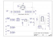
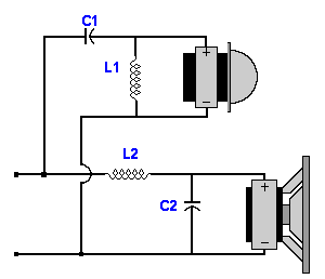
My setup contains the following elements (see photo and schematic):
- DIYinhk USB multichannel XMOS board
- my AK4458 multichannel DAC
- my reclocking board with Crystek CCHD-575 crystal, NB3L553-D buffer and PO74G374A logic gates, supplied from a TPS7A4700 3.3V regulator
The circuit is working good, although it is under testing yet. Before this setup I fed my DAC direct from a MiniDSP USBStreamer, without reclocking the I2S signals. The improvement is obvious: there are more microdetails, finer textures, the instruments are better focused and more separated. Brass instruments and violins are excellent detailed. Overall a more natural presentation, not so fuzzy like a typical "digital" sound.
But! After some experiments I must say that it’s not an easy task to design so a HF circuit correctly. Depending e.g. from the applied bypassing, the sound character changes too! By not adequate setup the higher transients can be
too harsh/grainy and the midrange-bass not so articulated, what I'm actually experiencing with my setup. I’d like to make a little technical “walk around” here, to find and understand the optimal environment for such a circuit.
I’ve found some very helpful literature:
- Application Manual for Power Supply Noise Suppression and Decoupling for Digital ICs
https://www.murata.com/~/media/webrenewal/support/library/catalog/products/emc/emifil/c39e.ashx
- Johnson-Graham: High-speed Digital Design (A Handbook of Black Magic)
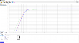
Please find attached an excel-sheet, adapted from this book. I’ve made it for myself, to understand the basics and to have a good starting point. The applied models are relative simple (capacitors modelled only with capacitance and a serial inductance), but I think it doesn’t harm to make a check like this and make some thoughts…
Another try is to collect as good as possible spice models from the manufacturers (Murata, Kemet, Panasonic etc.) and drop them into a simulator (e.g. TINA). Feel free to experiment with that!
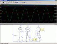
My next step will be to make some jitter measurements with injected noise into the power lines. Will try simply to superpose e.g. 0,1V sinusoidal signal with changing frequency and see what happens on the clock and other outputs… I hope I can determine a reasonable targeted noise floor what a supply line must be achieve to get an appropriate audio playback.
I’ll try to split the psu-lines of the ICs (clock, buffer, gates) and supply them with different voltage regulators. TPS7A4700, LT3042, shunt, LF33CV, etc.
So, I leave rather no questions at the end, because I’ve to experience it myself, but still the message: if you feel to say some advice please make it!
🙂
Thanks for your attention!


