I agree. I redid some of the simulations and gm and mu decrease, but not a lot.@lhquam That 5.1 Vds operating point in your measurement jig is not a good choice if you ask me. It may be fine for some parts, but for others it will be at the edge of the sane operating range. See attached example. I'd go with 3 or 4 Volts, which should be more universally applicable.
Even if the gm and mu values are as in that exhaustive list of measurements, there are ample numbers of LUs with gm over 7S and mu over 4, which results in gm[casc] > 5.1S, which is still good.
Does someone have gm and mu values for the Pass1 SIT? Hello Papa!
https://www.firstwatt.com/pdf/prod_sit1_man.pdf has some curves of the PASS-SIT-1. Depending on where / how I look at them I'd estimate gm = 3 A/V and mu = 15 or so.
I believe Pa did his curves for his specific arrangement for triode operation of Lu, which includes source resistor
The reason I asked about the Pass1 SIT is to see if what parameters the my LU1014D modulated cascode might provide a "pseudo-SIT" with behavior similar to the Pass1.
ask Generg - he's having all files
in fact - memorymemory - Mr. MR is da Man: https://passdiy.tv
edit: that's more like mrmrymrmry

if you can't find LTSpice data for SIT1 there, buzz Mr. MR
in fact - memorymemory - Mr. MR is da Man: https://passdiy.tv
edit: that's more like mrmrymrmry
if you can't find LTSpice data for SIT1 there, buzz Mr. MR
** PASS-SIT-1 ************************************************************
* M. ROTHACHER
*--------------------------------------------------
.SUBCKT PASS1 1 2 3 ; Drain Gate Source
+ PARAMS: MU=19.4880 EX=1.204 KG1=0.7031 KP=81.0 KVB=42.0 VCT=3.616 RGI=1MEG
*--------------------------------------------------
E1 7 0 VALUE={V(1,3)/KP*LN(1+EXP(KP*(1/MU+(VCT+V(2,3))/SQRT(KVB+V(1,3)*V(1,3)))))}
RE1 7 0 1G
G1 1 3 VALUE={(PWR(V(7),EX)+PWRS(V(7),EX))/KG1}
RDS 1 3 1G ; TO AVOID FLOATING NODES
D1 5 2 DX ; FOR GRID CURRENT
R1 5 3 {RGI} ; POSITIVE GRID CURRENT
.MODEL DX D(IS=1N RS=1 CJO=10PF TT=1N)
.ENDS
*--------------------------------------------------

I have a PASS-SIT-1 model that uses my concise model soemwhere around, let me get right back to you.
I have been simulating a single-ended triode circuit similar to the First Watt SIT1 using the LU1014D modulated cascode circuit.
(Note: I have introduced a new parameter A=1/k, which is the Vds expansion factor of the circuit.)
The issue that I am experiencing is the very high voltage gain of the circuit because of μ[casc]=A*μ[J1]. Without global feedback to reduce the gain (and distortion), this makes the distortion much higher that desirable.
In the images below I show two examples:
Image 1: A=9 Ibias=1.5A VdsJ1=4V
Gain=40 (32dB), THD=2.21% OK harmonic spectrum.
Image 2: A=inf Ibias=1.5A VdsJ1=4V Rs=0.2R
Gain=24 (28dB), THD=2.1% Better harmonic spectrum.
The cascode is not modulated => pentode behavior.
Source degeneration used to limit voltage gain to 28dB.
These are not very promising results for a SIT1 type amplifier.
I plan to try a non-feedback source-follower circuits, such as a SIT MUFF or SIT3X.
Attachments


same thing with modern UJN and similar SIC JFets; xconductance is ridiculous, so NFB is a must
well, I'm avoiding degeneration, so that's it
we'll see, when I find time to put pcbs on bench
well, I'm avoiding degeneration, so that's it
we'll see, when I find time to put pcbs on bench
Did you like the math? 😈😈
I'm always in ave how your brain is wired

mine, I'm always thinking in colors
btw. for follower arrangement - difference between modulated and plain cascode will be strictly matter of taste
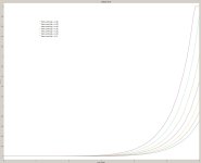
The problem with this plot is that 90% of the information on the plot is not where the device would be used in a linear amplifier.https://www.passdiy.com/gallery/amplifiers/zen-variations-8
"In the case of JFET part LU1014, we note that with a gate voltage of –1 volt, the curve is concave below about 5 amps and 4 volts.
In this range it has that triode character, and this is the area of interest to us here."
.
The attached plot shows ~2A from the top plot to the bottom plot with 60 mV traversed for a gain ~33.
The measurement of the LU1014D gain parameter requires a 4-wire Kelvin measurement. If you rely on the power supply to measure the voltage, you are placing the cabling resistance in the drain and source. This resistance knocks down the gain.
The curve traces look different when disabling remote sense (4-wire Kelvin)
Attachments
That plot was from the LU1014 datasheet, not from Nelson, certainly not from me :
http://www.amplimos.it/images/LU1014D.pdf
Our own-design curve tracer only uses Kelvin measurements for Vgs, Vds and Id.
https://www.diyaudio.com/community/...e-follower-configurations.128571/post-1595846
Post 24~26, for headphone amp use.
Cheers, Patrick
http://www.amplimos.it/images/LU1014D.pdf
Our own-design curve tracer only uses Kelvin measurements for Vgs, Vds and Id.
https://www.diyaudio.com/community/...e-follower-configurations.128571/post-1595846
Post 24~26, for headphone amp use.
Cheers, Patrick
Last edited:
Understood. I was just commenting that the behavior of the device is barely visible in the plot. Most of the plot is wasted space for audio circuit design.
I thoroughly enjoy all of your shared work. Top notch in all regards.
I thoroughly enjoy all of your shared work. Top notch in all regards.
My LU1014D modulated cascode might be fool's gold. More explanation to come....
The much sought-after electronic holy grail.
- Home
- Amplifiers
- Pass Labs
- LU1014D Modulated Cascode