I was just given a number of 100mH/3.5A common mode chokes and am wondering if they can be used like a normal (single inductor) choke to filter AC ripple out of a DC filament supply.
Perhaps one or both of these ways would work following a diode bridge rectifier (attached drawing)?
A. One coil of the choke unconnected, and the other coil in series with the positive rail and bookended with capacitors, like a regular CLC filter. Need to ensure the single winding has enough current capacity.
B. Both coils connected in parallel with respect to each other, and in series with the single positive rail.
What do we think?
Attachments


In CM choke, one winding has DC current in forward direction, and the other (inserted in return line) in the opposite direction. DC magnetization is thus cancelled, so a gapless core can be used, with resulting overall CM inductance greatly increased. Using only one winding or two windings in parallel will cause strong DC magnetization with dramatic drop of inductance.

OK, thank you both. My understanding is that the coils in the CMC are in the same orientation, though. I noted that in euro21's schematic, the phase dots are in are in an opposing orientation (attached closeup). Wouldn't that be a differential mode choke?
Attached also is the datasheet for the product I have, which has the phase dot on the same end of both coils. I can just connect it like euro21, then?
Attached also is the datasheet for the product I have, which has the phase dot on the same end of both coils. I can just connect it like euro21, then?
Attachments

Last edited:
Yes, this connection gives differential mode operation, thus decreasing rectification "noise".
If you reversing one coil, the common mode operation decreasing noises from PT primary->PT secondary.
If you reversing one coil, the common mode operation decreasing noises from PT primary->PT secondary.

Which coil are you using?This is my 801 -filament biased- preamp LT supply.
Yes, try differential mode.OK, so just to be clear, are you suggesting that I wire the choke as in the attached drawing?
I used Bourns CMC (5.6mH or 30mH) in my LT PSU.
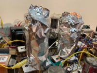
Thanks for the input, euro21. Last night I tried your suggestion of wrapping the 10Ys in foil and connecting them to chassis ground, which didn't change anything. I also went through the entire breadboard to check and tighten every single connection and ensure that the topolgy was correct, and found no problems there. Since failing rectifier tubes can cause 120Hz hum, I replaced the upper rectifier and found no change, then the lower rectifier and found no change. Some other possibilities:
In the present 10Y DC filament supply, I added capacitance to the four 4mH mini chokes, in series, to create a CLCLCLCLC filter. Caps 1, 4, and 5 are 22,000uF, while caps 2 & 3 are 27,000uF. The multiplicative effect of inductors in series should be well enough to filter out AC ripple, I would think. Here is the drawing for both channels.

When the entire amp is running, I now measure 9mV AC on the 10Y filaments, which is down from 43mV before adding more capacitors. The 120Hz hum is audibly a little quieter than before, but still too loud for listening to music. Perhaps it needs yet more filtering, but I wonder if the problem might be from using a single 6.3VAC transformer to power the diode bridges in both channels, as opposed to one transformer per channel.
Next, for increased filtering, I wonder if using common mode chokes, arrayed in series and wired differentially, might be more effective at filtering AC ripple out of the DC filament supply. I've read that CMC chokes are for isolating a circuit from ambient electro-magnetic fields and filtering out high frequency noise. So maybe they won't be effective at removing 120Hz AC ripple. But here's a thought:

Anyway, I'll troubleshoot all the power capacitors tonight, and generally keep hunting that hum.
Attached is also a picture the 10Ys under foil.
- A failed power supply capacitor (will check this tonight)
- Use of a single 6.3VAC transformer to power two diode-bridge DC supplies -- change to one transformer per channel?
- Perhaps amplifier oscillation? It didn't do this with the 26 driving 2A3, but maybe the 10Y is inducing different behavior
- Maybe it simply needs even more DC filament filtering
In the present 10Y DC filament supply, I added capacitance to the four 4mH mini chokes, in series, to create a CLCLCLCLC filter. Caps 1, 4, and 5 are 22,000uF, while caps 2 & 3 are 27,000uF. The multiplicative effect of inductors in series should be well enough to filter out AC ripple, I would think. Here is the drawing for both channels.
When the entire amp is running, I now measure 9mV AC on the 10Y filaments, which is down from 43mV before adding more capacitors. The 120Hz hum is audibly a little quieter than before, but still too loud for listening to music. Perhaps it needs yet more filtering, but I wonder if the problem might be from using a single 6.3VAC transformer to power the diode bridges in both channels, as opposed to one transformer per channel.
Next, for increased filtering, I wonder if using common mode chokes, arrayed in series and wired differentially, might be more effective at filtering AC ripple out of the DC filament supply. I've read that CMC chokes are for isolating a circuit from ambient electro-magnetic fields and filtering out high frequency noise. So maybe they won't be effective at removing 120Hz AC ripple. But here's a thought:
Anyway, I'll troubleshoot all the power capacitors tonight, and generally keep hunting that hum.
Attached is also a picture the 10Ys under foil.
Attachments
I am not convinced that hum primary/single source is 10Y filament.
As you can see this simulation, the 9mV peek 120Hz hum on 10Y filament (using virtual cathode or hum pot) causes only 0.2mV peek disturbance on output.

Try to feed temporarily 10Y filament from guaranteed noise-free power (battery, good laboratory PSU etc.).... and always use for DH tubes virtual cathode or hum pot.
p.s.
Very large first capacitor (after the rectifier) always generate enormous charging pulses, which are stressing the whole PSU (mainly the PT).
For 10Y/801a I use high ripple capacity 4700uF, if the current is higher (PSE 801a or 211), duplicated it.
As you can see this simulation, the 9mV peek 120Hz hum on 10Y filament (using virtual cathode or hum pot) causes only 0.2mV peek disturbance on output.
Try to feed temporarily 10Y filament from guaranteed noise-free power (battery, good laboratory PSU etc.).... and always use for DH tubes virtual cathode or hum pot.
p.s.
Very large first capacitor (after the rectifier) always generate enormous charging pulses, which are stressing the whole PSU (mainly the PT).
For 10Y/801a I use high ripple capacity 4700uF, if the current is higher (PSE 801a or 211), duplicated it.
Last edited:
Test with a battery (+ regulator for the right filament voltage). If you still hear hum, it's not the filament.
Regards, Gerrit
Regards, Gerrit
Thanks for the insight, and for the advice on first caps in power supplies. I think there might be a DC power supply in the equipment that was given to me at the beginning of the week. Will check tonight.
I did put in place a hum pot on the 10Y filaments last week, but it didn't do much except change the tone of the hum.
Last night I measured 19mVAC across the 10Y anode choke (Lundahl LL1668 -- 100H/25mA). Not sure if that's causing the loud hum, but from the node going into the 2A3 grid, it would only be amplified in the output stage by about 4 times at most. Maybe that's enough to cause the hum, and if so, then the lower (10Y) high voltage power supply rail might be the source.
I will try to get some clean DC on those 10Y filaments.
If you are in an experimenting mood, try PFC correction chokes from computer power supplies. Can stand some current and are air-gapped.
Thanks for the suggestion, stevenrotterdam. I will look into PFC chokes.
I am now certain that the noise is coming from the 10Y filament supply. The 2A3 filaments, 10Y filaments, and the two high voltage transformers are all connected to separate power switches. If I run the amp, and then shut it down, it still conducts for a short while as the capacitors slowly lose voltage. I found that when I shut off the power switches in the following sequence --- upper rail high voltage, lower rail high voltage, 2A3 filaments, 10Y filaments -- the 120Hz hum remains, and then disappears instantly once I turn off the 10Y filament.
It turns out I do have two DC bench power supplies that can easily handle the 10Y filaments, so I'll connect them tomorrow after I learn how to use them, and test on something less critical first.
Attachments

Please take care using bench power units for filament supplies.
If the output negative is connected to safety earth (PE), which is often the case, any cathode resistor will be bypassed, if the B+ voltage is also connected to PE
If the output negative is connected to safety earth (PE), which is often the case, any cathode resistor will be bypassed, if the B+ voltage is also connected to PE
Update on the direct-coupled 10Y driving 2A3 SET. It's mostly the circuit from #581, with a stacked power supply, but running 10Y at 280Vak / 15mA (and it has a 1.6K cathode resistor) (see attached image).
The 10Y filaments light up the whole room! I swapped in the DC bench supplies to feed the 10Y heaters. There's no hum, though one of the supplies has a noisy internal fan that runs constantly -- no free lunch! 😆
This finally allowed me to listen to music. It sounds very full-bodied, authoritative, and detailed. Sonically, 10Y is an even better driver of 2A3 than the 26 was, especially with "big" sounding music and complex passages. However, this arrangement was just to get it started and gain a first impression. So I still have to find the best operating point for 10Y and also a sustainable DC filament supply. I'll try AC with a hum pot next, if only for reference, and will then move on to other DC possibilities.
Attachments


Tonight I decided to try AC heating, first by using the transformer center tap to connect to the top of the cathode resistor and bypass cap, and then by using a hum pot with the wiper attached to the same (without the center tap wire). In both cases, 60hz hum was eliminated but the same audible 120Hz hum was still there.
Then I swapped the DC bench supplies back in and it's dead quiet. So, something about the AC filament transformer -- or rather how I'm using it -- is inducing 120Hz hum on the filament, no matter whether it's feeding AC or DC rectification filtering.
I thought maybe I could try passive DC heat with a diode bridge into a series of LC filters with common mode chokes (90mH / 3.5A) wired differentially, or with a full wave diode (not bridge) using the common mode orientation on the outgoing positive from both diodes, and the center tap connected to the negative rail. The negative pin of the filament and the negative ends of the electrolytic caps would all connect to that negative center tap line.
Come to think of it, I wonder if the filtering would be improved if the cathode resistor and cap were connected to the negative of the first cap in the DC filter, so that the negative end of the bridge or the center tap (in the two scenarios) is where the filter is connected to ground, rather than at the filament.
Attachments


Have you tried modeling any of the filament circuits in LT Spice? Can you reproduce the 120Hz you are hearing in yours?
Are you positive that you have everything wired up correctly, all the way back to the transformer secondaries? On a 45 prototyping build setup not unlike yours, I transitioned to chassis and accidentally swapped +/- the phase on one of my filament transformer secondaries. Led to buzz and other problems!
Having a separate transformer for each 10Y would be ideal for grounding and isolation. I've always understood that to be a best practice for DHTs. It's one thing that the dual bench supplies accomplish.
"In both cases, 60hz hum was eliminated but the same audible 120Hz hum was still there."
If you read Anatoly recension See here: it's evident.
Filtered DC filament and output hum:
If you built it correctly, no way that the cause is 10Y filament.
With this brutally filtered raw DC, and use correct virtual cathode (BTW are you have achieved the virtual cathode for all DH tubes?), the output hum (shorted input) below uV region!

Are you measured the filament transformers p-s capacitance?
Are you sure, that the cause isn’t the 100H choke or last CMC in filtering chain (RFI, overloaded PT-choke) ?
Are you measured the -most critical- B+ (415V) from a perspective of hum?
ps.
Instead of suffering to figure out the hum source, I would have preferred to use Rod Coleman regulators with simple filtering. In this case hunting of the hum source limited to wiring and transformers/chokes interactions.
If with the lab LT supply no hum, and PT-rectifier-filtering chain (tested with proper dummy load) gives only mV hum, the cause IMO the transformers interaction (or fatal grounding problem).
If you read Anatoly recension See here: it's evident.
Filtered DC filament and output hum:
If you built it correctly, no way that the cause is 10Y filament.
With this brutally filtered raw DC, and use correct virtual cathode (BTW are you have achieved the virtual cathode for all DH tubes?), the output hum (shorted input) below uV region!
Are you measured the filament transformers p-s capacitance?
Are you sure, that the cause isn’t the 100H choke or last CMC in filtering chain (RFI, overloaded PT-choke) ?
Are you measured the -most critical- B+ (415V) from a perspective of hum?
ps.
Instead of suffering to figure out the hum source, I would have preferred to use Rod Coleman regulators with simple filtering. In this case hunting of the hum source limited to wiring and transformers/chokes interactions.
If with the lab LT supply no hum, and PT-rectifier-filtering chain (tested with proper dummy load) gives only mV hum, the cause IMO the transformers interaction (or fatal grounding problem).
Last edited:
- Home
- Amplifiers
- Tubes / Valves
- Developing a 2A3 SET