Hi all,
Last weekend we did some measurements on a big subwoofer I designed for a friend of mine who will be using it in the LBB Maastricht (The Netherlands), an alternative place for artists, creators and skaters. I am eager to learn what the crowd on this forum has to say about it. The good AND the bad! Maybe we can improve on it with things we hadn't thought of before.
When setting out the design there was a definite constraint: it had to fit in the elevator and fit through most doors. Everything else was no issue. Well, maybe except for price of components of course. Coverage: as deep as reasonably possible without sacrificing too much sensitivity, it is intended for PA use after all.
So... I took the proven 18SW115-4 as a starting point and tried different concepts, mostly FLH and TH. I ended up with a big box that would fit in the elevator and an extender that can be added for extra extension of the usable frequency range, sacrificing a little maximum SPL.
From the looks of it, and from the kind of music that was often going to be played on the system, I suggested to add kickbins to the PA. For that we built the Cubo kick 15, loaded with the 15NLW9300-8.
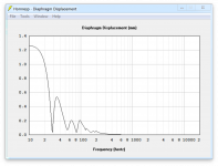
In the attachments I have included the Hornresp simulations of both subwoofer designs, so with and without extender. In the following post I will include the measurements (compared to the Cubo kick for "reference").
Last weekend we did some measurements on a big subwoofer I designed for a friend of mine who will be using it in the LBB Maastricht (The Netherlands), an alternative place for artists, creators and skaters. I am eager to learn what the crowd on this forum has to say about it. The good AND the bad! Maybe we can improve on it with things we hadn't thought of before.
When setting out the design there was a definite constraint: it had to fit in the elevator and fit through most doors. Everything else was no issue. Well, maybe except for price of components of course. Coverage: as deep as reasonably possible without sacrificing too much sensitivity, it is intended for PA use after all.
So... I took the proven 18SW115-4 as a starting point and tried different concepts, mostly FLH and TH. I ended up with a big box that would fit in the elevator and an extender that can be added for extra extension of the usable frequency range, sacrificing a little maximum SPL.
From the looks of it, and from the kind of music that was often going to be played on the system, I suggested to add kickbins to the PA. For that we built the Cubo kick 15, loaded with the 15NLW9300-8.
In the attachments I have included the Hornresp simulations of both subwoofer designs, so with and without extender. In the following post I will include the measurements (compared to the Cubo kick for "reference").
Attachments
-
 Hornresp parameters - no extender.png154 KB · Views: 267
 -
 Hornresp max SPL - with extender.png161.3 KB · Views: 103
 -
 Hornresp displacement - with extender.png135.5 KB · Views: 94
 -
 Hornresp frequency - with extender.png152.7 KB · Views: 113
 -
 Hornresp parameters - with extender.png178.3 KB · Views: 263
 -
 Hornresp max SPL - no extender.png161.7 KB · Views: 279
 -
 Hornresp displacement - no extender.png122.6 KB · Views: 272
 -
 Hornresp frequency - no extender.png139.4 KB · Views: 274
Part 2 - Measurements
We measured outside in hope to eliminate as much room or wall interference as possible. The best space available was directly outside of the building, where we could position the sub on the ground against the wall. This wall extended 20 meters to the left, more than 50 to the right, while going up over 20 meters, albeit with windows in it (of which at least one was cracked at some point 😱). The "view" was towards the river "Maas", which is about 170 meters wide at that point with the first buildings on the other side over 300 meters away.
There was a low concrete ridge on the ground of about 30 cm at 3 meters in front of the subwoofer. Due to my measurement system not being able to measure above 105 dB, I opted to not measure at 1 meter, but at 2 meters, lowering the SPL by 6 dB. The measurement was taken with the mic on the ground. I tried different positions and a bit to my surprise it did matter quite a bit where I put the mic. For example, there were some obvious dips in the frequency response at 4 meters in front of the sub, but I cannot bring myself to believe that that small 30 cm high ridge has anything to do with it... Maybe the windows or the (closed and heavy) wooden door had something to do with it? I don't know.
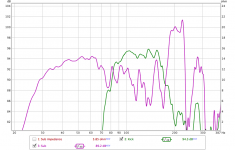
But I managed to get a reasonable measurement with the sub positioned alongside the wall (2nd picture), which is the attached measurement. The extender wasn't finished yet, so I have to go back and do some more measurements and tests when it is (what a burden 😀😉 ). The test signal was 2 Vrms going into a 4 ohm load of the sub, equalling 1 Watt. The same 2 Vrms was used on the Cubo kick 15, which has an 8 ohm speaker, so 0.5 Watts. Taking into account wall loading (+6 dB), distance (-6 dB) and applied power, this should yield a 1 W/m measurement for the sub, while 3 dB should be added to the curve of the Cubo kick 15 to get the 1 W/m equivalent.
But... comparing the measurements with the simulations, I see some discrepancies. The most obvious one being the sensitivity which seems to lack quite a bit. Looking at the impedance curve I don't recognise anything pointing to leaks. The construction was done with 18mm baltic birch and the box is stiffened extensively. The 18SW115 only has 24 hours or so run-in time, so I expect it to change a little over time, but in my experience this does alter the frequency response more than it does sensitivity. Or am I wrong?
Of course we had a little fun and listened to some music as well. I (quickly) dialed in a HP at 20 Hz (48dB) and a LP at 90 Hz (BW24), no EQ on the sub, and a HP at 90 Hz (BW24) with a LP of 200 Hz (BW24) on the cubo kick, also no EQ. So there definitely is room for improvement there. I did some delay adjustments by ear to get as close to the tops as I could.
Apparently we did not only rattle the windows, the people inside said vibrations were felt in the whole concrete building 😀. And also, the next day we got a comment that it sounded pretty awesome... at the houses on the other side of the river 😛
The sound in the videos is from the internal mic of an HTC10. The tops are my "Synergy 2" design discussed here: Synergy horn for 135 dB+.
We measured outside in hope to eliminate as much room or wall interference as possible. The best space available was directly outside of the building, where we could position the sub on the ground against the wall. This wall extended 20 meters to the left, more than 50 to the right, while going up over 20 meters, albeit with windows in it (of which at least one was cracked at some point 😱). The "view" was towards the river "Maas", which is about 170 meters wide at that point with the first buildings on the other side over 300 meters away.
There was a low concrete ridge on the ground of about 30 cm at 3 meters in front of the subwoofer. Due to my measurement system not being able to measure above 105 dB, I opted to not measure at 1 meter, but at 2 meters, lowering the SPL by 6 dB. The measurement was taken with the mic on the ground. I tried different positions and a bit to my surprise it did matter quite a bit where I put the mic. For example, there were some obvious dips in the frequency response at 4 meters in front of the sub, but I cannot bring myself to believe that that small 30 cm high ridge has anything to do with it... Maybe the windows or the (closed and heavy) wooden door had something to do with it? I don't know.
But I managed to get a reasonable measurement with the sub positioned alongside the wall (2nd picture), which is the attached measurement. The extender wasn't finished yet, so I have to go back and do some more measurements and tests when it is (what a burden 😀😉 ). The test signal was 2 Vrms going into a 4 ohm load of the sub, equalling 1 Watt. The same 2 Vrms was used on the Cubo kick 15, which has an 8 ohm speaker, so 0.5 Watts. Taking into account wall loading (+6 dB), distance (-6 dB) and applied power, this should yield a 1 W/m measurement for the sub, while 3 dB should be added to the curve of the Cubo kick 15 to get the 1 W/m equivalent.
But... comparing the measurements with the simulations, I see some discrepancies. The most obvious one being the sensitivity which seems to lack quite a bit. Looking at the impedance curve I don't recognise anything pointing to leaks. The construction was done with 18mm baltic birch and the box is stiffened extensively. The 18SW115 only has 24 hours or so run-in time, so I expect it to change a little over time, but in my experience this does alter the frequency response more than it does sensitivity. Or am I wrong?
Of course we had a little fun and listened to some music as well. I (quickly) dialed in a HP at 20 Hz (48dB) and a LP at 90 Hz (BW24), no EQ on the sub, and a HP at 90 Hz (BW24) with a LP of 200 Hz (BW24) on the cubo kick, also no EQ. So there definitely is room for improvement there. I did some delay adjustments by ear to get as close to the tops as I could.
Apparently we did not only rattle the windows, the people inside said vibrations were felt in the whole concrete building 😀. And also, the next day we got a comment that it sounded pretty awesome... at the houses on the other side of the river 😛
The sound in the videos is from the internal mic of an HTC10. The tops are my "Synergy 2" design discussed here: Synergy horn for 135 dB+.
Attachments
-
 Sub + Cubo Kick 15.png55 KB · Views: 135
 -
 Impedance - no extender.png41.9 KB · Views: 126
 -
 THD.png110.9 KB · Views: 114
 -
 Sub with Stefan.jpeg197 KB · Views: 171
 -
 Sub and Cubo kick 15.jpg614 KB · Views: 174
 -
 Sub test position.jpeg188.8 KB · Views: 152
 -
 Test setup 01.jpg778.5 KB · Views: 146
 -
Vid 01.mp42.6 MB
-
Vid 02.mp43.4 MB
-
Vid 03.mp44.2 MB

Thijs666,Part 2 - Measurements
1)We measured outside in hope to eliminate as much room or wall interference as possible. The best space available was directly outside of the building, where we could position the sub on the ground against the wall.
Due to my measurement system not being able to measure above 105 dB, I opted to not measure at 1 meter, but at 2 meters, lowering the SPL by 6 dB.
2)I tried different positions and a bit to my surprise it did matter quite a bit where I put the mic. For example, there were some obvious dips in the frequency response at 4 meters in front of the sub, but I cannot bring myself to believe that that small 30 cm high ridge has anything to do with it...
3)Maybe the windows or the (closed and heavy) wooden door had something to do with it? I don't know.
4) But I managed to get a reasonable measurement with the sub positioned alongside the wall (2nd picture), which is the attached measurement.
But... comparing the measurements with the simulations, I see some discrepancies. The most obvious one being the sensitivity which seems to lack quite a bit.
5)The 18SW115 only has 24 hours or so run-in time, so I expect it to change a little over time, but in my experience this does alter the frequency response more than it does sensitivity. Or am I wrong?
6)The sound in the videos is from the internal mic of an HTC10.
You have built a real monster sub, construction looks great!
I would not read too much into your frequency response measurement, though seeing the measurements from the other locations would help to ascertain the nature of the discrepancies.
1) At only two meters, the size of the sub and the distance to the wall appear to be a real problem.
2) The small ridge shouldn't be a problem for low frequencies, but the variation of directivity with frequency and resultant variation between in phase and out of phase reflected wall SPL may be.
3) The wall or door would have little effect. If the sub could be placed inside the door the graffitti cat is spray painting, flush with the wall, I suspect the response would be far more similar to the simulation.
4)The "alongside the wall" 200-300 Hz response looks close to the simulation sensitivity.
5) I don't think you are wrong, but a "too stiff" suspension would slightly reduce sensitivity at low frequencies at a one watt drive level, not overall sensitivity.
6) The mic clipping when the camera goes on axis to the sub at close range is an indicator of the amount of upper directivity your big*** sub has even with a 90 Hz BW24 LP.
Given the same outdoor location for measurement, if #3 is not possible, you might try placing the mic at the ground/wall junction rather than out from the wall.
Better yet, lug it down to the river to reduce the influence of the buildings, or short of that, as far from buildings as possible.
Nice work!
Art
Attachments

Great looking sub, there does seem to be a big sensitivity discrepancy, its worth checking your microphone setup has the sensitivity you expect, perhaps you could use a tweeter mounted to a flat baffle with a known response to check this. Also although harder simplifying the acoustic environment to a ground plane (car park for example) would be easier to deal with. Another technique is to measure the internal SPL of the box to get the response:
Internal microphone to determine maximum SPL - Bass Gear - Data-Bass Forums
(although this doesn't solve your sensitivity issue)*
*not sure how this would work for a TH
Internal microphone to determine maximum SPL - Bass Gear - Data-Bass Forums
(although this doesn't solve your sensitivity issue)*
*not sure how this would work for a TH
Dang, that looks fun!! its a familiar sim layout(similar). We probably agree its very aggressive and punch in the face bass. exciting
Thanks Art for your elaborate reply and thanks also Kipman.
When the extender is ready we'll do some more measurements. If possible we'll try your suggestion to position it in the door opening to see if that changes things. And we'll also try with the mic positioned at the wall/ground junction. I hadn't thought of doing that.
I did think about lugging it as far away from the building as possible, but that would be "only" about a meter of 15 (45 feet) away. Any further and it would be a "submarine" (pun intended🙂). I didn't do the math, but I think this would still interfere a lot with the measrument. My hope is to find a field with no buildings at all where we can measure...
I'll check my measurement setup for calibration. I had hoped the inclusion of the measurement of the Cubo Kick 15 would help me validate the results.
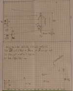
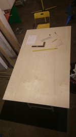
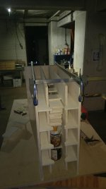
The layout of the horn is symmetrical, by the way, so the load on the membrane is as even as possible. It starts with one single horn section which gets split up at the end, as can be seen in the layout plan and construction photos (baffle plate is been glued on in the first one).
When the extender is ready we'll do some more measurements. If possible we'll try your suggestion to position it in the door opening to see if that changes things. And we'll also try with the mic positioned at the wall/ground junction. I hadn't thought of doing that.
I did think about lugging it as far away from the building as possible, but that would be "only" about a meter of 15 (45 feet) away. Any further and it would be a "submarine" (pun intended🙂). I didn't do the math, but I think this would still interfere a lot with the measrument. My hope is to find a field with no buildings at all where we can measure...
I'll check my measurement setup for calibration. I had hoped the inclusion of the measurement of the Cubo Kick 15 would help me validate the results.
The layout of the horn is symmetrical, by the way, so the load on the membrane is as even as possible. It starts with one single horn section which gets split up at the end, as can be seen in the layout plan and construction photos (baffle plate is been glued on in the first one).
Attachments

- Home
- Loudspeakers
- Subwoofers
- Big *** subwoofer - measurements -> opinions?