About atenuation resistor in the high pass cut-off of midrange and tweeter for the caps and coils values calculation ?
I have a doubt, and need confirmation, please.
About passive filters please,
when choosing a cut off frequency, we need the impedance of the driver at this frequency to find for instance the value of the caps for the high pass.
1) If one is needing some attenuation by a resistor before the high pass, should he add the Z value of this resistor to the driver impedance at the cut-off frequency to calcul the caps value an coil one (if going second order or more) ?
2) What about the low pass of a mid as well when there is a serie attenuation resistor in the filter (or L-pad), please ? Should one add the attenuation resistor Z value to the DCR of the coil to have an idea of the magnitude behavior of the midrange driver in all its pass band (so from the high pass to the low pass in the order the AC signal sees it from the amp ? Rephrased differently : if the coil DCR is changing in the pass band used between the low end of the mid frequency (high pass of the cap) and the high end (low pass of the coil) of the midrange, does the total spl attenuation is varying according the frequency ( because of the non linearity in impedance of the coil) ?
I am also asking because sometimes we need to work with two drivers that have an important impedance gap where they met (cut-off frequency).
I do not know if the question makes sense but thanks for your answers.
To make the x-over happen at frequency and steepness you want it to have, the XO better see a flatfish impedance - but you know this. Use conjugate/zobel...? I don't see why the impedance need to be the same at XO if you use a low output impedance amp... if not , well...
//
//
, TNT, I am not asking about driving the load but which impedance I should use to the crossover frequency calculation of a medium or tweeter high pass.
I was simply thinking when you had for instance the low end of the midrange at 4 ohms where you need to cut off and you need to atenuate the spl by a serie resistor, for instance 4 ohms resistor (that moves up your final impedance to 8 ohms), the impedance number to take was the new one, i.e. : 8 ohm and not 4 ohms.
MvdG answered, is it is the initial impedance of the driver alone that should be taken if the resistor is before the capacitors high pass.
Thanks.
Unfortunately, that's not quite what I meant.
When the resistor is straight in series with the driver, you can just add its resistance to the driver impedance. So far so good.
When the resistor is on the other side of the filter, it turns into a doubly terminated filter, probably unequally terminated. You can then try to look up the correct component values for unequally doubly terminated filters in old filter handbooks such as Zverev's famous book from the 1960's (which covers a lot, but no Linkwitz-Riley filters), or write out the network equations and try to equate the coefficients to the desired values, or iterate with a simulator (which can be partly automated if it has an optimizer) or iterate with an experimental set-up until you get what you want. In any case, it is not just a matter of adding the resistance of the resistor to the driver impedance anymore.
thanks for tht precision. Speaking of the resistor before the filter, so attenuation without the L-pad, in the simple purpose of spl attenuation before the high pass of the said driver:
Do you talk still about the upper driver in the filter interaction or at least as the resistor is before the upper driver then that resistor will be somewhere in serie also with the low pass coil of the lower bass driver... and just changes the game for the bass driver only?
So in the low pass area of the cut-off: the low pass impedance there is the sum of the coil DCR at that cut-off low pass frequency added to the high pass atenuation resistor of the midrange driver.... that sum value moving in all the low pass band cause the DCR of the coils change when the frequency is moving ?
So you are meaning the resistor in itself is seing at one of its termination the impedance side of the low pass and at the other side termination, the impedance of the driver ?
I have not the mathematical knowledge to talk and understand the subject, my purpose is indeed to enter the rigth numbers - impedance and frequency cut-off in a crossover simulator, to make acurate sims enough after the acquisition of the impedance driver is made. Of course about the magnitude purpose and phase in the crossover area but also to avoid big issues as a too lowish impedance (though ampere and watts are cheap today) or phase too tigth knees.
I answered only your question 1) because I didn't fully understand question 2). I don't understand post #8 either. The way I interpreted it, question 1) just related to a high pass filter with a tweeter and a resistor.
Could you draw a schematic of the configuration you have in mind? Hopefully that will help me to understand you better.
Could you draw a schematic of the configuration you have in mind? Hopefully that will help me to understand you better.
As an ancient IT, I like to wear analogic watches... that's life !Time to go DSP ;-)
//
I think I am more the one that haven't understood you when you talked of the two side of that attenuation resistor in the filter behavior after the #5 answer.
So the resistor doesn't change the high pass cut-off calculation cause its impedance doesn't change the impedance of the driver seen from the caps in between. That is the ok and simple answer I was looking for.
Indeed when I sim, the impedance is climbing more after the cut-off frequency with the resistor than without. but the impedance at the cut off exactly is staying the one of the measured raw driver.
The second part of my post and that has no interest for me, is comming from the fact you said a resistor after a filter is enterring this time into the calculation.
And seen from an amp, the midrange spl attenuation resistor is just after the low pass filter (coil) of the bass driver. So I wondered also how it could affect the low pass filter for the bass driver as well. Clearer ?
Last edited:
Do all simulators take that effect into account?
I suppose the aspect of "lumping" come into play... i.e. things dont always work like different entities but rather as a bunch... e.g. if you solder a resistor to the plus pole or the minus pole on a driver don't matter if you look at that group as a 2-pole circuit....
xsim ?
//
I suppose the aspect of "lumping" come into play... i.e. things dont always work like different entities but rather as a bunch... e.g. if you solder a resistor to the plus pole or the minus pole on a driver don't matter if you look at that group as a 2-pole circuit....
xsim ?
//
Last edited:
With the risk of missing the train... 🙂 (pun intended!)
//
The DSP active filter I want would cost too much... I fear the cheap I/V filter of Mini DSP and like low cost DSP.
A passive filter is like an old car or an analogue watch : working all the time, but if you are in the train (pun intented too : Einstein relativity illustration)
Last edited:
Yes, for simple works before Vituixcad I use mh-audio on line filter calculation plus X-sim, after having took the impedances of the raw drivers plus the drivers with the filters when it is studying existing loudspeakers (refurbishing or retro engeenering for learning pleasure)
Last edited:
What I meant is simply this. If I calculated it correctly, these are two second-order Linkwitz-Riley high-pass filters with 3 kHz cut-off frequency (-6.02059... dB).

The one with the 2.2 ohm resistor directly in series with the 6 ohm load can just be calculated by filling in 8.2 ohm in the equations for an ordinary voltage-driven Linkwitz-Riley filter. The other can't, and all its component values are different from the other filter, although the capacitance is pretty close.
The one with the 2.2 ohm resistor directly in series with the 6 ohm load can just be calculated by filling in 8.2 ohm in the equations for an ordinary voltage-driven Linkwitz-Riley filter. The other can't, and all its component values are different from the other filter, although the capacitance is pretty close.
This is very interesting and just what I've been asking here...
https://www.diyaudio.com/community/threads/3-way-sealed-bass-ob-dipole-mid-hi.398072/post-7322278
I realised the L Pads on 2 drivers in a 3way was making the overall system impedance way too low so have switched to just a series resistor. Now need to reconsider the filter values and maybe look at zobels.
Just in case it is of use to anyone, this is what I calculated for a second-order LC high-pass with termination on both sides.


Getting back to your original question (kind of), R1 and C can be swapped (post # 18) and you will get the same results.
Hi diyiggy,
few observations quickly playing around with VituixCAD and the Kontiainen demo project data shipped with it. I'm not sure if these answer to your particular questions, but might be helpful so here goes 🙂
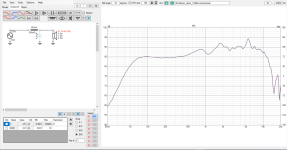
- Calculating crossover components by hand would be quite hard, as one really needs the acoustic slopes in the end. Example: here is a woofer naked and then second order electrical Bessel low pass filter at 2khz, but the acoustic low pass is more like 4th order LR slope somewhere around 6kHz due to natural response of the driver. Also woofers impedance would affect so you'd really need the measured impedance for crossover calculation for accurate results.
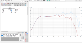
- for midrange driver, you can pad it down a bit using thin wire inductor with high resistance to it. Increased series impedance works as pad reducing current through the driver, but it also reduces electrical damping and the bass response peaks some. While this might be good thing in some cases it could be bad thing on some other, something to check out nevertheless. This would happen with a resistor as well so it would be best to use a woofer that needs no attenuation, or as little as possible.
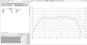
- pad before or after a filter? If its before, full bandwidth sound passes through, so extra heat, extra juice from amp. For this reason, I think, tweeter pad is usually after the high pass filter, capacitor in front prevents low frequency power heating the pad.
Here is heat dissipation on the low pass filter coil in above coil pad example.
50W amplifier power with music content, not too bad. If it was full blown sine / squarewave instead, much more heat in this example.
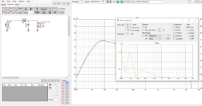
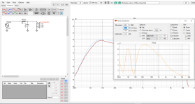
- here is tweeter high pass. Seems to work nicely with calculated text book filters as impedance is not funky and no breakup messing it all up. Acoustic slope is not that far off as with the woofer above. 2nd order electrical LR filter makes roughly 1.5kHz 4th order LR acoustic slope.
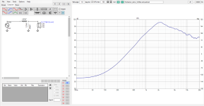
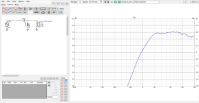
Here is few db L-pad before and after, not too big difference in resulting response. The overlay trace is the filter without pad.
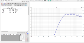
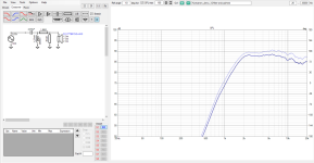
Difference is mostly how power is dissipated, much less amplifier power is wasted when the pad is between the filter and tweeter, capacitor blocks all the lows. While pad before filter wastes several Watts on low frequencies, for nothing, there is only few milli Watts wasted and required from the amplifier, if pad is after the filter.
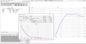
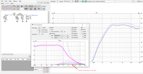
If anything, for best results the modern simulators seem very valuable, all data visible and tunable in real time, less trial and error and perhaps faster end results. Although, doing it by hand for the fun and experience why not 🙂 Also toying around in the simulator is golden, gives insight to anticipate some of the things one would encounter in the wild sooner or later.
few observations quickly playing around with VituixCAD and the Kontiainen demo project data shipped with it. I'm not sure if these answer to your particular questions, but might be helpful so here goes 🙂
- Calculating crossover components by hand would be quite hard, as one really needs the acoustic slopes in the end. Example: here is a woofer naked and then second order electrical Bessel low pass filter at 2khz, but the acoustic low pass is more like 4th order LR slope somewhere around 6kHz due to natural response of the driver. Also woofers impedance would affect so you'd really need the measured impedance for crossover calculation for accurate results.


- for midrange driver, you can pad it down a bit using thin wire inductor with high resistance to it. Increased series impedance works as pad reducing current through the driver, but it also reduces electrical damping and the bass response peaks some. While this might be good thing in some cases it could be bad thing on some other, something to check out nevertheless. This would happen with a resistor as well so it would be best to use a woofer that needs no attenuation, or as little as possible.

- pad before or after a filter? If its before, full bandwidth sound passes through, so extra heat, extra juice from amp. For this reason, I think, tweeter pad is usually after the high pass filter, capacitor in front prevents low frequency power heating the pad.
Here is heat dissipation on the low pass filter coil in above coil pad example.
50W amplifier power with music content, not too bad. If it was full blown sine / squarewave instead, much more heat in this example.


- here is tweeter high pass. Seems to work nicely with calculated text book filters as impedance is not funky and no breakup messing it all up. Acoustic slope is not that far off as with the woofer above. 2nd order electrical LR filter makes roughly 1.5kHz 4th order LR acoustic slope.


Here is few db L-pad before and after, not too big difference in resulting response. The overlay trace is the filter without pad.


Difference is mostly how power is dissipated, much less amplifier power is wasted when the pad is between the filter and tweeter, capacitor blocks all the lows. While pad before filter wastes several Watts on low frequencies, for nothing, there is only few milli Watts wasted and required from the amplifier, if pad is after the filter.


If anything, for best results the modern simulators seem very valuable, all data visible and tunable in real time, less trial and error and perhaps faster end results. Although, doing it by hand for the fun and experience why not 🙂 Also toying around in the simulator is golden, gives insight to anticipate some of the things one would encounter in the wild sooner or later.
Last edited:
- Home
- Loudspeakers
- Multi-Way
- About atenuation resistor in the high pass cut-off of midrange and tweeter for the caps and coils values calculation ?