Hello,
I’ve recently bought a not working NAD 216THX for $110 the seller stated only relay not working needs replacement, I bought the amp knowing it’s not only the relay so not a disappointment, I did replace the relay with the exact same model not newer not older, and still nothing. All the caps seem visually fine so I’ve taken some voltage readings on some jumpers that make logical sense to me as I don’t know where to get started. Just some background I’ve never worked on amps or any kind of other electronics other than making some crossovers. Here are the readings I got (this is with black probe on chassis and red probe probing and AMP powered on)
Left Ch.
J303 -19.3V
J305 -61.9V
J307 0V (makes sense it’s GND)
J309 62V
Right Ch.
J304 -21.5V
J306 -61.7V
J308 0V (makes sense it’s GND)
J310 61.8V
+Vl 61.8V
+Vr 61.8V
-Vl -61.8V
-Vr -61.8V
I’ve also included some pictures of the AMP and I found the service manual but once again, don’t know where to start.
Attachments
I would first check for DC voltage on the speaker outputs. You might be able to "see" it right when the amps turns on, depends how quickly the relay reacts (black probe on black speaker output, red on red speaker output).
If you can't see the voltage there, you will need to go before the relay and carefully probe IC201 on PIN 3 for right channel and PIN 6 for left channel. anything <1Vdc should be fine.
The relays are none to go bad, however yours looks to have been replaced, although I'm not sure you can still get those DEC relays - I had to use an Omron. If there's no DC on the output, then lightly tap on the relay with the plastic (blunt) handle of a screwdriver, that will un-stick the contacts and if it "clicks in" then it is likely the relay is most of the problem.
Checks those and report back and we can go from there.
Good luck - these are great amps IMO - hope you get it back up and running.
Thanks for the reply, I'm writing this as I go through testing it:
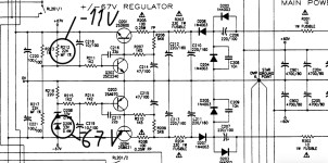
Tried to probe the speaker outputs, when turned on idles at 0.2V when just turned on jumps to 0.25V then goes back down to 0.2V
-6.03V on blue circle
0V on red circle
(picture included)
tapped relay lightly, no click, tapped relay hard, no click
Tried to probe the speaker outputs, when turned on idles at 0.2V when just turned on jumps to 0.25V then goes back down to 0.2V
-6.03V on blue circle
0V on red circle
(picture included)
tapped relay lightly, no click, tapped relay hard, no click
Attachments
I think I misread the schematic the IC PIN 2 is for the Right Channel. You can also measure PIN 8 and 4 for +/-15V to make sure the IC is working.
Beside that - your previous measurement appears to indicate your left channel has DC and causing the protection relay to stay in "mute" mode, not "click in" and allow signal to pass through to the speakers. This would indicate you may have a problem with the outputs (the big transistors on the large heatsink) - my amp had 2 pair that were blown, others tested fine, but I replaced all of them just to be sure.
First job - find what causing the -6Vdc on the outputs - repair and test the amp to make sure it works correctly. Then decide if replacement/reconditioning is worth the expense to you.
Replacement/Reconditioning - might be good to replace are the capacitors on the amplifier and supply board. Not sure you have to do the big supply caps (those will be ~$4-5 each), but to re-cap the whole amp is ~$30-40 for high quality caps - you could also go lower quality and save $10, up to you it's DIY.
I also replaced 3-4 resistors on the power supply board that were out of spec. NAD has a habit of running caps and resistors right at there maximum suggested rating, so they tend to fail right at that 15-20 year mark. Looks like yours is original, so you might have a few more years before that's necessary, but inexpensive insurance IMO.
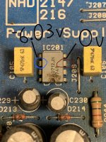
IC201: Used the graph below to locate pins, black probe on ground red probing
Pin 1: -0.47V
Pin 2: -6.61V
Pin 3: -15.37V
Pin 4: -15.75V
Pin 5: 0V
Pin 6: -6V
Pin 7:-0.47V
Pin 8: -0.75V
If i understand this correctly the Outputs are fine no?
Pin 1: -0.47V
Pin 2: -6.61V
Pin 3: -15.37V
Pin 4: -15.75V
Pin 5: 0V
Pin 6: -6V
Pin 7:-0.47V
Pin 8: -0.75V
If i understand this correctly the Outputs are fine no?
Attachments

I did IC202 maybe it will tell something, this is with amp plugged in and turned on, black probe on ground.
Pin 1 = -7.75V
Pin 2 = 0V
Pin 3 = 0V
Pin 4 = 0V
Pin 5 = 0V
Pin 6 = 58V
Pin 7 = 0V
Pin 8 = 0V
Pin 9 = 0.02V
Pin 1 = -7.75V
Pin 2 = 0V
Pin 3 = 0V
Pin 4 = 0V
Pin 5 = 0V
Pin 6 = 58V
Pin 7 = 0V
Pin 8 = 0V
Pin 9 = 0.02V
I think something went wrong along the way of testing because first time i probed IC202 it gave me more values than 0V and when i did my 2nd round of probing to get more accurate results I got 0 on the pins stated above, is it possible i shorted something along the way ? I have double checked that black is on ground and that my multimeter is doing what it needs to and it's all fine.
According to IC202 datasheet (TA7217P) - IC201 PINs 2 & 3 feed the DC protection trigger on IC202, next step I would try to narrow this down is take voltage from IC202 all 9 pins (but at least pins 1,2,3 and 6)
Looking at your measurements on PIN 2 & 3 on IC201 - it appears the amp is either in Mute or Protection mode (-6Vdc on both pins - need to be at 0Vdc). I would also try and measure for DC right after the amplifier - this would confirm the DC on the output. I included a few places you can take this measurement (Right Channel board),. BE VERY CAREFUL - a slip of the probe will most certainly damage the amplifier board. Hoping one of these points is easy to access or you can use meter clip leads.
It is a little strange that both amp channels would be bad - this is making me think it is power supply or something else common to both channels. Also why I went to the Relay as my first thought.
didn't see your earlier post - something is going on with IC202 - you should at least have -52 to -56 on PIN 5, opposite polarity as PIN 6. You should also see voltages on PINs 2 and 3 (-6.6 and -6.0 from IC201 PINS 2 and 6).
I would try again, and before anything make sure you probe the +VL, -VL and O/P points on the edge of the amplifier board - this will tell us if the amps are getting power (+/-56Vdc) and if you have Output (want it to have close to 0 Vdc).
I would try again, and before anything make sure you probe the +VL, -VL and O/P points on the edge of the amplifier board - this will tell us if the amps are getting power (+/-56Vdc) and if you have Output (want it to have close to 0 Vdc).
R376 = -21.2
Right Channel
+VR = 61.5V
-VR =-61.5V
O/P = -21.5V
Left Channel
+VL =61.5V
-VL = -61.2V
O/P = -19.3V
Double checked, triple checked these are the read-outs.
By the way just wanted to thank you for guiding me through this thus far.
Right Channel
+VR = 61.5V
-VR =-61.5V
O/P = -21.5V
Left Channel
+VL =61.5V
-VL = -61.2V
O/P = -19.3V
Double checked, triple checked these are the read-outs.
By the way just wanted to thank you for guiding me through this thus far.
Well - this tells us you have a very similar problem on both channels and that you have DC on the output so the amp is in protection. I may have also reached the limit of my knowledge of reading the schematic to know why.
I can tell you, my next step would be to test the output transistors (and work backwards from there to the drivers, pre-drivers, etc.) and without any power to the amplifier - using the diode test function, look for shorts between Base, Collector and Emitter (BCE) of those transistors. The outputs will be BCE if you are looking at the front of the transistor, you will need to pull up the datasheet for the drivers to confirm the BCE orientation, but first check for any shorts between any combination of those pins (ie BC, BE, CE). Notate which transistors are showing shorts and then we can try to make an educated guess on what to start removing and doing final testing on out of circuit.
I can tell you, my next step would be to test the output transistors (and work backwards from there to the drivers, pre-drivers, etc.) and without any power to the amplifier - using the diode test function, look for shorts between Base, Collector and Emitter (BCE) of those transistors. The outputs will be BCE if you are looking at the front of the transistor, you will need to pull up the datasheet for the drivers to confirm the BCE orientation, but first check for any shorts between any combination of those pins (ie BC, BE, CE). Notate which transistors are showing shorts and then we can try to make an educated guess on what to start removing and doing final testing on out of circuit.
So I've watched like 3 videos on testing transistors for shorts and still don't understand it however, I think the readings I have mean they aren't shorted, my multimeter also acts differently than how other's work. My multimeter in diode mode shows a 1 then changes to a number no beep or similar. All of the measurement below were constant numbers, not changing. I can see if i sometimes touch the other leg of a transistor that the number pops up for a second like when someone with a different multimeter how it beeps for a split second so that might be useful to know for future testing. These are all of the big transistors mounted to the side heat sinks. From the measurements I've got here something is telling me I didn't test them correctly for short. I've attached some photos of how I did it so please correct if I did something wrong, unless somehow none of them are shorted.
The numbering goes like this C for Collector E for Emitter-NPN or PNP being the transistor type-Transistor on circuit.
Black on Collector red on Emitter
CE-NPN-Q905: 575
CE-NPN-Q901: 575
CE-NPN-Q333: 577
CE-NPN-Q329: 577
Black on Emitter Red on Collector
CE-PNP-Q331:585
CE-PNP-Q335:585
CE-PNP-Q903:585
CE-PNP-Q907:585
Black on Collector red on Emitter
CE-NPN-Q905: 575
CE-NPN-Q906:537
CE-NPN-Q902:537
CE-NPN-Q334:537
CE-NPN=Q330538
Black on Emitter Red on Collector
CE-PNP-Q332:548
CE-PNP-Q336:548
CE-PNP-Q904:545
CE-PNP-Q908:545
Attachments


you are close - do the same measurements but - on the NPN, you will have Red on Base (left most pin) and then touch black to Collector (middle pin) and then Emitter (right pin) - the two measurements will show the diode drop of 0.500 - 0.600 mV and prove none are shorted. Switch leads around for a PNP transistor (Black on Base pin) and take same measurements as above but using the red probe. If you get a "0" or "OL" on your meter, trying switching the leads, so if you have Black on Base and red on C-E, trying the other way around, Black on Base and Red on C-E.
Collector-emitter is not as definitive as the measurements I'm having you do above. We might be looking at a single bad junction, B-C or B-E on one of there transistors. Give it a try on one channel to start and post results, then we can go from there.
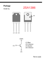
EDIT: PNP is the 2SA1386, NPN is the 2SC3519.
Collector-emitter is not as definitive as the measurements I'm having you do above. We might be looking at a single bad junction, B-C or B-E on one of there transistors. Give it a try on one channel to start and post results, then we can go from there.
EDIT: PNP is the 2SA1386, NPN is the 2SC3519.
I had a Nad amp that went bad.I found one of the high wattage resistor solder joints had let go.maybe try tugging on all their leads.Its worth a try and only takes a few minutes.
@bullittstang Thanks, I will do this tomorrow and give an update.
@oreo382 Will give this a try too thanks.
@oreo382 Will give this a try too thanks.

Just a quick update, I've bought a new multimeter which should be coming on Wednesday so I'll be able to provide better readings since it was very difficult getting the probes where I need them with this cheap multimeter. So until I get it I won't do anything.
good idea - not worse than chasing you tail, because of an invalid measurement. A good DMM is always money well spent!
New multimeter arrived and tested all transistors attached to big heat sink including Q317+Q318 if you don't want to read the wall of text below nothing is shorted as far as i understand
Red on left most pin (base according to @bullittstang) then collector (middle) then emitter (right most)
Q905:NOT SHORTED
BC=520
BE=527
Q901:NOT SHORTED
BC=520
BE=526
Q333:NOT SHORTED
BC=521
BE=527
Q329:NOT SHORTED
BC=519
BE=526
Black on base (left most pin) then collector (middle) then emitter (right most)
Q331:NOT SHORTED
BC=509
BE=516
Q395:NOT SHORTED
BC=511
BE=516
Q903:NOT SHORTED
BC=510
BE=517
Q907:NOT SHORTED
BC=509
BE=516
Red on left most pin (base according to @bullittstang) then collector (middle) then emitter (right most)
Q906:NOT SHORTED
BC=521
BE=526
Q902:NOT SHORTED
BC=520
BE=526
Q334:NOT SHORTED
BC=520
BE=526
Q330:NOT SHORTED
BC=520
BE=526
Black on base (left most pin) then collector (middle) then emitter (right most)
Q332:NOT SHORTED
BC=530
BE=532
Q336:NOT SHORTED
BC=530
BE=532
Q904:NOT SHORTED
BC=527
BE=531
Q908:NOT SHORTED
BC=527
BE=530
Red on right most pin (base) (2SC3423)
Q318+Q317=NOT SHORTED
Red on left most pin (base according to @bullittstang) then collector (middle) then emitter (right most)
Q905:NOT SHORTED
BC=520
BE=527
Q901:NOT SHORTED
BC=520
BE=526
Q333:NOT SHORTED
BC=521
BE=527
Q329:NOT SHORTED
BC=519
BE=526
Black on base (left most pin) then collector (middle) then emitter (right most)
Q331:NOT SHORTED
BC=509
BE=516
Q395:NOT SHORTED
BC=511
BE=516
Q903:NOT SHORTED
BC=510
BE=517
Q907:NOT SHORTED
BC=509
BE=516
Red on left most pin (base according to @bullittstang) then collector (middle) then emitter (right most)
Q906:NOT SHORTED
BC=521
BE=526
Q902:NOT SHORTED
BC=520
BE=526
Q334:NOT SHORTED
BC=520
BE=526
Q330:NOT SHORTED
BC=520
BE=526
Black on base (left most pin) then collector (middle) then emitter (right most)
Q332:NOT SHORTED
BC=530
BE=532
Q336:NOT SHORTED
BC=530
BE=532
Q904:NOT SHORTED
BC=527
BE=531
Q908:NOT SHORTED
BC=527
BE=530
Red on right most pin (base) (2SC3423)
Q318+Q317=NOT SHORTED
Attachments

Since these outputs look okay - Use a good magnifying glass to go over the power supply - looking for any brown spots on resistors or the board and using your meter to check resistor values and match to the schematic. Also check all the diodes (black probe on black line on diode, red probe on other diode lead - you should get 0.5 to 0.7 mV) Seems likely something on the power supply might be the issue and pushing the board into mute/protection state. My board had two bad resistors, a large 2-3w resistor that had un-soldered itself from the heat and a bad capacitor and without proper +/-15V the relay wasn't engaging on start-up. Maybe it will be as easy as that - NAD is known for running Caps and Resistors at the edge of safety, due to heat generated nearby.
I assume you took the amp channel out of the chassis to get these measurements? If not, that would be my next step and do this same process for each transistor working back from the outputs.
Left Channel testing process: Outputs (checked), Q326/Q328, Q322/Q324, Q318 (checked), Q320, Q314/Q316 and see if any of those give a "odd" value (see your previous measurements for what is normal (0.5 to 0.6 mV as each junction) Then if you still can't find an issue check the inputs Q302/Q304, Q306/Q308 and Q310/Q312. You can start at either side totally up to you, but trying to help you narrow it down to a single or a few transistors because in the end you will need to remove them, check them out of circuit to confirm there is a problem and then replace (either with one you pulled out (if okay) or a new transistor).
- Home
- Amplifiers
- Class D
- NAD 216 not coming out of protection mode