My KT150 PP project showed a lot of distortion yesterday. I discovered today that 2 cathode resistors (2.2 Ohm each) had gone south. One measured 33 Ohm, another 160 Ohm.
In the cathode lead I have a string of 3 resistors: 2.2 Ohm, 2.2 Ohm and 1 Ohm, 5.4 Ohm in total. With an automated bias module the cathode voltage is compared with a voltage reference. This works fine and I had set the cathode current to 90 mA.
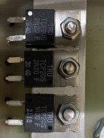
Of course I ordered new resistors today (TO-220 again, now 50 Watt max.). I know the cooling is not exceptional, but with 2.2 Ohm and 90 mA (0.01782 Watt)?
I just cannot understand what may have caused damage to these resistors.
Regards, Gerrit
In the cathode lead I have a string of 3 resistors: 2.2 Ohm, 2.2 Ohm and 1 Ohm, 5.4 Ohm in total. With an automated bias module the cathode voltage is compared with a voltage reference. This works fine and I had set the cathode current to 90 mA.
Of course I ordered new resistors today (TO-220 again, now 50 Watt max.). I know the cooling is not exceptional, but with 2.2 Ohm and 90 mA (0.01782 Watt)?
I just cannot understand what may have caused damage to these resistors.
Regards, Gerrit
Attachments
KT150 with adjustable fixed bias, set to 90mA, Correct?
1. The maximum DC return resistance for g1 that is using fixed bias is 51k Ohms.
Are you using more than 51k?
Thermal Run-Away?
2. Is the screen dissipating more than 9 Watts?
Perhaps the screen overheated and "fell" onto g1, until power was removed (like an open cathode sense resistor series string).
3. For any more guesses, it is suggested that you post a complete and accurate schematic.
$0.03
(adjusted for inflation).

Bias for G1 is below 51K and taken care of by the bias automation module. This module adjusts the G1 voltage by changing the cathode resistors. Regulation is perfect and both tubes allways draw exactly the same current (Class A only). 90 mA is the cathode current, so plate + screen. During this “situation” the tube was used in Ultra Linear mode.
G2 should allways be below 9 Watt (and with a temporary new cathode resistor it is indeed). I will definitely keep monitoring this, as I have seen the screen glowing slightly orange a few times during some testing. When I saw this I switched the circuit off immediately.
I cannot present a diagram now, this is something for the comin winter period.
The film resistors were purchased from a well known distributor (Conrad). I purchased new Vishay’s now.
Regards, Gerrit
Woah that is bizarre. Those things should be able to take amps without trouble. I'm leaning towards Euro21; dodgy supplier. Unless your heater supply somehow shorted to them?
Hi Merlin,
The defective resistors are from “TRU COMPONENTS” and sold by Conrad as their “home” brand. They are supposed to eat 35 Watts when properly cooled.
I hope the Vishay’s (max. 50 Watt) are better…
I’m sure nothing happened to the heater supply (6.3VDC made from 6.3VAC with a low drop regulator).
Regards, Gerrit
gerrittube,
You said:
"I have seen the screen glowing slightly orange a few times during some testing".
OUCH!
I hate when that happens.
Typically, in Ultra Linear Mode, the quiescent screen voltage is slightly higher than the quiescent plate voltage, because . . .
The Whole primary DCR "sees" the plate current.
The B+ to Ultra Linear tap's lower DCR "sees" the Sum of the quiescent screen current Plus the quiescent plate current.
Class A operation:
During push pull operation, each plate current varies from 2 x the quiescent plate current [or more], to a very low plate current (almost all the way to cutoff).
The quiescent plate plus screen current may be 90mA, and the Average plate plus screen current may be about 90mA;
But the peak current of each tube during its part of the signal cycle, is far in excess of 90mA (it has to absorb the 180mA of the fully-on tube as it operates in Class A.
If either tube ever goes into cutoff, the circuit is Class AB.
If that happens, the peak current of the other tube will go to at least 180 mA.
Last edited:
Some extra clarifications:
For UL I have a 1K power resistor, to prevent the screen voltage to become higher than the plate voltage. So this should be safe. I do suspect one tube is not 100% any more. I do have new tubes in stock for later use, when this built is finished.
My power supply is 600 VDC (MOSFET regulated within 1% between zero and full load).
I’m puzzled about you remarks regarding the class A operation. When monitoring the plate current with a DMM or analog meter it never gets any higher than 90 mA per tube, so that’s 180 mA per channel. This current is as stable as a rock, both driven and silent.
Regards, Gerrit
Class A operation of the push tube, of the pull tube [and for single ended tubes too]:
When measuring the voltage across a cathode current sense resistor . . .
A DMM that is set to measure DC Volts, has a built-in Integrator (either a capacitor, or a microprocessor integrator program).
Therefore, it will read 90ma, even though the instantaneous current goes from a few mA to 180mA during the signal positive and negative peaks.
Measuring Instantaneous current in a cathode sense resistor, is a Perfect Function of an oscilloscope and scope probe.
Take a look and see what the range of current is.
In Ultra Linear, the maximum specified (quiescent) screen voltage is 600V.
the 40% DCR of the 1/2 primary, plus the 1 k screen resistor, means the screen is almost at 600V.
A less than perfect KT150 might struggle to keep from glowing screens, and/or from thermal run-away, or intermittant short.
I never run my Car Engine RPM, all the way to redline.
Trust, but do not Verify, it might not make it.
Just asking out of curiosity, has anyone else experienced wandering off resistance values with those type of resistors ?
gorgon53,
I am not familiar with those resistors.
Since I started building tube amplifiers again, I try to not design anything that uses a part that requires, or that may require, a heat sink.
Yes, I have used LM317 and NPN TO-220 parts, I felt that they were justified (the heat sink was only a rubber heat insulator away from the chassis, the free intrinsic heat sink).
I think that some resistors can be destroyed by transient currents, that are brief enough that the Wattage rating was not exceeded . . .
But the connections to the resistance element were degraded, and those conductor to resistance element become quite resistive.
I am betting that is what happened in this Thread.
I remember some 10 Ohm resistors that were not over dissipated, but the high transient current smoked the end caps to resistance element.
Know thy resistor.
Last edited:
Tnx 6A3sUMMER,
I have never used this type of resistors, so was curious.
To me it is clear that anything required transient power handling must have enough heatcapacity to absorb the shock, but i would thinck the cathoderesistor is typically not such a case
Offcourse there could have been a tube flashover.
Anyway, even the smallest 2.2ohm ww-resistor with ceramic body could have handled much more than just that.
I once made the mistake to use, instead of resistors with ceramic body, a array of 300W alu-cased resistors to limit the inrushcurrent of a 250kW transformer just because they where avaiable the same day. I used 3 times as much rated power than the original resistors, thick, short ceramic bodied resistors had and thougth that should be plenty enough to replace the ceramic ones.
Boy was i wrong, it needs much more than 900W alu cased resistors to replace one of those ceramic resistors that had a nominal rating of 220W only.
And yes, the alu-cased where where kept at low temp by mounting them on a large 4mm
thick alu-sheet that in turn got cooled by the internal water/air heatexchanger.
It was an expensive mistake, but at least i learned something...
Is your amp oscillating at high frequency? I've had Rk's - Vishay 2w 10r resistors go high, and Ohmite 5w 10r resistors go OC in a high powered amp, it can happen. In the end I used Welwyn 7w WW resistors. I wouldn't use those resistors as cathode resistors, wrong part for the job.
Andy.
Andy.
I already lost even Caddock MP930 1R resistors (current sensing in 300B SE virtual cathode strung-out).Just asking out of curiosity, has anyone else experienced wandering off resistance values with those type of resistors ?
I exclusively use there metal or wirewound resistors.
If you are using output stages with fixed bias there should be no need to go into 50W rated resistors even for the cathodes with autobias with stable circuits. For fixed bias; historically, I always use 3W low value non inductive wirewound, never film or oxide types.
Never had any issue with wirewounds. The o/p tranny leakage inductance spike with a circuit that is not optimised or rings will nicely visible with a squarewave, creating a high current impulse which oxide/film resistors cannot handle and will gradually break down.. If KT series tubes are blowing high wattage resistors then there´s a circuit, layout problem or the load is heck reactive.. Square waves don´t exist musically but there´s alot of nasty digital stuff out there that can get pretty close and aggravate.
Nice to see a circuit diagram.
BenchBaron
Do you have details of the automated bias module. Did it set grid volts to 0V at power on and you turned the amp off only for a short time before back on again.
Baudouin0,
I’m using a bias module developed by some Dutch audio enthousiasts on zelfbouwaudio.nl. Many DIY’ers have used this system successfully.
https://zelfbouwaudio.nl/forum/download/file.php?id=136750&mode=view
https://zelfbouwaudio.nl/forum/viewtopic.php?p=2045003&hilit=Bias+topic#p2045003
The cathode current is determined by the exact value of the cathode resistor.
When the amplifier is switched on the negative voltage is high (-90 V). A digital timer counts to 60 and then the bias regulation is activated. So it takes one minute before the tubes get started. And when the amplifier is switched off and directly back on, the same count to 60 is done. I use a slow start unit in the power supply as well, and this one is used every time you switch the amplifier on, no matter how fast you do this.
So it’s safety first. Due to the faulty cathode resistors the regulator couldn’t work properly, but no damage can be done to the tubes this way.
Regards, Gerrit
It difficult to know how that would behav if the mains was removed and reapplied. What you can do is measure the voltage at -vg84 to check what happens. I would certainly increase R4 etc so the grid can not be driven more than the worst case of say 300ma through the output tubes by limiting how least negative this voltage can be. At the moment I think you could get down to about -15V on the grid. Certainly a good design would push the grids full negative for a period of 30s after power is applied. If you want to see how hard the circuit will drive the tubes just take the tubes out and measure the grid voltage.
Sorry did not read your last mail properly. Sometimes these circuits can misbehave if the power is briefly removed.
On another note being servo bias you can use a bigger resistor for the grid than 50k as the bias compensates for grid leakage as long as you don't run out of negative voltage.
Sorry did not read your last mail properly. Sometimes these circuits can misbehave if the power is briefly removed.
On another note being servo bias you can use a bigger resistor for the grid than 50k as the bias compensates for grid leakage as long as you don't run out of negative voltage.
Last edited:
Hmm maybe that's my problem, I shift when it hits the rev limiter 😛I never run my Car Engine RPM, all the way to redline.
- Home
- Amplifiers
- Tubes / Valves
- Blown cathode resistors