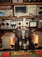
Hi guys, I designed an SE amplifier with 6S4S galvanically coupled with a special tube having the high amplification factor and slope in addition to the resistor in the cathode of 6S4S that ensures its negativity I replaced it with a constant current generator with the 6P3S tube set to provide the current of 60mA through the final tube. The results of the measurements after finding the optimal OT impedance are encouraging, very stable operation and at a mono listening the sound is above expectations
Attachments
![20241209_113825[1].jpg](/community/data/attachments/1298/1298946-121bde104f98289c92a64421acbc07af.jpg?hash=bsXMCiKY8O)

![20241208_184122[1].jpg](/community/data/attachments/1298/1298948-588b321abc6f9d537fb5e89e74c41685.jpg?hash=4sgNwmacOw)


The oscillogram was made only with the SQW signal injection output transformer in the secondary by means of an amplifier with transistors in class A and with the primary closed by a resistance equivalent to Zpgood job....10khz square wave..output of opt ?
I completed the electronic part of the amplifier but I gave up the tube from the cathode of 6s4s replaced with a 3.3k/50w resistor. The measurements are identical to those in the initial tests of the amplifier construction and the sound listened to on some Klipsch R820 speakers is beyond expectations, you can feel the advantage of galvanic coupling. It will be equipped with a wooden frame and the final adjustments
Attachments

![20250403_113223[1].jpg](/community/data/attachments/1353/1353636-ffc692e056500f0163353b2b56c7c9f9.jpg?hash=uWaDe195E-)

Hi
Just about 9,2H with 15cm2 core section.
With 1200 or 1300 turns, you must have about +- 20H.
So 1th, the numbers of turn is choice very small (help to get a good HF response)
2th the gap is too large
3th your measurement is reduced
Just about 9,2H with 15cm2 core section.
With 1200 or 1300 turns, you must have about +- 20H.
So 1th, the numbers of turn is choice very small (help to get a good HF response)
2th the gap is too large
3th your measurement is reduced
Member
Joined 2009
Paid Member
Nice project. I have thought about something similar (in my 2A3 thread) awhile ago but no progress! I was considering a 6V6 for the Cathode load. Unfortunately, I don’t think I have enough heater power.
The initial inductance measurements were made at a frequency of 300 Hz, at 50hz it results in 13.9H and the number of turns in the primary is 1980 turns. The frequency band of the amplifier measured on a load resistance at -1dB is 14Hi
Just about 9,2H with 15cm2 core section.
With 1200 or 1300 turns, you must have about +- 20H.
So 1th, the numbers of turn is choice very small (help to get a good HF response)
2th the gap is too large
3th your measurement is reduced
hz-88.6 Khz THD=2.7%/3.6w

Thinks for your answer
13.9H and 1980 trs seem's low to me .
What is the current for whitch the gap is adjusted
13.9H and 1980 trs seem's low to me .
What is the current for whitch the gap is adjusted
The anodic current is 60mA and for this I adjusted the input to 0.15mm, with 0.1mm the saturation manifests itself and with 0.2mm the inductance decreases to 10 H
so practically 0.15mm is a reasonable compromise. If you notice the minimum frequency played at -1dB is 14Hz but always the tubes with low internal resistance help the transformers, it seems hard to believe but that's it. If I were to lower the input to 0.1mm the inductance would increase to 19H but the bass tone would be affected
so practically 0.15mm is a reasonable compromise. If you notice the minimum frequency played at -1dB is 14Hz but always the tubes with low internal resistance help the transformers, it seems hard to believe but that's it. If I were to lower the input to 0.1mm the inductance would increase to 19H but the bass tone would be affected

Thanks yan24 for the information, indeed the transformer calculation program is elegant and precise, the differences between the one built by me and the calculated one are minimal, only the primary inductance and DC resistance differ
If the OPT maker use different permeability core, than -this- M6 material (used in this simulation), the induction may be different even with similar air gap.Take a look a OPT design assistant by Yves Monmagnon (very nice and clever tool)
SE amplifiers usually have an excellent behavior in reproducing mid and high frequencies, the harmonic distribution makes the difference between the SE and PP configuration, that's why I preferred to have a low loss inductance in the OT construction and the low frequency reproduction to be helped by the low internal resistance of the 6s4s tube. I recommend the construction of amplifiers with galvanic coupling even if there are certain reservations related to stability and safety, it is worth it, please believe me


- Home
- Amplifiers
- Tubes / Valves
- Direct coupled SE amplifier 6S4S+E810F