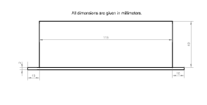
Based on the 100W 3-Way DSP Amp board, I made these modules on a plate radiator.
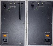
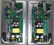
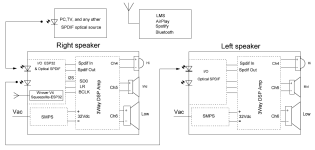
Performance parameter:
• Output power: 100 W per channel, R load = 4 Ohms.
• Speaker impedance: 4 - 8 Ohm (2Ohm – max 50W)
• Frequency response: 20Hz - 20kHz
• THD -3dB: less than 0.005% on 8Ohm load, and less than 0.01% on 4Ohm load
• SNR: 106dB(A)
• Spdif Input: 16-32bit 44.1-96kHz
• Spdif Output: 16-32bit 44.1-96kHz
• I2S Input: 16-32bit 44.1-192kHz
• Power supply: 100V-240V, 32V/11A
• Consumption power: Idle mode 12W, sleeping mode 4.5W
• Efficiency - 80%
More detailed parameters of the 3-Way DSP board can be found in this topic. https://www.diyaudio.com/community/threads/3-way-dsp-amp.415065/#post-7734899
The DSP board are flashed with a starter program called 3Way FIR 48kHz. The folder with the starter projects is attached to the message..
The plates come with a programmer on the CYC68013A chip and an optical receiver for remote volume control.
Those wishing to purchase such plates, write in private messages.
The price of the entire set is 370 US dollars.
Delivery to Europe and America is at my expense. Delivery to islands or other distant places is negotiated separately.
Payment via Payoneer.
Attachments
Last edited:
For those who want to make such plate amplifiers based on 3Way DSP Amp boards. https://www.diyaudio.com/community/threads/3-way-dsp-amp.415065/#post-7734899
Link to the power supply unit used 32V 11A. https://www.aliexpress.us/item/1005...st_main.5.ddff1802N2AJX9&gatewayAdapt=glo2usa
AC power Socket with light fuse https://www.aliexpress.us/item/1005...7w9Vo8XV&utparam-url=scene:search|query_from:
Antenna WiFi https://www.aliexpress.us/item/1005...ene:pcDetailBottomMoreOtherSeller|query_from:
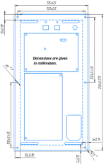
DXF file for laser metal cutting machine attached to the message.
Attachments
This is what the optical receiver of the remote control looks like.
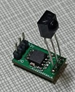
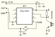
The remote control itself is not included in the package. You will have to use a universal remote control that supports the control protocol from the LG TV, or use the program on a smartphone that has an IR output.
I use the Remote Control program for Android to check the receiver.
The board has auxiliary ADC pins and 5V power supply pins, to which it is very easy to connect the sound level control board.
The board operates from 3.3V to 5V.
For example, I used ADC number 1 and 5V power supply, which is output to the board pins.
You need to be careful when connecting the optical receiver board, because if you apply the wrong polarity to the board, the microcontroller will fail.

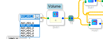
In order for the output of the optical receiver to control the volume level, it is enough to change the ADC0 input to the ADC1 input in the Sigma Studio project.


The remote control itself is not included in the package. You will have to use a universal remote control that supports the control protocol from the LG TV, or use the program on a smartphone that has an IR output.
I use the Remote Control program for Android to check the receiver.
The board has auxiliary ADC pins and 5V power supply pins, to which it is very easy to connect the sound level control board.
The board operates from 3.3V to 5V.
For example, I used ADC number 1 and 5V power supply, which is output to the board pins.
You need to be careful when connecting the optical receiver board, because if you apply the wrong polarity to the board, the microcontroller will fail.

In order for the output of the optical receiver to control the volume level, it is enough to change the ADC0 input to the ADC1 input in the Sigma Studio project.

This link isn't working right nowLink to the power supply unit used 32V 11A. https://www.aliexpress.us/item/1005...st_main.5.ddff1802N2AJX9&gatewayAdapt=glo2usa
https://www.aliexpress.com/item/100...eOtherSeller|query_from:&gatewayAdapt=glo2nld
Updated the link to the 32V 11A power supply.
Updated the link to the 32V 11A power supply.
It's odd, both links flash the product for a second then switch to this

I thought maybe I'm being geofenced so I set my vpn to Germany and even Lithuania but no difference 🤔
I thought maybe I'm being geofenced so I set my vpn to Germany and even Lithuania but no difference 🤔
I thought maybe I'm being geofenced so I set my vpn to Germany and even Lithuania but no difference 🤔
https://www.aliexpress.us/item/3256...ene:pcDetailBottomMoreOtherSeller|query_from:
Got it, it's most likely a location issue. I set up shipping to US and hopefully the link will open for you now.
This is a power 3-Way DAC with DSP ADAU1452, the settings of which are fully accessible via Sigma Studio.So it's more or less a DIY hypex FA123 without the ncore amps but also so farily cool extra IO options?
Access to DSP unties the hands of an experienced developer of multi-band speakers, and direct PWM synthesis and amplification of the PWM signal with feedback allows you to get rid of double conversion of a digital signal to analog, and analog to PWM, which also makes it easier to get an acceptable, unclamped sound at the output of this power DAC. The esp32 module with the Squeezelite 32-bit program allows you to organize 24-bit streaming using the LMS service. In general, if you do not need an analog input, and do not want to spend money on FA123, then these plates allow you to assemble a three-band active speaker system for a lower price.
Hypex FA123 retails for $557 (per channel!) in the US.
That seems prohibitively expensive for its relatively meager power.
That seems prohibitively expensive for its relatively meager power.
Plate DSP ADAU1452 Amp 3x100W is out of stock, I will inform you when the plates become available.
I'm new to this, so please be prepared for some strange questions...
a) Installed SigmaStudio 4.7, opened one of the startup-files "R 3Way subtractive 48kHz", pressed "link-compile-connect" and get a message from the compiler output saying :
Obsolete algorithm code encountered in this project:
http://wiki.analog.com/resources/to...astudio/buildingschematics/obsoletealgorithms
1. Cell: Lookup Table1_2, Algorithm: LUT w/Min and Max (8.24)
- Seems this is the look-up table for the volume control, does this function have to be updated?
b) When I look at the probe window and start stimulus, the output is like this :

Where is the response for the low-pass section?
It's a bump in the (green) summed output, why?
a) Installed SigmaStudio 4.7, opened one of the startup-files "R 3Way subtractive 48kHz", pressed "link-compile-connect" and get a message from the compiler output saying :
Obsolete algorithm code encountered in this project:
http://wiki.analog.com/resources/to...astudio/buildingschematics/obsoletealgorithms
1. Cell: Lookup Table1_2, Algorithm: LUT w/Min and Max (8.24)
- Seems this is the look-up table for the volume control, does this function have to be updated?
b) When I look at the probe window and start stimulus, the output is like this :
Where is the response for the low-pass section?
It's a bump in the (green) summed output, why?
Sigma Studio sometimes behaves very strangely, so the usual questions are quite common for those who start using Sigma Studio.I'm new to this, so please be prepared for some strange questions...
Yes, it looks like Sigma Studio wants you to update the table. Why it wants you specifically, I don't understand, because I have version 4.7 on Windows 10 and Sigma Studio doesn't ask to update the table algorithm.1. Cell: Lookup Table1_2, Algorithm: LUT w/Min and Max (8.24)
- Seems this is the look-up table for the volume control, does this function have to be updated?
Often the simulation does not draw one of the bands; to draw a band, it is enough to change one of the parameters in the band in which there is no display, for example, you can increase and decrease the delay line in the low-frequency band by one.Where is the response for the low-pass section?
This hump is associated with a non-optimal delay time in the low-frequency band, increasing the delay time to seven samples removes this hump.It's a bump in the (green) summed output, why?
I want to draw your attention to the fact that in this window we see the general electrical amplitude-frequency characteristic, then when we need to combine the acoustic centers of the speakers at the listening point, we will need to introduce a delay in the high-frequency and mid-frequency bands, which will ultimately change the electrical frequency response that we see in the simulation window. That is, this frequency response is the initial frequency response, which will ultimately not be a straight line in Sigma Studio, in other words, to get a straight acoustic frequency response, we need to make a curved electrical frequency response.
Thanks for Your quick response 🙂
Did a cleanup of my PC, reinstalled Sigma Studio (we use the save version) and tried again. Still the same message about obsolete algorithm, I dont care to much as long as it will do the job. Time will show.
The delay adjustment did the trick 🙂 (todays victory of man vs computer/SW)
I'm aware that the acoustic centers have to be on a curve to get correct impulse response in the listening position. I like the idea of being able to fix this with delays in software rather than with a saw. That leads to the next question :
- Is it possible to swap the (double precision 4th order LP) 24dB/oct Butterworth filters(q=0,707) with 24dB/oct Linkwitz-Riley filters(Q=0,5) ?
This will give -6dB sum at crossover frequency for a flat acoustic sum (Butterworth give a +3dB hump), and a perfect impulse response.
(Two series-connected Butterworth will behave like one Linkwitz-Riley (0,707x0,707=0,5) but might be an unneccesary high computing load)
- Could allpass-filters be used instead of time delays in the subtractive branches ?
N-th order allpass is supposed to have the same delay/phase response as N-th order filter
I understand you want to get such frequency response? The desired cutoff frequency is indicated in the end marked with an arrow.- Is it possible to swap the (double precision 4th order LP) 24dB/oct Butterworth filters(q=0,707) with 24dB/oct Linkwitz-Riley filters(Q=0,5) ?
This will give -6dB sum at crossover frequency for a flat acoustic sum (Butterworth give a +3dB hump), and a perfect impulse response.
I attached the file for Sigma Studio to the message.
I find it difficult to answer. You can try to find the answer yourself using Sigma Studio. It seems more rational to me to use a delay line.- Could allpass-filters be used instead of time delays in the subtractive branches ?
N-th order allpass is supposed to have the same delay/phase response as N-th order filter
Attachments
Thank You very much.
Wonder if the unused Hi-out functions in the 2w LR-block eat resources. Gess simulating might be needed to find out which filters uses less computing power, less power should give less noise. I will look more into the datasheet for ADAU1452 to try to find out.
- Tried the idea by changing the 3way subtractive 192kHz schematic, and the result seems to be as expected (I made an 2-way active analog version many years ago). A bit of phase offset from first branch of filters is seen in second branch output, crossover freq's are close.
A constant delay in the subtractive branch is frequency independent, and results in more phase difference with rising frequency.
Filters realized with second order double precision no slew general EQ.


LR sums nice at -6dB with 360 degree phase shift at crossover, for around 720 degree phase shift at Hi output, drivers can be connected in-phase and delay can be used to align the acoustic centers. Still, the result is not linear phase, but IFIR and the like will have to wait a bit....
I will simulate a adapted version with HP-filters to compare.
- As I understand, Your circuit is able to resample all input frequencies (44.1, 48....)
Is it possible and/or smart to use internal clock at 192kHz instead of 48kHz, or are there some reasons to keep the frequency low?
Wonder if the unused Hi-out functions in the 2w LR-block eat resources. Gess simulating might be needed to find out which filters uses less computing power, less power should give less noise. I will look more into the datasheet for ADAU1452 to try to find out.
- Tried the idea by changing the 3way subtractive 192kHz schematic, and the result seems to be as expected (I made an 2-way active analog version many years ago). A bit of phase offset from first branch of filters is seen in second branch output, crossover freq's are close.
A constant delay in the subtractive branch is frequency independent, and results in more phase difference with rising frequency.
Filters realized with second order double precision no slew general EQ.
LR sums nice at -6dB with 360 degree phase shift at crossover, for around 720 degree phase shift at Hi output, drivers can be connected in-phase and delay can be used to align the acoustic centers. Still, the result is not linear phase, but IFIR and the like will have to wait a bit....
I will simulate a adapted version with HP-filters to compare.
- As I understand, Your circuit is able to resample all input frequencies (44.1, 48....)
Is it possible and/or smart to use internal clock at 192kHz instead of 48kHz, or are there some reasons to keep the frequency low?
It is possible but you will have to change the settings in ASRC. Now when I transfer the project to 192 kHz, Sigma Studio stops processing the Slew vol block, and for the circuit to work, you need to delete it. There were no problems before. The ASRC settings can be found in the projects attached to the message.Is it possible and/or smart to use internal clock at 192kHz instead of 48kHz, or are there some reasons to keep the frequency low?
As I understand it, 192 kHz is important when you need to reduce delays when using a FIR filter, for IIR filters, as I understand it, there is no difference between 48 kHz and 192 kHz.
Attachments
I will simulate a adapted version with HP-filters to compare.
I implemented your proposal in Sigma Studio and it is more rational than the delay line.
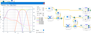
I converted the LR24 project to 192 kHz. It turned out that it was the table that prevented the volume control from working, I replaced the table with a standard one and everything started working as it should.Is it possible and/or smart to use internal clock at 192kHz instead of 48kHz, or are there some reasons to keep the frequency low?
I attached a file for Sigma Studio for 192 kHz. But now I don't know what delay is needed between the right and left channels for 192 kHz, you will have to find this delay yourself, I don't have now two boards to measure this delay.
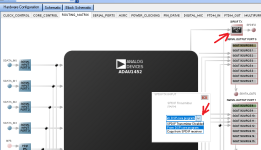
But if you don't need streaming via Wi-Fi, you can activate copying spdif from the receiver to the transmitter and then the delay between the right and left speakers will not be needed. In this case, I2S will only work on the right speaker and the left channel will not be able to get to the left speaker.
Attachments
Last edited: