Hello everyone,
So I am trying to build my first speakers, and I got stuck (obviously) with no idea why predicted crossover and real implementation is way out of acceptable range?
I will attach program I've used and response graph and photo ,of loose and glued implementation. I do hope for help. Thanks in advance
So I am trying to build my first speakers, and I got stuck (obviously) with no idea why predicted crossover and real implementation is way out of acceptable range?
I will attach program I've used and response graph and photo ,of loose and glued implementation. I do hope for help. Thanks in advance
Attachments
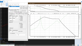


I'm interested in the toroids. Do you happen to have the schematic? How about overlayed measurements of with and without the crossover?


It's not easy to guess what's going on there but those inductors are not the right type for this. Not only are the cores the wrong material but common mode chokes will be limited when wired the wrong way. It's possible you're shorting the amp with the capacitor so I'd stop using them like that.
yikes what's up with the low passing? your effectively shorting to ground everything over a 1000 HZ....why? are you using a tweeter at all?
My suggestion is to simulate this all in XSim (simplest) or VituixCAD. Then break it in the simulator. 🙂
Last edited:
That needs some education...real implementation
first, the 0.5Ω resistor showed in reality it's just the DC resistance of the inductor. The inductor ...
Watch some pics of the crossovers (don't fall in the fancy category of flat foil coil) and you'll learn
Magnetic cores for speaker inductors must have a gap to have minimum linear behavior.
These toroids don't seam to have a gap. Do they have?
They get very non linear and will saturate very easily without gap.
I'm in favor of using iron/ferrite cores, but with air gap or the core being just a rod.
In addition, you need to know how much magnetic flux density you are applying to the core to make sure it is below the saturation level.
For ferrite, something below 0.2Tesla and for iron core below 1Tesla. The lower the better.

...VituixCad is a waste of time for me, as I have spent two weeks and gave up without even managing to put speakers in. That's why I used Basta, as suggested by someone... Now XSim. I already regret going this path, money spent, so no turning back. (exhausted daily after work trying all this...) 😢My suggestion is to simulate this all in XSim (simplest) or VituixCAD. Then break it in the simulator. 🙂


wow open baffle with a passive x-over that's not for the faint of heart...now i (sorta) get that filter!
so what is your driver compliment?
so what is your driver compliment?
The dip down towards 200Hz is not there without the crossover (post #3) and this doesn't make a lot of sense. I don't want to confuse two things at once but is this an open baffle design?
I wouldn't judge this until you have the crossover and room positioning sorted, so hang in there..
I wouldn't judge this until you have the crossover and room positioning sorted, so hang in there..
Yes, it is open baffle designe. I get a dip at 200hz if I leave mids in same polarity, but if I switch it gets gone. I can upload how it looks in same polarity. Also, I had room resonance at 35 hz, which would spike up all low frequencies to one 20db higher than rest spike, and I have tamed same with tuned low trap. Interestingly enough, now I don't have spike on ordinary boxed speakers, but I still get bigger low output on open baffle, and I think is good.
I have measured maybe three days in a row proper baffle placement, found nice continuous curve for midrange, but when I measure tweeters now - separately each chanel is perfect, but stereo gets bumps at 12k and 16k. Why is that? I thought it's too high to influence each chanel 2meters apart, and horn loaded...
I have measured maybe three days in a row proper baffle placement, found nice continuous curve for midrange, but when I measure tweeters now - separately each chanel is perfect, but stereo gets bumps at 12k and 16k. Why is that? I thought it's too high to influence each chanel 2meters apart, and horn loaded...
Got it, thanks. So I should place speakers symmetrically so not to have comb filter issues. Thanks
I too am designing crossovers for the 1st time. Vitiux was suggested to me after having what ended up beiong an error on my part. I went back to XSim. Vitiux is for people smarter than me. I couldnt get anything to load up most of the time and on the occasion I did, I fumbled around long enough to realize I needed to go back to XSim. My skills lie in woodworking
- Home
- Design & Build
- Electronic Design
- Crossover help