Presented here is my lastest DIY audio project. Actually, this is my 2nd preamp I've built using the base preamp PCB that was designed by my friend and fellow DIYer, Jan Hofland. This has turned out to be an ultra-quiet preamp board built around the OPA1656. It is stunningly quiet. More information about the PCB can be found over in this thread here. The preamp offers a lowpass subwoofer output, selectable at 80, 120 or 200Hz. In addition, it also offers selectable gain at 0, 6, or 12dB. I find with most of the inputs I use 0dB works just fine.
For this project I had a few objectives. Use the same model case I had used for an amplifier and streamer I completed last year. Integrate a new and improved(modernized) source selector, and add a Bluetooth adapter PCB.
The case is a Goodisory mini-ITX case. There was different mechanical casework, and 3D panels that required unique customization. The most exciting objective was met with my design(functional) of a 4-input pushbutton selector switch. Pushbutton selectors are not new, but I wanted one that did not use relays, or would make a noticeable click when changed. I also wanted to integrate a visual queue(LED) into the pushbutton itself indicating the active input. Another criteria was the switch needed to be small and operate with slight tactile feedback. After a bit of looking, I found the perfect little micro switch with built-in LED on Aliexpress. I also didn't want the switch module (PCB) to introduce any audible artifacts into the circuit. I turned to my designer friend and ran my idea by him. He was up for the challenge of designing a circuit board that would perform to my specs.
His final solution provided a nice, small PCB with no clicking added to the circuitry. And, as required for any audio application, the switch is silent, and does not add any noise to the switched input going to the output stage of the preamp. To get the pushbutton switch to integrate into the pre I had to put a couple jumpers on the pre board to force an 'unmute' function that was designed into the preamp PCB. And, for obvious reasons, I'm only using one of the original inputs for the output of the pushbutton switch PCB. All the RCA source connectors now wire directly to the silent switch PCB using MolexKK male headers.
Front side of Silent Source Switch(SSS)

The other feature I wanted to add to this preamp was to make it Bluetooth capable. Once again, Aliexpress to the rescue. I found this LDAC that was 5.3 compliant and seems to work as advertised. Now, I'm not under any allusion that Bluetooth provides a super quality audiophile experience - even with hi-res tracks. However, the latest LDAC Bluetooth standard sounds decent enough for casual or convenience listening. With 4 young adults children visiting from time to time(whom live by their cellphones) 🙂, this adds a nice touch to my system. I also have a DAP that I can now connect to this preamp with ease. It was an effortless experience pairing to my phone and DAP.
LDAC 5.3 Bluetooth module.

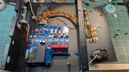
With my 2 major features met, I proceeded to assemble the preamp using my standard support hardware (remote switch and soft-start board). I also designed the back panel to accommodate the typical IEC inlet, and RCA jacks. This was then 3D printed and fitted to the case as shown. The most challenging part of the case work was fitting the pushbutton PCB to the front panel super-structure. I ended up using kind of a kludge solution, but it works. I used JB Weld adhesive to secure 6 brass standoffs to the inside front piece of metal. There is no binding at all on the little plastic switch covers, as there's essentially no travel depth of the switches. I had some practice using this technique with 2 other standalone switch-boxes I built. After much thought about internal layout, I decided on what is shown. I wanted to keep all the AC connections in the right-back corner. It was a tight fit for the IEC inlet, but doable as can be seen. To save space I've also adopted the method of raising my remote start PCB using standoffs. I've found that I can usually fit the PCB(remote start) using 2-3 standoffs anchored to the bottom, while a nylon standoff can easily rest on an open spot on the pre PCB. I've used this method in a couple other builds where horizontal space was limited.
In all, I'm pleased with the final result. It sounds great - as I've come to expect with Jan's designs - and the pushbutton selector is very functional, and cool. My next project will be to go digital with a UI - that has yet to be developed.


For this project I had a few objectives. Use the same model case I had used for an amplifier and streamer I completed last year. Integrate a new and improved(modernized) source selector, and add a Bluetooth adapter PCB.
The case is a Goodisory mini-ITX case. There was different mechanical casework, and 3D panels that required unique customization. The most exciting objective was met with my design(functional) of a 4-input pushbutton selector switch. Pushbutton selectors are not new, but I wanted one that did not use relays, or would make a noticeable click when changed. I also wanted to integrate a visual queue(LED) into the pushbutton itself indicating the active input. Another criteria was the switch needed to be small and operate with slight tactile feedback. After a bit of looking, I found the perfect little micro switch with built-in LED on Aliexpress. I also didn't want the switch module (PCB) to introduce any audible artifacts into the circuit. I turned to my designer friend and ran my idea by him. He was up for the challenge of designing a circuit board that would perform to my specs.
His final solution provided a nice, small PCB with no clicking added to the circuitry. And, as required for any audio application, the switch is silent, and does not add any noise to the switched input going to the output stage of the preamp. To get the pushbutton switch to integrate into the pre I had to put a couple jumpers on the pre board to force an 'unmute' function that was designed into the preamp PCB. And, for obvious reasons, I'm only using one of the original inputs for the output of the pushbutton switch PCB. All the RCA source connectors now wire directly to the silent switch PCB using MolexKK male headers.
Front side of Silent Source Switch(SSS)
The other feature I wanted to add to this preamp was to make it Bluetooth capable. Once again, Aliexpress to the rescue. I found this LDAC that was 5.3 compliant and seems to work as advertised. Now, I'm not under any allusion that Bluetooth provides a super quality audiophile experience - even with hi-res tracks. However, the latest LDAC Bluetooth standard sounds decent enough for casual or convenience listening. With 4 young adults children visiting from time to time(whom live by their cellphones) 🙂, this adds a nice touch to my system. I also have a DAP that I can now connect to this preamp with ease. It was an effortless experience pairing to my phone and DAP.
LDAC 5.3 Bluetooth module.
With my 2 major features met, I proceeded to assemble the preamp using my standard support hardware (remote switch and soft-start board). I also designed the back panel to accommodate the typical IEC inlet, and RCA jacks. This was then 3D printed and fitted to the case as shown. The most challenging part of the case work was fitting the pushbutton PCB to the front panel super-structure. I ended up using kind of a kludge solution, but it works. I used JB Weld adhesive to secure 6 brass standoffs to the inside front piece of metal. There is no binding at all on the little plastic switch covers, as there's essentially no travel depth of the switches. I had some practice using this technique with 2 other standalone switch-boxes I built. After much thought about internal layout, I decided on what is shown. I wanted to keep all the AC connections in the right-back corner. It was a tight fit for the IEC inlet, but doable as can be seen. To save space I've also adopted the method of raising my remote start PCB using standoffs. I've found that I can usually fit the PCB(remote start) using 2-3 standoffs anchored to the bottom, while a nylon standoff can easily rest on an open spot on the pre PCB. I've used this method in a couple other builds where horizontal space was limited.
In all, I'm pleased with the final result. It sounds great - as I've come to expect with Jan's designs - and the pushbutton selector is very functional, and cool. My next project will be to go digital with a UI - that has yet to be developed.
Attachments
-
 PXL_20250406_192238152.MP.jpg625.1 KB · Views: 37
 -
 PXL_20250406_192243511.MP.jpg516.1 KB · Views: 35
 -
 PXL_20250406_213228286.MP.jpg424.8 KB · Views: 33
 -
 PXL_20250406_221015075.MP.jpg577.3 KB · Views: 37
 -
 PXL_20250407_165628498.MP.jpg449.2 KB · Views: 36
 -
 PXL_20250408_010226201.MP.jpg421.2 KB · Views: 37
 -
 PXL_20241010_173419495.MP.jpg447.5 KB · Views: 35
 -
 PXL_20250406_213219542.MP.jpg556.2 KB · Views: 34
 -
 PXL_20250408_002445080.MP.jpg576.4 KB · Views: 35


There's also a headphone amp onboard, but I chose not to include in this particular pre. The Bluetooth works exceptional well and has no problem connecting, or staying connected. But, I haven't used it all that much yet.