Hi there,
First, excuse me for my poor English...
I plan to construct my first pair of multi-way speakers.
The total part price should remain below 200 €...
I started to work on it a weak ago and i would like your opinion.
First the speakers :
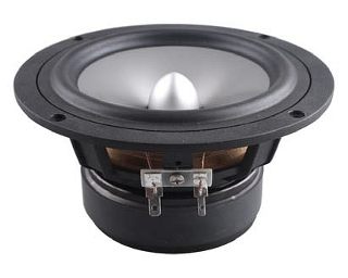
I choose for the mid-bass the Fountek FW146 : good T/S parameters, flat response low distortion low cost (about 30€), and good looking 😀

For the tweeter : SEAS 22TAF/G : hard aluminum/magnesium dome, flat response and ¾” dome (offset by a x-max off 0.25mm) so, good directivity . 33€


Then the filter :
I started by roughly simulate the impedance of each driver, it's not exactly the reality but it's better than nothing in my opinion...
Tweeter:
Woofer :
Then i started to design the filter, i choose a 2° order one.
After spending hours to try to optimize it, i think it's the best compromise. In fact the flattest i can do...
Now the funniest part, the enclosure :
I believe winisd for that : 10L @ 49Hz
And if i'm lucky, the final result will look like that :
If you have any comment advice or question please reply 🙂
First, excuse me for my poor English...
I plan to construct my first pair of multi-way speakers.
The total part price should remain below 200 €...
I started to work on it a weak ago and i would like your opinion.
First the speakers :
I choose for the mid-bass the Fountek FW146 : good T/S parameters, flat response low distortion low cost (about 30€), and good looking 😀
An externally hosted image should be here but it was not working when we last tested it.
For the tweeter : SEAS 22TAF/G : hard aluminum/magnesium dome, flat response and ¾” dome (offset by a x-max off 0.25mm) so, good directivity . 33€
Then the filter :
I started by roughly simulate the impedance of each driver, it's not exactly the reality but it's better than nothing in my opinion...
Tweeter:
An externally hosted image should be here but it was not working when we last tested it.
An externally hosted image should be here but it was not working when we last tested it.
Woofer :
An externally hosted image should be here but it was not working when we last tested it.
An externally hosted image should be here but it was not working when we last tested it.
Then i started to design the filter, i choose a 2° order one.
After spending hours to try to optimize it, i think it's the best compromise. In fact the flattest i can do...
An externally hosted image should be here but it was not working when we last tested it.
An externally hosted image should be here but it was not working when we last tested it.
An externally hosted image should be here but it was not working when we last tested it.
Now the funniest part, the enclosure :
I believe winisd for that : 10L @ 49Hz
An externally hosted image should be here but it was not working when we last tested it.
And if i'm lucky, the final result will look like that :
An externally hosted image should be here but it was not working when we last tested it.
If you have any comment advice or question please reply 🙂
you have great computer skills, im makig a pair of three ways, i like your modeling, looks better than my pen drawing with webcam pics.... you also seem fairly good understanding how to cross over speakers,
i must say that woofer looks good. however i must also say, that tweater looks like a piece of junk. i mean it has a hexagonal grill thing (bound to mess with the sound....even if not on paper....) but im sure you can remove it if needs be
what program are you using in the above illistrations? to design the crossover? thanks
also why is this speaker vented at the top and not the back? is there any sound advantage of this?
I'd cross the tweeter over higher, you're a bit close to it's resonance freq;
I have SEAS tweeters with the 'hexagonal grill thing' - no problem at all....
I have SEAS tweeters with the 'hexagonal grill thing' - no problem at all....
Last edited:
Hi,
Have a good read of the FRD tools links below.
Small speakers need baffle step compensation to sound balanced.
You should suppress the drivers metal cone break up peak.
Have a look at Zaphs metal cone designs for how to do that,
implement BSC and and generally hit acoustic x/o targets.
rgds, sreten.
undefinition (see if nothing else, the excellent FAQs)
The Speaker Building Bible - Thread opened for edits/input. - Techtalk Speaker Building, Audio, Video, and Electronics Customer Discussion Forum From Parts-Express.com
Zaph|Audio
Zaph|Audio - ZA5 Speaker Designs with ZA14W08 woofer and Vifa DQ25SC16-04 tweeter
FRD Consortium tools guide
http://web.archive.org/web/20090902124715/http://geocities.com/woove99/Spkrbldg/DesigningXO.htm
RJB Audio Projects
http://web.archive.org/web/20090902202231/http://geocities.com/woove99/Spkrbldg/
Speaker Design Works
HTGuide Forum - A Guide to HTguide.com Completed Speaker Designs.
A Speaker project
DIY Loudspeaker Projects Troels Gravesen
Humble Homemade Hifi
Quarter Wavelength Loudspeaker Design
The Frugal-Horns Site -- High Performance, Low Cost DIY Horn Designs
Linkwitz Lab - Loudspeaker Design
Music and Design
Great free SPICE Emulator : SPICE-Based Analog Simulation Program - TINA-TI - TI Tool Folder
@wolf_teeth thanks but what is Allen's Sticky ?
@WaVeInFoRm you are right for the tweeter but i'm not sure that removing the grid will really enhance the sound, may even be there to tone down some resonances of the tweeter...
For the soft i use qucs for the elec and solidworks with photoview360 for the illustration.
The speaker is vented on the top simply because the vent length is about 28cm and then it's too long to be on the front.
and keep doing your pen drawing it's not as clean but it's much more funny ^^
@ PeteMcK I know that it's very close but in fact i want to be as close as possible of the line array configuration at the cross-over frequency.
Thanks to sreten i found that http://www.humblehomemadehifi.com/download/Humble%20Homemade%20Hifi_Extremon_copy.pdf
they cut the same tweeter at only 1750Hz... so 2K it's not that bad finally.
@sreten thak you to speak about baffle step, i didn't know this problem 🙁 i have to work on it.
For the metal break up peak i think it not will be audible because it's rejected to -35 db with my cross-over and then -35dB(filter)+15dB(peak) is -20 and then on the graph -20dB+0dB= about 0.25dB
Last edited:
@wolf_teeth thanks but what is Allen's Sticky ?
Hi,
Its pretty much the FRD tools stuff I provided links to. I prefer my links
because whilst not wrong the sticky about speaker simulation treads
the zobel eveything path which isn't necessary most of the time.
http://www.diyaudio.com/forums/mult...designing-crossovers-without-measurement.html
rgds, sreten.
Last edited:
For the metal break up peak i think it not will be audible because it's rejected to -35 db with my cross
-over and then -35dB(filter)+15dB(peak) is -20 and then on the graph -20dB+0dB= about 0.25dB
Hi,
Probably right but it doesn't do any harm to look at the options.
A cheap highish resistance air core and capacitor across the
driver isn't expensive and can work with a single BSC inductor,
see Zaph's L18 design for the general gist of the approach.
The real issue is the peaks effect on distortion profiles and crossing
the bass/mid as low as possible for this reason is a good idea.
Note that you need to target the final acoustic x/o and slopes,
not electrical filter targets, though your doing far better than
most in modelling the driver impedance profiles. There are
other ways of doing it as described in the FRD tools links.
(zma files for impedance rather than equivalent models,
frd files for the drivers measured for given circumstances.)
rgds, sreten.
Last edited:
Hello !
This is my last simulation with the real speakers spl charts
i will not correct the baffle step because it's very balanced by the room gain for me (the enclosure will be right against a wall :/ )
It's not as good as i thought but but i will do with it...
If the result is bad i will correct it with the exelent JAMin equalizer while i know the response of the speakers
Attachments


- Status
- Not open for further replies.
- Home
- Loudspeakers
- Multi-Way
- 2-way bookshelf speaker