
I have built Apex retro in the past but i want to make a low duty amp for my desktop speakersWhy not Apex retro?
The Apex retro (I assume the 50W design) is very retro. Here are some points to start with:
1. 2N3773 output transistors are very slow-worse than the old2N3055 (now H), with ft (min) of 200kHz. Not recommended, but the TIP41/42 are faster epi (3MHz) and OK.
2. The lower output stage can latch up. The key to avoiding this is to limit the current to the stage. One way to do that is to use a PNP VAS, so that the bootstrap resistors are on the low side, not high side.
3. Feedback from the LS is undesirable. ALthough this may have reduced distortion from the output capacitor, it can cause clipping at LF below the normal cut-off frequency. This degrades the signal at high output powers and low frequencies, that it is better to simply use feedback from the output rail and let the output capacitor roll off the frequency response. But at VLF square waves it will give a differentiated signal, though this may not be distinguishable acoustically (a square wave and its differential contain plenty of odd harmonics).
Modern capacitors generally have low impedance (inductance and resistance) and won't cause significant distortion, although sometimes they can (look up capacitor distortion).
4. Miller stabilisation does not help to reduce crossover distortion.
Last edited:
Or build the well documented, superb sounding, and fully tested Ranchu-Aksa Quasi.
Very simple quasi complimentary MOSFET amplifier
Very simple quasi complimentary MOSFET amplifier
1. 2N3773 output transistors are very slow-worse than the old2N3055 (now H), with ft (min) of 200kHz. Not recommended, but the TIP41/42 are faster epi (3MHz) and OK.
Depends on the 3773. On Semi 3773 and any of the myriad of 2nd source versions (Central, NTE, etc) are 4 MHz. The spec still says 200kHz, but the typical curves show 4 MHz. If you found an old RCA it might be the slower version, but in the 80’s GE/RCA/Harris switched over to epi-base too.
The On Semi 3773 is practically indistinguishable from an MJ15003. Today they are probably the same exact thing, tested to a different spec.
TIP 41 are just fine up to about a 48V supply. (+/- 24 in split rail terms). There is always the 33 or 35 if you want to go above that or run lower impeadances. Always just buy the 100 volt C version. They don’t cost any more.
Try a decent, fast audio transistor for outputs. Quasi-complementary designs can sound a lot better when the crossover switching is cleaner and using a single pair of old slugs for power transistors doesn't help with the sound quality we likely expect to hear now. Perhaps you want that olde worlde sound? Fine, but I'd begin by considering 30MHz 2SC5200 and think upwards from there.
5200’s are available in TO-220 - the Fairchild version is. There is also the MJE15030, which makes a fine low power output device. If you’re really wanting TO-220’s.
It's cheap to buy this LJM which is quasi and developed as alternative for high power audio ICs:
MX40 100W+100W 4ohm stereo Class AB Power amplifier completed board by LJM-in Amplifier from Consumer Electronics on Aliexpress.com | Alibaba Group
MX40 100W+100W 4ohm stereo Class AB Power amplifier completed board by LJM-in Amplifier from Consumer Electronics on Aliexpress.com | Alibaba Group
wg-ski, yes, I agree that the old slow devices are unlikely to be found these days, but at least RCA had the decency to change the spec. and name of the 2N3055 device.
Engineers usually work with specs as well as typical data, but OEMs could always agree a spec with the transistor manufacturer, but possibly end up with a custom part number.
I've used 3773's in PSUs, not amps, but I'd spec. an MJ15003 in preference. Think ON Semi could probably change the spec on a number of the old devices (2N3442 perhaps? 2N3772?)
Last edited:
I must say I find some attitudes here disappointing. This is DIYAudio, not "build a kit audio". I'm not against using other people's designs but I am against discouraging people to have a go at their own designs, which is clearly maouna's goal.
There are many reasons to build something that can just as easily be accomplished by simply buying an LM3886. Most of them good ones. Amps like this can often be built using only what is on hand - requiring no order to Mouser or any expenditure whatsoever. The transistor you have my not offer the highest possible performance, but who cares if they are free. And if you want to spend five bucks on parts and fifteen on freight to improve it that’s up to you. They are also fun little projects. And necessary stepping stones to building the big ones. This is where you start if you want to make your first discrete amplifier - not building a Leach amp or Symasym.
I've used 3773's in PSUs, not amps, but I'd spec. an MJ15003 in preference. Think ON Semi could probably change the spec on a number of the old devices (2N3442 perhaps? 2N3772?)
I think they kept the same part # and spec because their parts would meet (exceed) the original spec, and could be used anywhere the original RCA version could. With the same spec and part number, they could be substituted in a next higher assembly BOM with minimal changes to documentation - just another vendor for the “same” part. Doesn’t always work the other way around - if an amp design (especially a complementary) requires the Motorola part, it would have to be documented as such.
I have used the Motorola/ON 3773’s in many amps over the years - both new and as substitutes for unobtainium parts. In both Quasi and full comp. in complementary I have paired them with 2N6609’s, MJ15004’s, MJ15016’s and even 2N6031’s. I have also used the old RCA hometaxial units - but only in vintage style same sex amps and of course power supplies. I still have a few of them, if I ever run across something for which they are uniquely suitable.
there are some points to consider.
Feedback from the output: this was common in the early days, but as your amp is capacitor coupled, this has an adverse effect at low frequencies and high volumes. If you are able to simulate this (there are some freebie simulators around, a lot here use LTspice) you can see the effects. The solution is to use feedback only from the output rail and rely on the capacitor having a low distortion.
Temperature stability: your feedback resistor controlling the DC point consists of a 10k and 33k split. As the VAS (2sc2240) warms up it will reduce Vbe by about 2mV/C, which will be amplified by the ratio of the feedback resistors to the 1k base. So you may see about 14mV/C drift. For a capacitor coupled amp this is not critical, but is is higher than desirable. Solution is also to use a lower feedback resistor directly from the output rail.
Quasi Original as posted
Dear all,
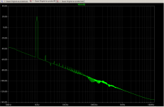
I took the liberty of simulating the original as posted at #1 as an exercise and obtained the following figure. Is it OK?
At #5, john_ellis commented :
--gannaji
Dear all,
I took the liberty of simulating the original as posted at #1 as an exercise and obtained the following figure. Is it OK?
At #5, john_ellis commented :
" 2. The lower output stage can latch up. The key to avoiding this is to limit the current to the stage. One way to do that is to use a PNP VAS, so that the bootstrap resistors are on the low side, not high side."
How to sim for this effect ? Is using PNP VAS the only solution ?
--gannaji
Attachments
Last edited:
Emitter resistor in the vas, base stopper on the CFP. Either/or/and. If you were going to add current limit transistors you pretty much have to.
The only way to sim for it is to have accurate models - for the exact transistors you have. Just grabbing any old model because it is on hand may or may not show it, or show a false positive when the real one won’t do it. The whole phenomenon has to do with what happens when the transistors saturate heavily. Sometimes you just get lucky and have no difficulty without trying, and that’s one reason certain transistor combinations got used heavily back in the day when these amps were common.
The only way to sim for it is to have accurate models - for the exact transistors you have. Just grabbing any old model because it is on hand may or may not show it, or show a false positive when the real one won’t do it. The whole phenomenon has to do with what happens when the transistors saturate heavily. Sometimes you just get lucky and have no difficulty without trying, and that’s one reason certain transistor combinations got used heavily back in the day when these amps were common.
Retro Nytech Amps
If you really want to go retro why not have a look at some of the old Nytech designs? They worked very well and had some interesting features.
Any suggestions or something to improve?
If you really want to go retro why not have a look at some of the old Nytech designs? They worked very well and had some interesting features.
Attachments

I usually use an emitter resistor on the VAS with two diodes to clamp the base voltage. Current limit is set to about 2.5x normal, but swapping the input and VAS around for their opposites tends to give the best results.Emitter resistor in the vas, base stopper on the CFP. Either/or/and.
- Status
- Not open for further replies.
- Home
- Amplifiers
- Solid State
- 30Watt Quasi amplifier schematic