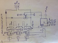
Sorry for the bad quality of the sketch, starting with Edraw today!
Features:
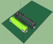
- standard 18650 protected cells, no custom bags
- up to 4000mAh
- 3S/6S (serial wiring allowed)
- relay switching between charging and listening for full galvanic isolation
- cheap single cell Li+/LiPo/LiFePO4 charger IC
- charging current up to 1A, default 350mA (one resistor)
- single +5V charging and working voltage only
(without cell: 1 holder + 1 relay + 1 IC + PCB + chickens chickens = 8.5$/cell )
What do you think, comments welcome!
P.S.: is LiFePO4 with protection available?
JP
Features:
- standard 18650 protected cells, no custom bags
- up to 4000mAh
- 3S/6S (serial wiring allowed)
- relay switching between charging and listening for full galvanic isolation
- cheap single cell Li+/LiPo/LiFePO4 charger IC
- charging current up to 1A, default 350mA (one resistor)
- single +5V charging and working voltage only
(without cell: 1 holder + 1 relay + 1 IC + PCB + chickens chickens = 8.5$/cell )
What do you think, comments welcome!
P.S.: is LiFePO4 with protection available?
JP
Attachments


A couple thoughts from someone who does Li-Ion battery technology for a living...
Why the complication of using 5V to charge the cells individually and relays to put them in series instead of using a higher supply voltage and charging them in the 3S or 6S configuration?
"Protected" 18650s are usually 3-5mm longer thane 65mm, so make sure they still fit your cell holder.
The cells are not going to be 4000mAh, at least not under any normal standard capacity testing.
I'm not aware of any protected LiFeP04 cells, but if you don't need the energy denstiy of standard Li-Ion chemistries they are a very good choice due to their increased stability, higher power output, and cycle life. You could use those cells and put the protection on the PCB.
Hello @jc2
Power on:
- only micros are powered (modification to apply to the architecture: +5V supply micros dedicated and +5V supply with external power on for chargers for example E/PS 800 series type)
- secondary controllers informs master controller over I2C about all single cell voltages: master controller don´t release voltage to loads until all batteries charged
- relay switching for fully galvanic isolation: charger is then in standby
- simplest discrete opto-isolated NAND over all voltages inform master controller about UV
5V supplies are commonly available (no specific needs for CC/CV charger, ok, MEANWELL goes cheap) and I don´t need balancing using cheap single cell charger IC´s: the micro will do the job by removing charger voltage from full charged one also informs the master controller upon specific default battery: UV and OV protection inside battery.
I´ll check the datasheet for the Keystone 18650 batterie holder and the datasheets of protected Li+/LiPo 18650 batteries.
I know about LiFePO4 and would really use them if protected available.
No protection:
- protection IC? single cell? TI, SEYKO, others? Mainly for Li+/LiPo!
- serializing needs balancing and produce heat...
I know the Endless Sphere DIY BMS old development, discovering today cell logs.
It´s my starting point and only fools never change their mind...
JP
1) I will check tomorrow availability for Silan SC8201 (LiFePO4 protection IC SOT23-6)
2) BMS protection schematics available on Endless Sphere
3) Checking charger IC from Linear Technology
JP
2) BMS protection schematics available on Endless Sphere
3) Checking charger IC from Linear Technology
JP
Sorry got a bit busy and forgot to check back.
TI probably has the biggest selection of charger, protection, and fuel gauge ICs. They have options for LiFePO4 cells. Many of the FG chips will have built in balancing which works quite well.
I think you could meet your requirements even when charging in series, and simplify things significantly. Even if you wanted to stick with a 5V power supply there are chargers that will charge 3S from 5V. Look for NVDC Buck boost charger, Intersil has one that I have used (ISL9237).
Without knowing exactly your design criteria it's hard to give any more specific recommendations.
Hello jc2,
Thanks for the informations. I know the TI, LT or Intersil part, very nice but they´re connected permanently over the battery pack.
First requirement: only UV protected batteries connected to load, means, protection switchs to balanced charging circuitry; should be realized with simplest optocoupled wired NAND connection to µC.
Serialized balanced charging, because of different battery behaviour (48S), will waste power and produce undesirable heat.
I´m working on the requirement specification.
I´ve found HYCON HY2112 1-Cell LiFePO4 Battery Packs Protection ICs and HYCON HY2212 1-Cell LI+/LiPo (could be used for LiFePO4) Battery Charge Balance IC: I´ve to check availability and to check distorsion of protected/unprotected batteries (Protection using Oscillator, Counter and Logic).
COTS 48S LiFePO4 charger coming from China.
Investigation done for Super Capacitors, but there are very expensive and need also specific charging and balancing, but nice for low power supplies (I/V Converter) and limited listening time: I´ve use this technologie for airborne UPS (Windows safety shutdowns).
A long weekend in prospect...
JP
Hi JPS64,
I've just briefly read through the thread and wonder what you will be using the LiFePO4s for? Personally I use LiFePO4s (123systems) but have connected them in a float mode (constant charging at ~3.4 VDC) which allows the immediate power delivery capability of the batteries to be directly connected to the circuitry in question and also makes sure that the circuitry is thermally stabilized due to constant voltages (This obviously does not work if you are working on a project with a commercial scope).
Additionally, when reading on "batteryuniversity's" webpages there are two (main) aspects that tend to reduce Li-ion (i.e. Li-ion - don't know if it also applies to LiFePO4 types) batteries' lifespan: one is charging the batteries to their maximum voltage (and keeping the voltage there), the second is high temperatures.
To this end: As far as I can see all of the battery protection devices that have been mentioned here cannot be set to a lower voltage than 3.6 VDC (Hycon).
Well, a few comments that popped up.
Good luck with your design ;-)
Jesper
Hello Jesper,
thanks you for the repply and your comments.
I´m reading a lot of application notes and technical papers, also old VDE norms. This information flows into my requirement specification.
For me, today, considering a N x S battery pack, technology independently:
- intended to be used for DACs and solid state preamplifiers (power amplifier and tube amplifier needs ogoing investigation)
- overall ored UV protection (2V, 2.5V or other voltages, peu importe) which enable charging
- single cell 1/10C charging (many ICs with charge management for all chemistry available, needs +5V and allows using standard pack external power supply such as ATX to avoid thermal problems during charging and thermal problems with balancing circuitry)
- master control µC (Atmel, USB bootloader)
- 5€/batterie overall costs
P.S.:I don´t want to do a commercial product
Jean-Paul
ricoh and rohm have voltage detectors and ic protectors for lifepo4 voltage like 3.6V.
I thought of an active flyback balancer per cell using a pcb style planar core transformer. a silego circuit could do the managment, pwm and fet drive, possibly helped by an accurate low power voltage detector.
I thought of an active flyback balancer per cell using a pcb style planar core transformer. a silego circuit could do the managment, pwm and fet drive, possibly helped by an accurate low power voltage detector.
Hello @basreflex,
thanks you for reply, I´ll show what Ricoh and Rohm are proposing and check the availability then most of this ICs are for volume production.
The "DIY" solution needs to be safe and as simply as possible.
... ongoing, after a lot of coffee and more cigarettes: sketching the first stand alone prototype intended to be used with headphone amplifier such as Cmoy, SOHA or other JFET ones:
- 5S (60x75mm)
- starting with 14650 (< 4Wh) protected Li+ or LiPo
- Microchip charging ICs (800mA 1C charging current)
- standard +5V wall-cube power supply
Relay or Mosfet switches, Mr. Watson?
JP
why use protected cells ?
the charger takes care of the overvoltage and charge current, you only need an undervoltage switch and that could be on the 5S voltage/ supply line. overcurrent can be done using a PTC or self resetting fuse. these cells have plenty capacity to turn off a fuse..
basreflex
the charger takes care of the overvoltage and charge current, you only need an undervoltage switch and that could be on the 5S voltage/ supply line. overcurrent can be done using a PTC or self resetting fuse. these cells have plenty capacity to turn off a fuse..
basreflex
@basreflex
Thanks for the information about resettable fuse or PTC, I will consider this important point: any SMD type recommendation?
I´m wrong assuming that the protection includes overcurrent protection?
With protection I don´t care about UV, battery is disconnected and supply voltage is losed, information to user that is time to charge the pack (perhaps one status light off LED).
User plugs the wall-cube and batteries are switched to N single cell chargers who manages the CC/CV charging with UV and defined constant current 1C: some simple glue logic indicates to the user the end of charge of all N single cells (LED, AND logic wiring? MCP73830 going in standby after charging).
Power off the wall-cube after charging to listen for music...
JP
internal cell protection is usually set near 5C as these cells are also used for e-cigarettes. it seems more suitable to size the PTC to the max current of your load to avoid pcb traces being vapourized on an accidental short.
use some margin like 3x as otherwise (ambiental) heating reduces the life of the PTC and lowers the trip threshold.
a good idea to place the PTC somewhere halfway the cell series connections , so you are allowed to short it on the PCB entry point.
there are many fuses both TH and smd from littlefuse for example. always check the trip points at various ambient temperatures.
basreflex
PS opto isolated Mos switches are a nice replacement for relays..

- Status
- Not open for further replies.
- Home
- Amplifiers
- Power Supplies
- 3S/6S Lithium Battery Pack