In the end this is what I built ... transients tested and listening tests ... it sounds fine (soon I will post a small video of the horrific creature). I hope I didn't make any mistakes in transcribing it to TinyCad.
Write me if you have any questions, suggestions or complaints ...
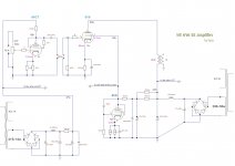
(WRONG SCHEMATICS!)
(the right schematics at #3)
Write me if you have any questions, suggestions or complaints ...
(WRONG SCHEMATICS!)
(the right schematics at #3)
Attachments
Last edited:
Good to see that you finished this project.
I assume the 6V6 has to function like a ripple killer. I would think for it to function properly, the topside of the 680 nF capacitor has to be connected before the 3K3 resistor instead of after it, like it is now. But maybe this is a drawing mistake in the schematic?
I assume the 6V6 has to function like a ripple killer. I would think for it to function properly, the topside of the 680 nF capacitor has to be connected before the 3K3 resistor instead of after it, like it is now. But maybe this is a drawing mistake in the schematic?
Good to see that you finished this project. 🙂
I assume the 6V6 has to function like a ripple killer. I would think for it to function properly, the topside of the 680 nF capacitor has to be connected before the 3K3 resistor instead of after it, like it is now. But maybe this is a drawing mistake in the schematic?
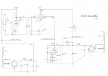
In fact there was a transcription error...
Are you there now?
Attachments
Last edited:
I meant the 680 nF capacitor between pin 5 and pins 3+4 of the 6V6 but by now I doubt if my earlier post was correct, so just forget about it.
I like the 6Y6's. They look a bit bigger than I expected.
I like the 6Y6's. They look a bit bigger than I expected.
I meant the 680 nF capacitor between pin 5 and pins 3+4 of the 6V6 but by now I doubt if my earlier post was correct, so just forget about it.
I like the 6Y6's. They look a bit bigger than I expected.
6V6 works as voltage regulator (135v needed) and current shunt. It should work more or less like a cold cathode voltage regulator.
6AC7 it is a good alternative to 1/2 ECC88 with a slightly higher Ri and a consequently slightly higher gain. The output resistance in this circuit is approx. 5k quite acceptable.
Those are 6Y6Gs and they are much bigger ... the 6Y6GTs are as big as the 6V6.
For 300-400$, plus the expense for a metal chassis, you can have a good 5w tube amplifier. It also has the convenience of being able to be used separately as a pre or power amplifier.
What i used:
Tubes = 2 Sylvania 6Y6G + 2 RCA VT112/6AC7 + 1 Russian 6P6S (6V6GT) = 30$
Power Transformer 6Y6G-6P6S = Chinese 150V-200V-230V/250MA+6.3V/4A = 50$
Power Transformer 6AC7 = 215v+6.3v from an old radio
Output Transformer = Wharfedale W12 * = 100$
Filter Chokes = 2xHammond 158SA (1H 240mA)= 20$
Big Elko Caps = Wima-Roe-Philips-Siemens = 30$
Polipropilene Caps = Arcotronics-Ero = 10$
Metal, vintage carbon and ceramic resistences = 20$
6 RCA plugs = 20$
* Wharfedale W12 = it is often considered as a PP OT, but the instructions do not specify it, on the contrary it speaks about 3 different Secondary Ratios.
Last edited:
There is only one thing that I just don't understand: because on the last capacitor of the preamp power supply there always remains 30v ac. even when the appliance is switched off.
You could place a bleeder resistor of 1M parallel to the 100 uF capacitor. This will let the capacitors in the preamp power supply discharge themselves after switch off.
You could place a bleeder resistor of 1M parallel to the 100 uF capacitor. This will let the capacitors in the preamp power supply discharge themselves after switch off.
I'll do it, tks.
I'd like to understand why... I have some doubt with 16u cap which Is used.
6V6 works as voltage regulator (135v needed) and current shunt. It should work more or less like a cold cathode voltage regulator.
One of the advantages of the shunt regultaor is that, using on the bias of the shunt regulator a 100 ohm resistence with a pot 500 ohm in series, it is possible to test and use all the most common pentodes, such as 6F6, 6K6, 6L6, 6V6, 6W6 and the European EL34, EL84 and EL95, and then adjust the correct screen voltage with a tester. For the function it performs, the tube should last a very long time.
I'm interested in trying out this project, as I find myself with several NOS Ken-Rad 6Y6 tubes. In the 1950's / 60's the 6Y6 run ultralinear with Acrosound 320 iron got rave reviews, also peaking my interest here. That was a PP, I'm wanting to stay SE. From a Newby would it be a great leap to modify the power stage of this circuit for SE/UL? I see that the voltages are right from the data sheet. To come up with an UL version of this circuit would I simply move the screen to the UL tap through a resistor that gets the screen back to 135V? If someone with more knowledge than I have can guide us through a UL mod for this amp it would be a great help.
Last edited:
In the meantime I have slightly modified the design using 2H chokes instead of 1H and a bypass cap on 6AC7, thus eliminating any kind of NFB ... it sound better and very satisfyingly.Sono interessato a provare questo progetto, dato che mi ritrovo con diverse valvole NOS Ken-Rad 6Y6. Negli anni '50 l'ultralineare da corsa 6Y6 con ferro Acrosound 320 ricevette recensioni entusiastiche, suscitando anche il mio interesse qui. Quella era una PP, voglio rimanere SE. Da Newby sarebbe un grande salto per modificare lo stadio di potenza di questo circuito per SE/UL? Vedo che le tensioni sono giuste dalla scheda tecnica. Per trovare una versione UL di questo circuito, sposterei semplicemente lo schermo sul rubinetto UL attraverso un resistore che riporta lo schermo a 135 V? Se qualcuno con più conoscenze di me può guidarci attraverso un mod UL per questo amplificatore sarebbe di grande aiuto.
As for UL, I hope you get the answer from those who know more than me. In any case, you will have to replace the cathode resistance on 6v6 with the right value, and not a simple undertaking because a few more or less are enough to change the result... or opt for a simpler solution as you wrote.
6Y6 is however a very musical tube, born specifically for audio amplification. It was abandoned because it has that particular V / mA ratio.
Thanks aria,
I'm hoping to get a discussion going around simply how to convert the OPT and 6Y6 to be UL, nothing more. So leaving the shunt power supply out of the discussion, assuming it can be any kind of power supply that can provide the voltages. As for the input stage I understand how to mod that or even replace it with a different tube entirely.
I just need a lesson on how to modify this output stage to be UL. Hoping its just some reconnections and a resistor or two.
Thanks aria,
I'm hoping to get a discussion going around simply how to convert the OPT and 6Y6 to be UL, nothing more. So leaving the shunt power supply out of the discussion, assuming it can be any kind of power supply that can provide the voltages. As for the input stage I understand how to mod that or even replace it with a different tube entirely.
I just need a lesson on how to modify this output stage to be UL. Hoping its just some reconnections and a resistor or two.
In the end there will be little left of the initial project, except the idea of using 6Y6.
I think we need others to chime in, the dedicated 6V6 shunt screen supply may still have a place elsewhere!In the end there will be little left of the initial project, except the idea of using 6Y6.
In the end there will be little left of the initial project, except the idea of using 6Y6.
Change of plans, I do want to keep the 6V6 shunt too, it is too nice to drop just because I wanted to try UL. I can do this by implementing both your pentode arrangement here, with an ultra linear switch that simply moves the screen over to the UL tap through a series resistor to drop the screen voltage back down to 135V. This would give switchable UL or pentode topology. I have both 5K and 3.5K SE/UL transformers to try out and a 3.2k Toroidy OPT (Poland). Thanks for bringing this here aria, I'm sure it sounds great. It follows the data sheets, and all the 6Y6 schematics I've found use the same operating points, so it must be proven. Even the well regarded 1955 Acrosound 320 6Y6 PP Amp is at the same operating points. Should be foolproof.
About the plan for SE UL using a resistor to drop the screen grid voltage to 135 V:
According tot the datasheet for the 6Y6 the screen grid current is 2.2 mA at zero-signal, and 9 mA at maximum signal. The voltage on the UL-tap of the OPT will be about 223 V.
To drop 223 - 135 = 88 V at 2.2 mA you would need a resistor of 40K (R = V/I = 88/0.0022 = 40000). But this 40K resistor will create an enormous sag when the 6Y6 is driven with signal. For every mA extra of screen grid current, the screen grid voltage would drop 40 V. I don't think this is going to work properly. The maximum output power will drop dramatically for sure. And I think it will also create distortion.
About the plan for SE UL using a resistor to drop the screen grid voltage to 135 V:
According tot the datasheet for the 6Y6 the screen grid current is 2.2 mA at zero-signal, and 9 mA at maximum signal. The voltage on the UL-tap of the OPT will be about 223 V.
To drop 223 - 135 = 88 V at 2.2 mA you would need a resistor of 40K (R = V/I = 88/0.0022 = 40000). But this 40K resistor will create an enormous sag when the 6Y6 is driven with signal. For every mA extra of screen grid current, the screen grid voltage would drop 40 V. I don't think this is going to work properly. The maximum output power will drop dramatically for sure. And I think it will also create distortion.
Thanks a lot for this info. This is why I'm a newby! Looking at some old schematics for this tube it was mostly used as PP, screen was hooked directly to the UL taps. I did find some other schematics for SE/UL from DY'ers that used a 40-50k resistor, thats where I got the idea to do this. Looking at the data sheet again, it doesnt name a max G2 voltage, so perhaps I can use a direct hookup to the UL tap (just like the old Acrosound 320 amp did, but for SE? Or maybe experiment with some very small resistors under 1k. I was thinking the g2 had a max voltage. If it can run ok with direct hookup to the screen taps in PP, it should be ok like that in SE right?
https://frank.pocnet.net/sheets/127/6/6Y6G.pdf
The old 1955 Acrosound 320 with 6Y6 (this is the amp that was well regarded back then) Of curse thats mainly due to the Acrosound.
From the datasheet I deduce that At Va = 200 V, Vg2 = 135 V and Vg1 = - 14 V, the value of the cathode resistor would be something like 200 to 220 Ohm. In the Acrosound amplifier the value of the common cathode resistor is 250 Ohm, which would 'translate' to 500 Ohm for only one 6Y6.
The fact that Acrosound amplifier was running the 6Y6's well over the maximum voltages must be proof of their capability to withstand this (an other example is the 12A6). But the current with no signal can't be that high (in view of the maximum anode dissipation) and I think this amplifier runs in Class AB. I would think that if you 'translate' these conditions to SE, so to Class A, the output power will be relatively low.
Just my thoughts.
- Home
- Amplifiers
- Tubes / Valves
- 6Y6 SE amplifier - Definitive project