
I'm attempting to develop something like that with a 5k transformer. I'm starting a line of experiments to prove this idea out. It will use plate-to-grid feedback on the output tube to reduce the output impedance at the tube plate (since these are high plate resistance tubes).
You can follow my experiments here. I plan on replacing the op-amp/mosfet input stage with a tube stage that accomplishes the same purpose and replacing the 6384 tube with a high-impedance transmitting triode like the 811A.
You can follow my experiments here. I plan on replacing the op-amp/mosfet input stage with a tube stage that accomplishes the same purpose and replacing the 6384 tube with a high-impedance transmitting triode like the 811A.
Even with much higher plate voltages than 500V, you will still need to drive the 811 with (partly) positive input signals. So your driver should be able to deliver the power to deal with the gridcurrent that will occur because of the (partly) positive drive.
If I understand it correctly, for audio it is best to insure that the 811 is biased positive enough so to prevent part of the input signal going negative. Otherwise the 'switching' between positive input signal (grid current occurring) and negative input signal (no grid current occurring) will create nasty high-order harmonics.
If I understand it correctly, for audio it is best to insure that the 811 is biased positive enough so to prevent part of the input signal going negative. Otherwise the 'switching' between positive input signal (grid current occurring) and negative input signal (no grid current occurring) will create nasty high-order harmonics.
The 811 is a pretty looking tube.
But you are not going to be able to use RC coupling.
Either DC coupled to the 811, or use an interstage.
811 Mu is extremely high, but the plate resistance is extremely high too.
811 is suited for Class C RF amplifiers.
811 is suited for audio class B amplifiers with negative feedback.
811 is not a good tool for the average audio amp.
Be prepared for some creative circuitry.
811 is not a good tool for the average audio amp.
Be prepared for some creative circuitry.
That's a good way to put it. If someone would just make an affordable 300B-like tube with a white-hot filament we could scratch the itch for extra-bright lights that way.
A2 is a considerable barrier and probably takes semiconductors to do really well in this operation range (B+ ~500V).
The 811a was meant to be biased close to zero volts so you at least did not have to transition from no grid current to having grid current. You can run them with a cathode follower tube or mosfet followers. Also when looking for follower mosfets, you can find some lower power (40W) high voltage types with low input capacitance.
I really think the 811a is perfect if you are looking for 150 watts push pull. May be a waste of power at low plate voltages.
Notice you have 25 watts of filament power per tube so you may want to reserve their use for higher power amplifiers.
You really need about 800 volts or more on the plate before they are useful. They will last a long time in an amplifier like the Altec 1570B. You might even hear one if you go to a drive in in some places.
I have made single ended 811 amps with less than 500V and gotten 18W or so. I used 3K transformers for these designs, local feedback from the plate of the 811 back to the plate of the pentode first stage, and a hefty directly coupled cathode follower.
The cathode follower driver isn't all that hard to design, but getting the feedback dialed in took a lot of time. The plate impedance of the 811 is very, very high, so feedback of some form or another is 100% necessary. From my experiences, series feed transformers will not support the level of feedback required to make the 811 workable, so doing it all locally made the most sense. I would also suggest ignoring any schematic that says "SV-811-10" or "SV-811-3", as those are very different tubes. I would also ignore any designs that use an interstage transformer, as that makes implementing the feedback even more difficult.
Here is the architecture I use, though it's missing feedback:
I would never build this. Damping factor will be way, way less than 1. I found that 6.2K resistor to also be problematic and changed it out for a cold cathode tube diode since the current through the cathode follower is highly variable. If you use a beefy double triode in the cathode follower position, sometimes you can use the second triode as a series regulator for the first, which is another way to deal with the problem.
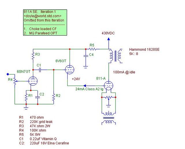
This is actually almost the exact operating point I use. Again, there's no feedback here to tame the damping and distortion problem, but you get an idea of how to setup the directly coupled cathode follower. The note on here about 24mA of grid current is definitely not what I've observed; it has been far less than that at idle.
This shows one way to deal with the feedback, which they've sent from the 811 plate to first stage cathode. You'll notice that instead of that series resistor going to the cathode follower, there's a solid state regulator. This is a nice idea.
You'll also need to DC heat the 811, which is 6.3V/4A, so big diodes with heatsinking is a good idea.
The cathode follower driver isn't all that hard to design, but getting the feedback dialed in took a lot of time. The plate impedance of the 811 is very, very high, so feedback of some form or another is 100% necessary. From my experiences, series feed transformers will not support the level of feedback required to make the 811 workable, so doing it all locally made the most sense. I would also suggest ignoring any schematic that says "SV-811-10" or "SV-811-3", as those are very different tubes. I would also ignore any designs that use an interstage transformer, as that makes implementing the feedback even more difficult.
Here is the architecture I use, though it's missing feedback:
An externally hosted image should be here but it was not working when we last tested it.
I would never build this. Damping factor will be way, way less than 1. I found that 6.2K resistor to also be problematic and changed it out for a cold cathode tube diode since the current through the cathode follower is highly variable. If you use a beefy double triode in the cathode follower position, sometimes you can use the second triode as a series regulator for the first, which is another way to deal with the problem.
This is actually almost the exact operating point I use. Again, there's no feedback here to tame the damping and distortion problem, but you get an idea of how to setup the directly coupled cathode follower. The note on here about 24mA of grid current is definitely not what I've observed; it has been far less than that at idle.
An externally hosted image should be here but it was not working when we last tested it.
This shows one way to deal with the feedback, which they've sent from the 811 plate to first stage cathode. You'll notice that instead of that series resistor going to the cathode follower, there's a solid state regulator. This is a nice idea.
You'll also need to DC heat the 811, which is 6.3V/4A, so big diodes with heatsinking is a good idea.
Last edited:
- Home
- Amplifiers
- Tubes / Valves
- 811 811A Amplifier