Hi,
everybody this is sekhar from INDIA (WB). This thread is dedicated to our great "Dr Bora" also known as "boraomega" in the forum .This thread is specifically dedicated to the great amps built by "Dr Bora".
It is a salute to his great contribution to the diyers . It is welcome note to all the people who has already built his amps or willing to built his amp .it will be a common platform for all the fans of Dr Bora & his amps.
I personally have made two of his amps
1. LEGEND STAGE MKII
2. STUDIO SE
Both of the amps r a master piece in it self .
Every body who has built Dr Bora's amps r requested to post their reviews and pictures .
their r many amps in this this forum that r liked and built by many diyers .Dr bora's amps does nt seem to be one of them as they r nt brought in light to the diyers . I will try my best to provide all the details of the amps built by dr bora of course with his due permission.
for a start I will provide the list of amps by dr bora.
1. CALOR- gold(CLASS A 40W)
2. Standard (50-60W RMS/8 ohm)
3. Lambda (100W RMS/8 ohm)
4. Legend(125W/8 ohm)
a.LEGEND-Stage Master(250W RMS/8 ohm )
b.LEGEND-Stage Master MK2(500W RMS/8 ohm)
c.LEGEND-QUASOR(1000W RMS/4 ohm)
5.Modus (aka Techno)
6.DOGC-MK3
7.Studio
8.STUDIO SE(80E RMS/8 ohm)
9.Epsilon(100-120W RMS/8 ohm)
10.Sigma
11.SubZero
12.CroSer( 100W RMS/8 ohm)
13.T-Reference
14.Goliath
15.Universal
16.Blaster
ALL OF THEM R VERY GOOD AMPS NO BODY HAS PUT SO MUCH EFFORT FOR DIYERS . HATS OF TO U DR BORA .
WILL PROVIDE MORE DETAIL LATER .....
DR BORA'S WEBSITE :- bas.elitesecurity.org
REGARDS
SEKHAR
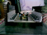
SOME OF DR BORA'S AMPS BUILT BY ME :-
everybody this is sekhar from INDIA (WB). This thread is dedicated to our great "Dr Bora" also known as "boraomega" in the forum .This thread is specifically dedicated to the great amps built by "Dr Bora".
It is a salute to his great contribution to the diyers . It is welcome note to all the people who has already built his amps or willing to built his amp .it will be a common platform for all the fans of Dr Bora & his amps.
I personally have made two of his amps
1. LEGEND STAGE MKII
2. STUDIO SE
Both of the amps r a master piece in it self .
Every body who has built Dr Bora's amps r requested to post their reviews and pictures .
their r many amps in this this forum that r liked and built by many diyers .Dr bora's amps does nt seem to be one of them as they r nt brought in light to the diyers . I will try my best to provide all the details of the amps built by dr bora of course with his due permission.
for a start I will provide the list of amps by dr bora.
1. CALOR- gold(CLASS A 40W)
2. Standard (50-60W RMS/8 ohm)
3. Lambda (100W RMS/8 ohm)
4. Legend(125W/8 ohm)
a.LEGEND-Stage Master(250W RMS/8 ohm )
b.LEGEND-Stage Master MK2(500W RMS/8 ohm)
c.LEGEND-QUASOR(1000W RMS/4 ohm)
5.Modus (aka Techno)
6.DOGC-MK3
7.Studio
8.STUDIO SE(80E RMS/8 ohm)
9.Epsilon(100-120W RMS/8 ohm)
10.Sigma
11.SubZero
12.CroSer( 100W RMS/8 ohm)
13.T-Reference
14.Goliath
15.Universal
16.Blaster
ALL OF THEM R VERY GOOD AMPS NO BODY HAS PUT SO MUCH EFFORT FOR DIYERS . HATS OF TO U DR BORA .
WILL PROVIDE MORE DETAIL LATER .....
DR BORA'S WEBSITE :- bas.elitesecurity.org
REGARDS
SEKHAR
SOME OF DR BORA'S AMPS BUILT BY ME :-
Attachments


Last edited:

Dr. Bora is not a selfpromoting man, therefore everyone are not familiar with his designs. He is truly a wonderfull person and perhaps it's our duty (us who have built any of Dr.Bora's projects) to get to world introduced to his designs. These are some of mine:
DoGC mk3
Studio
Tehno aka Modus - a good friend of mine refuses to give it back to me 🙂
Clepsidra preamp
Flat BTpreamp
DoGC mk3
Studio
Tehno aka Modus - a good friend of mine refuses to give it back to me 🙂
Clepsidra preamp
Flat BTpreamp
Attachments


I have to mention the the list of amplifiers provided ba sekhar is not even close to a full list of Dr. Bora's amplifiers. There is a number of hiend amps non listed in the website, but you have to contact Dr. Bora personally to get the stuff. I'm glad to say that Dr.Bora provided the material for Talisman Audio Grade ampllifier and i'm working on it.
Attachments

dear dr bora
greetings can you tell me which is a better choice tecton 1000 watts rms
or quasar 1000 watts in operation and sound quality
thanking you
andrew lebon
greetings can you tell me which is a better choice tecton 1000 watts rms
or quasar 1000 watts in operation and sound quality
thanking you
andrew lebon


Bora is the best designer we have in our forum..he deserves to celebrate his name
I do agree and i am here to say i am honored and proud to have his attention, respect and friendship.
regards,
Carlos
I do agree and i am here to say i am honored and proud to have his attention, respect and friendship.
regards,
Carlos
Thanks to all of you people! I am truly flattered and honored with this thread and all your posts. As Zikinho already mentioned, I am not of a “self-promoting” designers and I am rarely willing to give any kind of ranking of my designs. Other people should write about that, not me. Those designs already published on my site are FREE for personal use but that is just a part of my designs…
@ andrewlebon
I will suggest Legend Quazor (not Quasar !) as better option Andrew.
Special greetings and friendly hug for Carlos! First of all that man posses a glorious personality and is very experienced designer and builder, so praise from him is carrying a specific weight and I respect that!
@ andrewlebon
I will suggest Legend Quazor (not Quasar !) as better option Andrew.
Special greetings and friendly hug for Carlos! First of all that man posses a glorious personality and is very experienced designer and builder, so praise from him is carrying a specific weight and I respect that!
A good friend of mine refuses to return Tehno i've made recently and leaves me with no other choice but to assemble another one for myself. I started assembling Modus M using only one pair of output transistors. Thus, the pcb is smaller, good job by dr. Bora again.
Attachments

Last edited:
whr r other people ???????????????/............. many have built dr bora's design..... victor ur input is highly recommended..
regards
sekhar
regards
sekhar
@ andrewlebon
I will suggest Legend Quazor (not Quasar !) as better option Andrew.
that amp looks like a monster, and tempting
to use seperate supply(double), is it possible to remove diodes in supply rails between frontend and output stage
I can manage 55Vdc for output stage, and 60Vdc for frontend
and maybe just use 2x 3+3 IRFP240, instead of 2x 4+4
Of course "tinitus" you can omit those diodes and supply pre-stages from separate (preferably well stabilized) PSU and provide second separate high power DC source for output stage. Your voltages should be OK but you have to be aware of significantly reduced output power on 8ohms loads. On the other hand, number of output devices and those planed voltages will give you freedom to connect loads of much lower impedance - even 2ohms should still be safe. With such a low supply, requirements for some components will be much relaxed and many replacements will work satisfactory.
whr r other people ???????????????/............. many have built dr bora's design..... victor ur input is highly recommended..
regards
sekhar
Hi sekhar! What's up?!
Annual vacations are in progress, and because that there are only few people on the forums. Do you have a higher quality photo of studio-SE amplifier? Have you tested this amplifier? What transistors did you use?
Sekhar,
U is spelled "you"
R is spelled "are"
Please don't contribute to the destruction of my language. Thanks.
..Todd
U is spelled "you"
R is spelled "are"
Please don't contribute to the destruction of my language. Thanks.
..Todd
Of course "tinitus" you can omit those diodes and supply pre-stages from separate (preferably well stabilized) PSU
you have to be aware of significantly reduced output power on 8ohms loads. On the other hand, number of output devices and those planed voltages will give you freedom to connect loads of much lower impedance
With such a low supply, requirements for some components will be much relaxed and many replacements will work satisfactory.
that is great, thanks Bora

seems I may be facing a first time making my own boards, and hardwired outputs 🙄
You have my PCB for QUAZOR available on my site. Why would you develop your own... except if you strictly want that way? I would like to discourage you to hard wire output devices (if that is what you meant) because those are MOSFET-s…parasitics might spoil your adventure!
parasitics might spoil your adventure!
parasitics, thats to do with delay times
 due to distances, right 😕
I was thinking of roughly something like below, showing one mono amp
I suppose not very far from your board design
thanks fore the warning, something to think about

Attachments

hey, I see now that your actual board layout is different from what you show in the first seen picture, and much nicer looking, yeah
hmm, my heatsinks are still 400(L)x300(W)x40, of which I have two
Instead of cutting them into 4, I could use them as is, and your Legend Quasor boards would fit nicely
But I also like the idea of placing supply caps along the output dvices, and closer
decitions decitions 😕
but those boards looks good
Attachments
We are lucky to have people alike Borivoje Jagodic in our forum
not only happy but deeply honored is what i fell.
I use to say, to people in my place, that i am his friend, that he send me messages from time to time...that he even answer some of my messages.
hehehehe... This promotes me a lot...you do not imagine the respect they look at me.
The man is an Engineer, a skilled one, not a young engineer, a senior one!... with expertise and passion for audio, the man is a College teacher... anything can be better than that!
Lucky... very lucky we are.
regards,
Carlos
Last edited:
every mosfet (240) is fed or sunk via 0r22 source resistor from the +ve or -ve supply rails.But I also like the idea of placing supply caps along the output dvices, and closer
decitions decitions 😕
Why have split supply rails fed from both ends of the PCB? The resistance of the traces should be small in comparison to the 0r22
If the right hand end +ve & -ve are deleted, but you keep the output trace spkr tab at the right hand end, you will ifnd that the total trace resistance from +ve to output and from -ve to output is near identical for all mosfets. It's the same as a water radiator connected "tboe" (Top and bottom at Opposite Ends).
Last edited:
- Home
- Amplifiers
- Solid State
- "a thread dedicated to our great dr bora"