For some reason both channels of my amplifier thermal protection LEDs are on and the amp does not activate. This happens as soon as I plug in the unit and the power switch in OFF position. When I power on the amp, it does work, but no sound and the transistors are not getting warm at all (both channels). Any help would be appreciated.
That suggests somethings up with the protection circuit, or perhaps a power rail that supplies the protection circuit. From reading the manual those LEDs should only respond to temperature so it must be the protection circuit itself that's failing somehow.
I call that not working (!)When I power on the amp, it does work, but no sound
Thanks Mark. Yep, I agree, that the unit is not working. I just wanted to include as much information as possible and what I meant was that when I power on the unit, I can hear the Main Power transformer energize.
to add more information, I just checked all the voltages and it seems like the power supply card and circuitry is working fine. When I powerup the unit, the necessary voltages (correct) going to both side Amplifier and input boards are there. It seems like the problem is on (both) amplifier boards and for some reason the system protection is always activated.
Have you checked the thermal resistors attached to the heatsinks? Might be shorted or out of spec which is “tripping” the protection circuit. Compare readings from both channels and see if one is quite different resistance when cold.
Good point, do you know if the normal position of the T40 Thermal switch should be open or close? Mine are closed (shorted) in normal condition (both channels!). The schematic shows it being open.
If that’s true, then you could disconnect and see if it works? At your own risk, and for a short period only as a test.
I just disconnected one of the channel's Thermal Breaker, and same issue. Both channel thermal LED's stay on and none of the channels work.
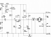
Time to take some measurements of that 555 chip and see what’s going on, then trace back to the component(s) causing the issue
That could be the case since I replace the 555s on both channels but used SE555 instead of LM555. I didn't think it would make a difference, but it is a possibility that it does. Thoughts?
I'm also trying to figure out if the 85deg thermal breaker is supposed to be open or closed under normal conditions.
LM555 datasheet says it’s a direct replacement for SE555, so that shouldn’t be the issue.
Looked at a few datasheet for thermal breakers and looks like they are closed and the “heating” causes separation and breaks. So you saying yours are closed/shorted when cold appears to be correct.
Have you checked the resistors and diodes/zeners in that circuit? Maybe one of these are out of spec or burned.
Thanks for the info regarding 555 and the thermal breakers. My next step is to replace the Zeners.
If you take some voltages from the 555, it should give you an idea of where to start, rather than just replacing parts.
Edit: have you tested diodes/zeners with DMM? That’s the first step to see if they are shorted. Then if you can test while powered you can get voltages on either side and tell you if it’s working properly.
Edit: have you tested diodes/zeners with DMM? That’s the first step to see if they are shorted. Then if you can test while powered you can get voltages on either side and tell you if it’s working properly.
good idea. For some reason the voltages from the 555 are showing higher than listed on the schematic. I'll check the diodes before replacing.
Sorry I can't help. 5802 was redesigned by the manufacturer that Adcom chose, and was very different from the 5800.
- Home
- Amplifiers
- Solid State
- ADCOM GFA-5802 Thermal Protection