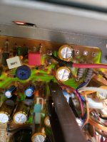
I am thinking of adding preouts to my Sanyo Plus 55 receiver. I used to be a licensed repair tech, so I can read a schematic and build from one.
I am not an engineer and would like someone to look at this.
I identified, on the schematic, what I believe are the outputs on the pre section and the inputs on the amp section. Circled in red.
I think this is the input to the amp section:

I think this is the output from the preamp section:

I am not an engineer and would like someone to look at this.
I identified, on the schematic, what I believe are the outputs on the pre section and the inputs on the amp section. Circled in red.
I think this is the input to the amp section:
I think this is the output from the preamp section:
Use the points labeled A and B for the left and right line outputs, on the power amplifier schematic
on page 36 of the service manual. The ground for each is also located nearby, run a twisted pair
of wires to each RCA line output jack.
Thanks, that is exactly what I thought.
These line outputs would be controlled by the receiver's volume control (and all the other controls),
is that what you want? If not, the outputs would have to be taken from either the existing "tape output"
jacks (which is easy), or else from a point in the circuit just before the balance and volume controls.
is that what you want? If not, the outputs would have to be taken from either the existing "tape output"
jacks (which is easy), or else from a point in the circuit just before the balance and volume controls.
Last edited:
These line outputs would be controlled by the receiver's volume control (and all the other controls),
is that what you want? If not, the outputs would have to be taken from either the existing "tape output"
jacks (which is easy), or else from a point in the circuit just before the balance and volume controls.
Yes, I plan to use the Sanyo as a preamp to a power amp. The tape output is just a line out with no control.
Ok, then the points A and B are what you want. Bear in mind that the signal will still be driving the
internal power amplifier unless (for example) the input coupling capacitors C701/C801 are removed.
Yep, my plan was to lift the input legs of C701/801, run wire from where the leg was to RCA jacks, may use the TAPE-2 jacks, and installing a switch to connect it back to the amp is so desired.
Ok, then the points A and B are what you want. Bear in mind that the signal will still be driving the
internal power amplifier unless (for example) the input coupling capacitors C701/C801 are removed.
I just had a thought, any reason that I couldn't just tap into the pre amp signal and also leave it connected to the Sanyo internal amp? It would be a simpler set up.
Then the internal amplifier would have output signals, sometimes a lot of it.
If you won't use the internal amp, best to disconnect its inputs.
Some integrated amps have both pre-out and amp-in jacks, with jumper cables (or a switch)
on the back.
I guess I need to add a switch then, thanks.
I finally got around to doing this and have a question.
I am using both sets of tape2 RCA jacks and will run to one set from the preamp and to the amp from the other set and use short RCA cables for jumpers if I want to use the Sanyo amp.
The preamp actually has wires going to the amp board making it easy.

The RCA jacks are pcb mounted and share a common ground which goes to chassis through a 0.01uF capacitor. The ground connection from the preamp to the amp board is also connected to chassis.
I was planning on leaving the ground connections as is and only cutting the signal wires at the amp connection, run them to the RCA jacks, then from the other RCA jacks back to the amp board. So I can use a jumper RCA cable when I want to use the Sanyo amp. I will cut the traces on the pcb where the signals go the RCA jacks.
So should do the grounding differently or is my plan OK?
I am using both sets of tape2 RCA jacks and will run to one set from the preamp and to the amp from the other set and use short RCA cables for jumpers if I want to use the Sanyo amp.
The preamp actually has wires going to the amp board making it easy.
The RCA jacks are pcb mounted and share a common ground which goes to chassis through a 0.01uF capacitor. The ground connection from the preamp to the amp board is also connected to chassis.
I was planning on leaving the ground connections as is and only cutting the signal wires at the amp connection, run them to the RCA jacks, then from the other RCA jacks back to the amp board. So I can use a jumper RCA cable when I want to use the Sanyo amp. I will cut the traces on the pcb where the signals go the RCA jacks.
So should do the grounding differently or is my plan OK?
Attachments
- Home
- Amplifiers
- Solid State
- adding preamp outputs to Sanyo Plus 55
