Hi!
I would appreciate any help checking my design/recommendations for alternate designs if these are just unworkable.
https://www.parts-express.com/30-Wa...ackage-with-2-1-2-Full-Range-Drivers-300-7304
Edit:
BLUF: Trying to get the best use of the PC68-4 driver. I wanted to make a speaker, and needed Christmas gifts for two nieces and nephew, so it needed to be inexpensive, include the amp and bluetooth. Initially wanted three different speakers, now not so sure (but I want to try either the Cornu or an equivalent flat wall mount speaker). I don't think these amps have integral DSP to help (apparently some Dayton amps do?).
Potential bonus: if I get a decent result, maybe it helps someone else out who purchased the kit, then went looking for plans.
Plan to separate the amps and make passive speakers so they can upgrade if they catch the bug.
I am thinking:
Vb (cu.ft) = 0.12 cu.ft / 3.4 l
Fb(Hz) = 71.9
F3(Hz) = 62.4
Port Dia = 15 mm
Port Len = 21 mm
I have attached the pictures from SpeakerBoxLite. They seem to match what I could squint sideways and see in the other programs (WinISD and Hornresp), but I don't really understand them. SpeakerBoxLite seems to automagically place and space the speaker and port, I don't know how to figure out speaker placement or spacing in the others.
If this looks OK, should the speaker go on the large side, or the narrow side? I thought the "Pico Neo" design had the speaker & port on the narrow side, but then I read something about having the speaker baffle (I take this to mean the side surrounding the speaker) to be at least the speaker diameter from the box edge to the speaker/cone edge, which gives something approaching the wide one.
And the calculated port seems tiny at 15mm, and the port velocity is off the chart. But when making that something like 25mm/1" it squiggles up the SPL graph. Although at 15mm, the length seems to essentially be the depth of the baffle at that size. Should I just drill a hole there, then see if it makes noise - thinking that I can always make a bigger hold and put a tube in there?
Thanks for any help,
Darrell
I would appreciate any help checking my design/recommendations for alternate designs if these are just unworkable.
https://www.parts-express.com/30-Wa...ackage-with-2-1-2-Full-Range-Drivers-300-7304
Edit:
BLUF: Trying to get the best use of the PC68-4 driver. I wanted to make a speaker, and needed Christmas gifts for two nieces and nephew, so it needed to be inexpensive, include the amp and bluetooth. Initially wanted three different speakers, now not so sure (but I want to try either the Cornu or an equivalent flat wall mount speaker). I don't think these amps have integral DSP to help (apparently some Dayton amps do?).
Potential bonus: if I get a decent result, maybe it helps someone else out who purchased the kit, then went looking for plans.
Plan to separate the amps and make passive speakers so they can upgrade if they catch the bug.
I am thinking:
- Best (flattest/smoothest?) sound without trying to get too deep, likely standard Ported Box?
- (Tentative) Prioritize lower extension. Maybe some type transmission line/horn (the terms here are confusing). Or a metronome, mini voigt tubes or voigt pipes (I think the mini-sawtooth ones look cool).
- (Tentative) Just for fun I think I will at least try some variant of the Cornucopya Foam Core, or other flat-ish mount on the wall design. That might even translate into another project for my living room TV (yes I could buy a soundbar I guess).
I am (planning to) build three speakers for my two nieces and nephew for Christmas. For [negotiation reasons], I already have and will use the Parts Express Part #300-7304 "30 Watt Powered Bluetooth Speaker Package with 2-1/2" Full-Range Drivers". [We] did not really reason myself into that driver selection, so reason won't help me out of it, it's fairly fixed. I am only trying to beat a couple cheap LCD TV speakers. If it's horrible, its the thought that counts anyway, right?
I have WinISD, Hornresp, and Leonard Audio TL downloaded and installed, and have been using the SpeakerBoxLite website.
I do not have any idea what I am doing, but have been playing the "monkey around until the graphs look like ones folks say are 'good'" game for a bit now.
I do not have a microphone to test with (maybe I will get one for my birthday).
My plan:
Build three different speakers for three different ~older teenagers. A secondary aspect is I plan to put the amp board in a different enclosure and build passive speakers. The thinking is if the bug hits them, they can upgrade as they wish later.- One listens to new-ish popular music, Chromecast to a small LCD TV, and talks of a subwoofer (yes I understand the 2.5" driver). She is also design focused.
- One listens to classic rock, somehow gets music out of her small LCD TV, and has a vinyl record player (not a good one, but still). She does not talk of a subwoofer (she laughs at her mom who consistently hears "sub" from the other one and thinks "Subway Sandwiches").
- The nephew listens to headphones in his room with his video games, no idea the genre.
My Experience:
None.I have WinISD, Hornresp, and Leonard Audio TL downloaded and installed, and have been using the SpeakerBoxLite website.
I do not have any idea what I am doing, but have been playing the "monkey around until the graphs look like ones folks say are 'good'" game for a bit now.
I do not have a microphone to test with (maybe I will get one for my birthday).
I am thinking:
- Part One: Standard Ported Box.
- Part Two: (Tentative) Voigt Pipe (the mini voigt tubes on Reddit looked cool to me) or some type transmission line/horn (the terms here are confusing). Not sure I like the open top in the BiB design. I cannot count on placement for corner/ceiling loading, and space is somewhat of a concern.
- Part Three: (Tentative) I think I will at least try some variant of the Cornucopya Foam Core. Wall mounting might be a good option (remember, two are coming from TV speakers and the [N]AF is strong in one). I will likely spend at least some time trying to get a method to calculate the paths for that (not to chase audible last 5%, it's just a puzzle that might make me happy). Heck if it works out well, I might try a better driver version for my living room (I have a long term plan, but need them out of reach for the moment until my two little destruction machines settle down a bit).
Part One: Standard ported box
Ql (Box losses) = 7Vb (cu.ft) = 0.12 cu.ft / 3.4 l
Fb(Hz) = 71.9
F3(Hz) = 62.4
Port Dia = 15 mm
Port Len = 21 mm
I have attached the pictures from SpeakerBoxLite. They seem to match what I could squint sideways and see in the other programs (WinISD and Hornresp), but I don't really understand them. SpeakerBoxLite seems to automagically place and space the speaker and port, I don't know how to figure out speaker placement or spacing in the others.
If this looks OK, should the speaker go on the large side, or the narrow side? I thought the "Pico Neo" design had the speaker & port on the narrow side, but then I read something about having the speaker baffle (I take this to mean the side surrounding the speaker) to be at least the speaker diameter from the box edge to the speaker/cone edge, which gives something approaching the wide one.
And the calculated port seems tiny at 15mm, and the port velocity is off the chart. But when making that something like 25mm/1" it squiggles up the SPL graph. Although at 15mm, the length seems to essentially be the depth of the baffle at that size. Should I just drill a hole there, then see if it makes noise - thinking that I can always make a bigger hold and put a tube in there?
Thanks for any help,
Darrell
Attachments


Last edited:
Hmm, FWIW, using these popular formulas for a T/S max flat alignment I get 3.379 L/74.37 Hz Fb, so you're fine as is.
Margolis-Small's HP 67/97 & 41C calculator program if wanting all the math for vented, sealed: http://www.aes.org/e-lib/browse.cfm?elib=3902
net volume (Vb) (L) = 20*Vas*Qts'^3.3
box tuning (Fb) (Hz) = 0.42*Fs*Qts'^-0.96
Re differing listening preferences, maybe excepting headphones (no experience), the ~117 Hz Fs makes it mostly a moot point beyond using DSP to shape the response to personal 'taste' due to being limited to FM radio BW performance on the low end.
Only the 'rocker' for sure needs a sub to get a live event's boom/punch in the upper bass and depending on which 'new-ish popular music' the other listens to most.
Re box design it's a basic acoustically benign room ratio with a traditional/familiar baffle layout, so internally it's presumed to have a ~uniform particle density, ergo with minimal internal damping; the driver, vent can be placed anywhere it pleases you/them, though mounting them both at the bottom gets a bit of boundary gain boost down low when setting on one.
OK. Thanks! I copy:
Not a lot can be done with the driver selection anyway. So make the box 3.379 l (206.2 cu.in) and don't worry too much about dimensions or where to place the speaker.
I didn't really understand the part about mounting them on the bottom. Presuming that is low on whatever face, not down-firing like a sub, is that meant to be reinforced by the shelf they are sitting on? Should I make them like a soundbar? I think there was another project with 3" speakers in three connected chambers, the middle housing the amp and power brick.
I get the driver isn't the greatest, but I know I would have started here, then escalated through C-Notes, C-Sharps, and probably been trying to build 3 Speedsters or something (like $1,500 total or 100x my gift budget).
v/r,
Darrell
I made some adjustments and made two prototypes from 1/2" foamcore board (seems to be 11-12mm). Port rationale: easier to go bigger later. I made the ports ~15mm with the ~11mm depth as the modeling seemed to say that was the ratio if I didn't use a tube (just the depth). The speaker has relief around the back of the mounting hole, but I used bolts without cutting them to size, so the bolt, nut, and a dollop of hot glue stick out in the way.
I just realized that I asked for help, then got lost in playing with the software so I didn't build a variant at 3.379 L/74.37 Hz, sorry.
I meant to have a tall one with ~12L / 68Hz to see what that sounded like and a smaller one with 3.3L/72Hz that seemed the flattest (green calculated line).
I think what I ended up with were:
Large (blue calculation): ~12.0-12.1L ... but 14mm port ~11-12mm so guessing at tune ~45 Hz?
Small (red calculation): ~2.7-2.8L ... but 15mm port ~11-12mm so guessing at tune ~93 Hz?
The tall one had a bump in the low frequencies, the smaller one I aimed at getting rid of the bump, but apparently I got lost and didn't (or more likely the difference between WinISD and SpeakerboxLite drove some of that).
A test play where there is no stuffing (forgot to even get pillow stuffing), and the back is held on by clamps (I think the tall one is sealed, the small one leaks a little).
My wife initially preferred the tall one, saying it had clearer highs - while sitting off-center (not quite patiently) to the left and well below the tweeter.
When asked to stand more centered about 8 feet away, she then preferred the small speaker, but could not articulate why.
Is playing with larger ports and/or stuffing worth the time? Or should I just go back and calculate the 3.3L box and play with that one?
Any other thoughts?
If I messed the ratio up and the tall one would be better a little taller, I can go to ~76mm for a foamcore test (higher in wood).
Also, I was going to adjust the front post to try and simplify it to the below, but I can't edit.
BLUF: Trying to get the best use of the PC68-4 driver. I wanted to make a speaker, and needed Christmas gifts for two nieces and nephew, so it needed to be inexpensive, include the amp and bluetooth. Initially wanted three different speakers, now not so sure (but I want to try either the Cornu or an equivalent flat wall mount speaker). I don't think these amps have integral DSP to help (apparently some Dayton amps do?).
Potential bonus: if I get a decent result, maybe it helps someone else out who purchased the kit, then went looking for plans.
Plan to separate the amps and make passive speakers so they can upgrade if they catch the bug.
I am thinking:
- Best (flattest/smoothest?) sound without trying to get too deep, likely standard Ported Box?
- (Tentative) Prioritize lower extension. Maybe some type transmission line/horn (the terms here are confusing). Or a metronome, mini voigt tubes or voigt pipes (I think the mini-sawtooth ones look cool).
- (Tentative) Just for fun I think I will at least try some variant of the Cornucopya Foam Core, or other flat-ish mount on the wall design. That might even translate into another project for my living room TV (yes I could buy a soundbar I guess).
Attachments
-
 PC68-4_Tall_A_3D.png48.2 KB · Views: 147
 -
 PC68-4_Tall_A_Front.png6.1 KB · Views: 112
 -
 PC68-4_Tall_A_side.png3.1 KB · Views: 110
 -
 PC68-4_box_C_3D.png59.6 KB · Views: 120
 -
 PC68-4_box_C_side.png2.9 KB · Views: 105
 -
 PC68-4_box_C_front.png7.7 KB · Views: 115
 -
 prototypes_1.png29.3 KB · Views: 148
 -
 First_Test_small.jpg672.5 KB · Views: 162
You're welcome!OK. Thanks
I didn't really understand the part about mounting them on the bottom. Presuming that is low on whatever face, not down-firing like a sub, is that meant to be reinforced by the shelf they are sitting on? Should I make them like a soundbar?
I get the driver isn't the greatest, but I know I would have started here
Correct.
Only if it is required for the needs of the app.
Understood, I started by mounting a car's in-dash mono oval driver in an empty Kleenex tissue box because of its oval opening, so you're way ahead of me. 😉

Scaling vents more to come later after the NASCAR race. 😉Port rationale: easier to go bigger later. I made the ports ~15mm with the ~11mm depth as the modeling seemed to say that was the ratio if I didn't use a tube (just the depth).
Thanks again! I was able to do some more tinkering.
The story leads to a question:
With the wife as the "ear", I tried taking the large box and putting a full diagonal piece inside (halving the volume by making a triangle with the small end at the bottom port), she wasn't going to hear the difference between those configurations in that speaker (given the time between listens), but I was comparing to the other one and she still preferred the smaller speaker.
I tried a cutting the top off the diagonal, something like a folded horn (again with small end at port) (not modeled or anything, but I did try to get it roughly proportional to drawings I have seen). She preferred the smaller speaker.
I cut the tall speaker down to the ~3.3L as suggested above, with the 15mm-D 12mm-L. For cable length reasons I laid both down sideways. She stated no preference. ...
So I glued that up and re-routed the cable to make them upright again, she was somewhat ambivalent. I thought, maybe that was the [boundary gain], so I put them on coffee cans (up off the work-bench). She again preferred the smaller speaker.
I then looked into the ports. If I get your reference, that is designed to maintain the same tuning, where I was trying to adjust the tuning to get a flatter response curve, as low as I could get it.
So I adjusted the port on the large box to take it to the 3.3L/~79Hz. She preferred the smaller speaker (and side effect of using foam is likely now getting a little annoyed I keep calling her into the garage as it doesn't take long to make these modifications).
Then I adjusted the port on the smaller box to take it to 2.7L/~80Hz. She then had no preference.
Question: So is this simply more that my wife prefers the bump in the bass? Or that louder bass beats flatter response because louder is better (and we are dealing with a 2.5" driver)? Was I on the right track about the sideways / upright on bench / upright off bench on coffee cans - was the [boundary gain] increasing the lower end? If so, then maybe it's not a speaker design change, but instructions to the young folks that they should experiment with orientation and placement?
So now I am tempted to just build the smaller speaker at the original tuning. It drops off earlier, but boosts higher and earlier (much more area under the curve). Would that be rational? It seems kind-of like the "loudness button" and maybe not as distorting since the speaker is so small to begin with (is that in the same ball-park with what Audyssey does with it's low volume correction)?
I might try to figure a way to make it a choice using a plug or something so with the plug in you get the 93Hz bass boost tuning and with it out you get the 80Hz flatter tuning.
Anyway, thanks for the help!
Attachments

You're welcome!Thanks again!
The story leads to a question:
I then looked into the ports. If I get your reference, that is designed to maintain the same tuning, where I was trying to adjust the tuning to get a flatter response curve, as low as I could get it.
Question: So is this simply more that my wife prefers the bump in the bass?
So now I am tempted to just build the smaller speaker at the original tuning. It drops off earlier, but boosts higher and earlier (much more area under the curve). Would that be rational?
Correct, can't recall ever seeing one like you want other than in box design software.
In this case, yes; to wit, re the 'bump', she's most likely hearing the impact its 'ripple' is having on her > ~240 Hz BW.
Women's hearing is different from men's in that where a man hears bass 'fullness' at ~120 Hz, the females only hear it ~a full octave higher at ~240 Hz whereas the male hears it as 'boominess', so falls right in line with your empirical findings, i.e. she flat can't hear it, only feel it and your speakers aren't powerful enough to 'move' her like at a live event, hence her ambivalence. This is why prosound has historically had a flat ~80 - 300 Hz to provide satisfying 'fullness' for both sexes.
This is also why she is more attuned to a baby's crying, etc., since she lacks the bass's 'masking' effect on the ~4 - 10 kHz sibilance/definition BW that allows us to hear clearly over a wide range of vocal variables, background noise.
Reference: interactive musical, human hearing charts.
Correct, can't recall ever seeing one like you want other than in box design software.
Thanks, that helps a lot! (edit: actually referring to the non-quoted parts).
Although, other than the driver, in my ignorance, I thought I was trading extension for [something else] but not anything too far out of the norm. (and focusing on getting the little dip out more than knocking down the hump at the end)
Still reading and learning, apparently that trades away [something] that I can't see/intuit in the graphs yet (much less identify/distinguish by ear).
I'm a little dense on subtle hints, so if what I am trying to do is the equivalent to salting the field to have pre-salted pop-corn, and it's compromising both rather than trading between ... I could use a stronger suggestion (on anything but the driver, I'm stuck with that for this project).
If I need to go back to something without that bump at the end because it will sound better, I can still do so (I even built a little switch box to help A/B the speakers, although there is a definite click using two DPDT on-off-on switches).
I don't have to commit to construction of the wood versions just yet, so I was just going to keep the little one as [Minimum Viable Gift = the one my wife said was acceptable] and move on to the next variant. So I can get better, but I have a baseline that (I thought) was OK.
I started looking at some "labyrinth" style speakers that Scottmoose and planet10 had for a number of small drivers. I pulled the T/S parameters for the various designs to see if there might be some ball-park starting point. But while the PC68-4 falls inside the range for a number of T/S parameters, it's Vas is way off (half the smallest) of that collective group and the dimensions vs T/S parameters don't seem to align to a discernable pattern. So that's not looking like a fruitful path. (I have HornResp, WinISD, and the LA T-line programs to play with, but i don't have FaceBook, so I don't have the MathCad worksheets).
I will probably knock on a bit with the foam core stuff. I might try some type of "maze" if only to at least try to get something that could be wall mounted as a slightly thick painting.
-Darrell
Right, in audio we're always trading efficiency for bandwidth (BW), so acoustically can only get rid of the dip/bump by tuning higher to fill it in, then maybe need to critically damp the vent to get a flat response with good 'toe tapping' transient response.
Thanks! I didn't figure out the link until just now, so I probably won't get to build and try that out this weekend.Right, in audio we're always trading efficiency for bandwidth (BW), so acoustically can only get rid of the dip/bump by tuning higher to fill it in, then maybe need to critically damp the vent to get a flat response with good 'toe tapping' transient response.
I did work up another version. It beat the adjusted small box in the Wife test (I think she still preferred the one with the larger hump, I haven't made something to take the port out and put it back to a simple 15mm hole yet). The thing in the back is an 8" speaker from an old guitar amp that someone threw away. I hooked it up to give some perspective when switching between speakers.
What I think the new box comes out to is in the picture, with the two adjusted boxes. It doesn't quite flatten out the response (its still got inflection points), but it seems to have knocked down the hump. And it won.
It's a little off what I meant to do because (1) I forgot to double the height to account for the [vent shelf] so I cut things wrong and had to adapt things on the fly, and (2) I meant to have asymmetric ports (per planet10's comment for another driver that I thought was similar) - but when I stepped back, I realized 8x8x39mm ports are essentially circles and he was probably talking about cross-sectional height vs width, not a narrow & long cylinder vs a short & fat one.
And, for anyone who might have been interested, I did figure out a way to calculate a very close approximation of the Cornu spiral (spiro, clothoid, or Euler spiral, etc.), but then I saw comments that smooth radiused turns in folded transmission lines were "counter-productive" ... and since the primary use for that spiral is to generate smooth transitions in roads/rails (curvature changes linearly with length) ... that seemed like going double speed in the wrong direction. So although this is about smooth changes in acceleration in something forced into a curve, not expanding gases/waves, but if someone wants the equation for a horn or something, I have an Excel worksheet with a fast numerical approximation (from a research paper I forgot to bookmark). although since that was meant for a specific application, using it for this is still curve fitting like playing with the box in WinISD, not like plugging boundaries in and getting the exact solution.
-Darrell
Attachments


Holy Schnikes, it's been a month*! I really need to cut sling-load and get moving on the final builds.
I didn't get to build the Click-Tester yet (never found a time that I could get a good set of ears to help).
The day after the ton of "mudd", I built what I think is a mass loaded Voigt pipe (dimensions below). That one and the one with the four small vents seem to be the front runners.
Q: I put some stuffing (rolled up some 1" "Renewliner" which seems to be poly-wadding) in the box variants, basically filling most of the space. Given the time lag and lack of a microphone to measure, should I take that out and have the kids pull it apart to make it "fluffier"?
Q: On the ML-Voigt, I stuffed the top down to just past the driver, and believing best practice was rather dense stuffing at the top, it was to the point that I had to compress it to glue the back on. Initially, I also had another bunch at the bottom until just above the port. Given the question below, I pulled the lower stuffing out, again, without a microphone, it was way too long to try to compare with my ears. Should I try to pull that out?
Q: The ML-Voigt seems to sound close to the 4-port box in the lower frequencies, but it seems to be much louder in the mid and higher frequencies (noting that I am usually between them on the switch-box, I haven't been back at the 6 feet mark just listening). I initially thought it might be coming from the different heights of the driver (the square boxes are at my waist and the ML-Voigt is just above my ear). But others have mentioned it also, so I think some of it is true. While I plan to get some opinions on preference there (I don't expect the recipients will be bothered with the flatness of SPL charts as a goal), is that the effect of the narrow & tall baffle? Can you predict which would be closer to flat? If the preference is for less [treble], is that what a baffle step compensation circuit is for?
Q: Did I get close in how to design a ML-Voigt? If so, could this be folded down into something like scottmoose's labrynth series? I have tried to read up on the modified centerline and folding techniques, but it's not really coming clear to me.
Q: If the perceived treble boost is actually preferred (whatever my opinion of that), would that be enhanced or inhibited by folding and putting the driver at the top?
Edit - Oh, I got a DATV3 for my birthday, but I don't know how to use it, would getting that going help this near term? I have Linux loaded on an old Chromebook, but using the Windows software will likely require taking over the wife's computer for a bit inside. Does that make a lot of noise, that would get me kicked out.
*Edit 2 * - the graphs are from the LA Transmission Line program, not measurements and not the WinISD from before.
Thanks for any help!
The ML-Voigt was:
8 cm x 7 cm inside base = 56 cm^2
110.1 cm inside tall
~52 cm driver centerline below top
~101 cm port centerline below top
~3 cm port diameter = 7.069 cm^2
~6.3 cm port length
(noting that I doubt I got 1mm accuracy with foam and hot glue along the length of this thing, where the glue was setting before I got the whole side done, this one won't get hide glue if it gets built)
*(Deck stair tread was rotten, went to replace it, stringers were in bad shape. Back to the store to replace them and since the main deck boards will need it soon, might as well get them also. Start taking the stairs out, dogs have been digging under there and now there is a huge washed out cavern under the concrete slab. So that's a weekend. Next weekend, prep, renting a mixer, 4 solid hours of mixing a literal ton of "mudd" or fill-flow, clean-up, then it's another weekend waiting to cure, which was a trip to see the kids' OMA & OPA, then sudden travel for work, ...)
Attachments


Last edited:
@GM, sorry to bother, but I saw the below post about using the 8 ohm version of this driver in an Open Baffle. Is that something viable for a third design, assuming I just want three designs? I will build the small 4-port version, and unless I figure out how to fold and tune the ML-Voigt into a labyrinth or something, the other will probably be the previous ~2.7-2.8L /93 Hz 15mmO x 12mmL port.
... Simple enough, if 'super accurate' female voice is the primary goal, then a 2.5-3" frame driver with a ~3/4"[0.75"]/1.9 cm dia. voice coil [normally listed in the driver specs] with a ~170 Hz or less [Fs] in either a max flat [0.707 Qtc] sealed cab or for open/infinite baffle [OB/IB], a ~0.5-0.71 Qts and use a good quality potentiometer [pot] to dial in ['voice'] its most pleasing in room response.
Only looked at PE and while I prefer to go bigger, their 3" has a ~7/8"[0.875"]/2.22 cm dia. voice coil, but this 2.5" is [surprising] close enough spec wise and plenty cheap enough to recommend trying it on OB with maybe a bit of EQ at each end to flatten it overall, so using an inexpensive 25 ohm pot will suffice since ideally need to audition at < ~2m/6.5 ft.
Dayton Audio PC68-8 2-1/2" Full-Range Poly Cone Driver
https://www.parts-express.com/pedocs/specs/295-152--dayton-audio-pc68-8-specifications.pdf
Well, I have the (planned) wood for the speakers now.
In case these help, it was raining so I had time to play with the DATSV3 thing-y. As with a lot of tools I get for my birthday, not sure it helps me as I don't understand what to look for (or what looks different but is relatively unimportant), but it was interesting seeing the change if I held my finger over the ports.
I don't know if I should go back and re-run the simulations with this measured data, or just use it comparatively. I also compared 'calibrating' against the test leads and then with all connections to the speaker terminals. That compare is there as well visually (but I forgot which was which, so I won't put the numbers in the table).
If a smoother impedance trace is preferred, it seems I may not have done too bad with the ML-Voigt, now I wonder if I can fold it properly.
The 4-port picture is: base driver = red/blue, speaker = pink, 2-ports covered = yellow
The ML-Voigt is: base driver = red/blue, speaker = teal, port covered = green
The 1-Port picture is : base driver = red/blue, speaker = pink, port covered = yellow
And the parameters the system calculated in case they are useful.
Thanks for looking!
In case these help, it was raining so I had time to play with the DATSV3 thing-y. As with a lot of tools I get for my birthday, not sure it helps me as I don't understand what to look for (or what looks different but is relatively unimportant), but it was interesting seeing the change if I held my finger over the ports.
I don't know if I should go back and re-run the simulations with this measured data, or just use it comparatively. I also compared 'calibrating' against the test leads and then with all connections to the speaker terminals. That compare is there as well visually (but I forgot which was which, so I won't put the numbers in the table).
If a smoother impedance trace is preferred, it seems I may not have done too bad with the ML-Voigt, now I wonder if I can fold it properly.
The 4-port picture is: base driver = red/blue, speaker = pink, 2-ports covered = yellow
The ML-Voigt is: base driver = red/blue, speaker = teal, port covered = green
The 1-Port picture is : base driver = red/blue, speaker = pink, port covered = yellow
And the parameters the system calculated in case they are useful.
| Driver | 4-Port | 4-Port cover two | 4-Port cover all | ML-Voigt | ML-Voigt cover | 1-Port | 1-Port cover | |
| f(s)= | 107.3 | 132.1 | 123 | 118.3 | 122.3 | 117.9 | 124.6 | 111.7 |
| R(e)= | 3.72 | 3.69 | 3.70 | 3.72 | 3.87 | 3.89 | 3.65 | 3.64 |
| Z(max)= | 14.7 | 12.6 | 13.4 | 13.7 | 13.0 | 13.6 | 12.1 | 13.3 |
| Q(ms)= | 2.44 | 2.96 | 2.76 | 2.59 | 2.51 | 2.56 | 2.55 | 2.57 |
| Q(es)= | 0.83 | 1.22 | 1.05 | 0.97 | 1.06 | 1.02 | 1.11 | 0.97 |
| Q(ts)= | 0.62 | 0.86 | 0.76 | 0.70 | 0.75 | 0.73 | 0.77 | 0.70 |
| L(e)= | 0.083 | 0.086 | 0.087 | 0.087 | 0.092 | 0.092 | 0.082 | 0.081 |
| K(r)= | 0.099 | 0.077 | 0.089 | 0.069 | 0.121 | 0.109 | 0.100 | 0.093 |
| X(r)= | 0.385 | 0.408 | 0.395 | 0.419 | 0.371 | 0.380 | 0.382 | 0.389 |
| K(i)= | 0.00204 | 0.00223 | 0.00167 | 0.00260 | 0.00306 | 0.00313 | 0.00252 | 0.00225 |
| X(i)= | 0.712 | 0.704 | 0.730 | 0.689 | 0.679 | 0.676 | 0.693 | 0.703 |
Thanks for looking!
Attachments


I got tired of waiting for my better ears to get done stressing about Thanksgiving and now she's onto Christmas, so I went ahead and tried the "click-test".
I wasn't able to hear much of a difference, but I also had put stuffing in most of them. Not sure if I should take that out and just try to damp the port.
So, that'll wait until she's ready, but I am afraid I won't be able to explain what she's listening for. Probably doesn't matter, if she hears it we'll fix it, if not, probably won't bother them anyway.
Probably talking to myself now (ha!) but I raised two teenage step-daughters the first time around, so that's not an familiar feeling.
Short on time for now with way too many to respond to both online and private, but ideally for a typical square/rectangular box is to lightly line one wall, top, back down to ~one driver radius and then do the 'click' test. If you build the box such that the internal dims are a golden or acoustic room ratio, then just ~driver size pads.
Not a 'believer' of stuffing typical box alignments unless to the point of (dramatically) reducing any high QT alignments, but rather to initially 'hang'/suspend a 'blanket' between the driver, back wall or more as required.
That said, FWIW/YMMV, some folks that I've done MLTL cabs for (huge, up to 30+ ft^3) have even preferred no damping at all over my already minimalist standards relative to what most folks/sim-wares seem to prefer and from the get-go in my 'adventures' in audio all mine have been fine tuned by women beginning with my mom. If there's a truer statement than "if mom's not happy, nobody's happy", I've never seen/heard it. 😉
Last edited:
Awesome, and thanks for taking the time! I'll have to start committing things in wood now, so I hope it'll be pictures and not questions.
I'll take the stuffing out then, and look to the click test when she's ready. I think I liked the ML-Voigt better when I took out the lower stuffing anyway (It's still in the top, I didn't want to risk it being horrible without it because I don't have a good way to get it in after the fact).
-Darrell
If it's a 'pointy' top, then in general it does need a wad IME and being tapered it only needs some damping on one side wall with 'click' testing dealing with its pipe modes.
Hope everyone had a Merry Christmas (other holiday, or Bah! Humbug! as appropriate)!
And thanks for all the help!
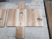
As promised, next post is one with pictures. Always late, I finished putting the amp boxes together and two of the sets of the speakers.
I won't bore folks with the wood shenanigans, suffice that I did not have the access to a suitable bandsaw for resawing that I anticipated, so I resorted to cedar stock, I am aware of the impact of wood movement, the miter vs butt joint was dictated, since the cedar stock had a rough side, I left it on the interior, figuring it couldn't hurt.
I used that DATS device to measure the impedances before they were spirited away, it's just not on this computer.
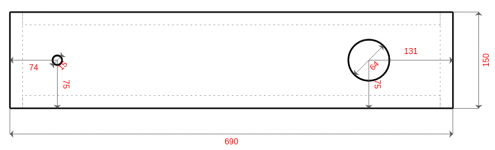
Strange to me, the 1-Port sounds a ton "deeper' than the 4-Port, although tuned to the same ~85Hz I expected a little bump due to the larger size, but the difference is startling using the simple (non-compensating) switch-box I built.
I am not sure if that is cabinet resonance, the stereotype "boomy bass", or what.
The wife said she preferred the 4-port for vocals, the "more bass-y" 1-Port for instrumentals, and the 4-Port might get annoying after a while (making me think I should have pulled out the BSC stuff again, but time was out).
Still working on the third set, which is planned for an oblong sphere-ish design using bowls from Target with some spacers and radial ports - taking the idea from a planet10 post (I don't have pictures of that one yet).
And thanks for all the help!
As promised, next post is one with pictures. Always late, I finished putting the amp boxes together and two of the sets of the speakers.
I won't bore folks with the wood shenanigans, suffice that I did not have the access to a suitable bandsaw for resawing that I anticipated, so I resorted to cedar stock, I am aware of the impact of wood movement, the miter vs butt joint was dictated, since the cedar stock had a rough side, I left it on the interior, figuring it couldn't hurt.
- I tried the critical-damping test, but my wife did not hear differences, so ports are clear (despite the stuffing in one of the pictures).
- With the 1-Port, I calculated and tried a Boundary Step Compensation (~3.7 Ω, .50 mH) using Basta! (physically I used a DPDT switch for a/b), wife said she only heard "it" when it came back and she preferred it without.
- Was running out of time when the 4-Port set was done, so I didn't try the BSC.
- Neither set had any stuffing - I just didn't have time to go find the right stuff (so only the golden ratio on the 4-port, a slightly different ratio set on the 1-Port - but in the set of ratios I found somewhere, and the rough interior).
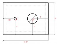
- I wanted square ports on the 4-Port, but it was too complicated for the time I had, both in terms of construction, and trying to figure out the calculations between round and square ports (and placement, with that chart you post, my German is negligible and my wife's is not technical).
I used that DATS device to measure the impedances before they were spirited away, it's just not on this computer.
Strange to me, the 1-Port sounds a ton "deeper' than the 4-Port, although tuned to the same ~85Hz I expected a little bump due to the larger size, but the difference is startling using the simple (non-compensating) switch-box I built.
I am not sure if that is cabinet resonance, the stereotype "boomy bass", or what.
The wife said she preferred the 4-port for vocals, the "more bass-y" 1-Port for instrumentals, and the 4-Port might get annoying after a while (making me think I should have pulled out the BSC stuff again, but time was out).
Still working on the third set, which is planned for an oblong sphere-ish design using bowls from Target with some spacers and radial ports - taking the idea from a planet10 post (I don't have pictures of that one yet).
Attachments
-
 1-port_Straight_layout_reverse.png625 KB · Views: 124
 -
 1-port_Straight_layout.png579.9 KB · Views: 107
 -
 1-Port_testing.png340.7 KB · Views: 181
 -
 1-port_Wavy_layout.png565 KB · Views: 109
 -
 1-port_Wavy_layout_reverse.png583 KB · Views: 114
 -
 Completed_1-Port_4-Port.png344.7 KB · Views: 115
 -
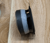 Driver_hot_glue.png868.2 KB · Views: 112
 -
 Driver_in_recess.png1.4 MB · Views: 170
 -
 Glue-up_4-Port.png409.5 KB · Views: 113
 -
 Glue-up_w_prototypes_amps.png394.5 KB · Views: 126
 -
 Oiled.png346.9 KB · Views: 132
- Home
- Loudspeakers
- Full Range
- Advice for Niece Niece Nephew (N3) Project - 3x PE 30W Speaker Packages Dayton Audio PC68-4