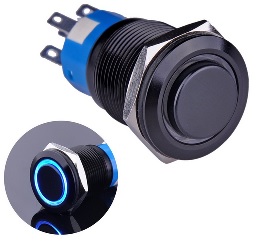
I am trying to figure out a simple and practical way to use one of those "vandal-proof" illuminating push-buttons to turn on/off an amplifier unit:

Besides it's main output, my power supply board has an auxiliary +21V rail that would work a treat to power up the button's LED once power is on. A latching SPST switch of that sort with contacts rated up to 250VAC/5A is relatively easy to source. However my power supply is specified to draw up to 75A inrush current. I don't want to use switches rated for 5A to turn it on/off directly. I am now looking at relay-based solutions with appropriate specs.
This is all an afterthought so I'm sort of short for chassis room. I'm keen to keep the extra circuitry as minimal as can be (e.g. avoid an extra dedicated power supply circuitry, transformer, etc). I came across illuminating piezo switches with an LED ring. If I'm not mistaken, piezo switches generate a voltage pulse between their poles when they are strained mechanically and don't need to be powered. Correct me if I'm wrong but I don't reckon I need debouncing circuitry for this particular use-case.
Within those parameters, wouldn't there be a minimal way to use a piezo push-button to trigger a relay contact without dedicated power supply circuitry?
If that is impossible, maybe a very small form factor PCB exists to solve this. I haven't found anything ideal yet but I am open to suggestions. I am already aware of the following solutions, all of which involve more circuitry than I seem to need (soft start, LED driver, etc.):
Attachments

All the piezo switches I am finding are momentary, so you at least need a flip-flop to go off and on.
Mechanical toggles may be easier to find. (And much cheaper?)
Mechanical toggles may be easier to find. (And much cheaper?)
I was hoping there would be some kind of latching relay with which that would work. I don't really see any other option than to have a dedicated PSU then.
Is anyone aware of a small form-factor switch driver board, with low EMI emissions? (Prefereably pre-built, and with onboard or very small transformer.)
Is anyone aware of a small form-factor switch driver board, with low EMI emissions? (Prefereably pre-built, and with onboard or very small transformer.)
Last edited:
Mechanical toggles may be easier to find. (And much cheaper?)
There are latching switches with this kind of illuminating LED ring, they are just not rated high enough fro the inrush drawn by my amp.
One option would be to have a transformer + graetz bridge + capacitor circuit always powered on (e.g. 5V), and a latching SPST illuminating switch closing/opening the contact around the relay coil? (edit: e.g. like that)
Attachments

Last edited:
> There are latching switches with this kind of illuminating LED ring, they are just not rated high enough fro the inrush
So use the latching switch to work a power relay. You can get line-voltage AC relays.
So use the latching switch to work a power relay. You can get line-voltage AC relays.
I should have enough room to fit a Lascar PSU 30205 and a Pololu Mini Pushbutton Power Switch driver (LV) conveniently and safely, which I think will do the trick with a momentary SPST illuminating switch.
Ratings are:
Looks good to me, am I missing anything? Should I check anything else?
Ratings are:
- Pololu switch driver:
- Recommended operating voltage: 2.2 V to 16 V
- Current consumption in on state: ~210 μA/V
- Current consumption in off state: ~0.01 μA
- Lascar PSU 30205:
- Input Voltage: 220 / 240 / 250 V a.c.
- Output Voltage: 5 V d.c.
- Output Current: 100 mA
Looks good to me, am I missing anything? Should I check anything else?
Last edited:
I think you are making it more complicated than it needs to be with your switch driver and PSU.
I suspect PRR was suggesting a relay with a 240 volt coil. Like this. RS Pro DPDT Non-Latching Relay Plug In, 240V ac Coil, 10 A General Purpose Relay | RS Components
... maybe I am missing something too, but isn't a 'soft start' of some kind what you really need? Something where the in rush is absorbed by a big resistor (as heat) then after the in rush the resistor is shorted by a relay contact. Don't Hypex do one for the power supply?
You can get line-voltage AC relays.
I suspect PRR was suggesting a relay with a 240 volt coil.
Ok I get it now, I was not aware that AC-controled relays existed.
I've had a good look around and I haven't found a traditional coil-based AC-controled relay specified for load currents any higher than 30A or 40A. However I also discovered SS relays, some of which can withstand much higher load currents. This one is specified for 75A, dimensions 57.2 x 44.5 x 23mm which I should manage to safely fit in my chassis.
questions:
- is there any reason why I shouldn't use a solid state relay?
- I don't understand what the spec "Switching Type: Random" means, can someone explain?
- Off State Leakage Current is 12 mA. Pololu switch driver's is ~0.01 μA. Is 12mA a lot for a home appliance?
- wiring is like so, right?
Attachments

Hi Pierrex3,
To answer the questions,
1 - No, but there are so many types and getting the 'right' one will prove more complicated than you imagine. A mechanical relay is a mechanical relay.
2 - Random means it can switch on at any point in the AC sine wave, from zero to peak voltage, randomly. Again complicated to say which is better for which power supply.
3 - Not really. But
4 - OK. But
But with all the schemes so far, you are still trying to switch a possible 70+ Amps. Ok fit a 75 Amp relay, but what is the current rating of your mains consumer unit fuse / trip / circuit breaker? Not 70 Amps... It will trip out.
You really do need to explore fitting a Soft Start module. Like Hypex Electronics B.V.
You will eventually have to, sorry.
Why not ask another question, ''how have others solved the 'Hypex xxxx' switch on inrush current situation?''
A bit more info here about Inrush and soft starts. Soft-Start Circuits
Last edited:
Thanks for your reply and further explanations Alan.
I'm not sure what's my mains breaker tripping threshold but, although you make a good point about soft starting, I may have misrepresented what I'm actually dealing with when I said "up to 75A inrush current".
To be exact, my PSU datasheet specfies:
Practically speaking, I have plugged my PSU loaded with 1 amplifier module into the mains a couple of times and the mains breaker never tripped. I'm happy for my mains to trip in the odd case when the PSU might actually draw 75A on startup, which seems rare, and to do without soft start circuitry. I guess one might say that a relay rated for 75A is be overkill?
Going back to wiring it all, should I include resistors anywhere?
For example, on my schematic, nothing seems to be limiting the current drawn by the following loop:
I'm not sure what's my mains breaker tripping threshold but, although you make a good point about soft starting, I may have misrepresented what I'm actually dealing with when I said "up to 75A inrush current".
To be exact, my PSU datasheet specfies:
Parameter: In-rush current
Conditions: 5Ω In-rush NTC, worst-case
Max: 75A
The closest mention to soft-starting I found in the official documents for that PSU is the fuse rating: "250Vac, slow blow 5A". I did enquire about soft-start requirement with their customer support and, perhaps confusingly, they replied that "A soft start is usually not required. Only when powering on multiple SMPS’s at the same time.".Conditions: 5Ω In-rush NTC, worst-case
Max: 75A
Practically speaking, I have plugged my PSU loaded with 1 amplifier module into the mains a couple of times and the mains breaker never tripped. I'm happy for my mains to trip in the odd case when the PSU might actually draw 75A on startup, which seems rare, and to do without soft start circuitry. I guess one might say that a relay rated for 75A is be overkill?
Going back to wiring it all, should I include resistors anywhere?
For example, on my schematic, nothing seems to be limiting the current drawn by the following loop:
live
-> pushbutton (contact rated 250Vac/3A for resistive load)
-> Relay control (current max. 10 mA)
-> neutral
Wouldn't that be a short circuit when the switch is closed? And similarly, how about the "auxiliary PSU <-> LED" loop?-> pushbutton (contact rated 250Vac/3A for resistive load)
-> Relay control (current max. 10 mA)
-> neutral
I did enquire about soft-start requirement with their customer support and, perhaps confusingly, they replied that "A soft start is usually not required. Only when powering on multiple SMPS’s at the same time.".
Practically speaking, I have plugged my PSU loaded with 1 amplifier module into the mains a couple of times and the mains breaker never tripped. I'm happy for my mains to trip in the odd case when the PSU might actually draw 75A on startup, which seems rare, and to do without soft start circuitry. I guess one might say that a relay rated for 75A is be overkill?
Going back to wiring it all, should I include resistors anywhere?
For example, on my schematic, nothing seems to be limiting the current drawn by the following loop:liveWouldn't that be a short circuit when the switch is closed? And similarly, how about the "auxiliary PSU <-> LED" loop?
-> pushbutton (contact rated 250Vac/3A for resistive load)
-> Relay control (current max. 10 mA)
-> neutral
As they say ''A soft start is usually not required'' and you have tried it already and the occasional 'trip' is no problem then why not just go for a mechanical relay (like the link I posted before) and see how it goes?
I would not recommend the solid state relay option, you have no idea how it will react with the power supply you have.
Follow your circuit, but replace the SSR with a mechanical one. No leakage, no shorts, simple.
The relay will protect the push button switch, you can parallel both contacts in the relay so it has a 20 Amp rating, if you use a plug in version you can easily change it if it fails.
A resistor will only work if you can delay the relay closing, so not needed now.
Re the breaker tripping in simple terms, as you know the AC voltage is a sine wave, so the current also has to be a sine wave. Depending on the exact moment you switch on (you have no way of knowing) you can hit a peak current part of the wave and the PSU capacitors are empty so also ask for a lot of current at that same time... your mains will try to deliver it but exceed the trip breaker rating - pop. You might never hit that spot or you might hit it 2 or three time in a row, all chance.
Alan
Attachments

...I haven't found a traditional coil-based AC-controled relay specified for load currents any higher than 30A or 40A.....
DigiKey.com part 288-1518-ND
RELAY CONTACTOR 3PST 160A 230V .... $163(!)
A point: BIG relays are often called "contactors".
HOWEVER: you generally do not size a relay/contactor for the starting current, but the running current of a motor, or some larger value for audio stuff with big caps.
My water-pump sucks 44 Amps at turn-on. And is on a 20A breaker (though with a for-purpose pressure-switch). No trouble since 1985. Fuses/Breakers do not trip fast on "small" overloads. A 2X overload can persist for most of a minute before the breaker trips. (But much faster for 10X or 100X overload such as a short.)
Most household electric motors take a turn-on 4X larger than their running current. This is allowed-for in the switch/relay spec. It is why a switch has different ratings for motor or tungsten loads.
Turn-on is actually the easy part. Turn-OFF of large inductive current is what burns contacts. But turn-off of an audio amplifier is usually done in "silence", teeny current flow.
I'm sure a "20A" relay will carry your sustained load, and your 75A turn-on.
I'm sure an "Air Conditioning" contactor (turns-on the outside compressor) will carry the load fine, and cheap (because they are everywhere). However most A/C systems turn-on with 24V AC so the control wires are non-lethal. But I know they also come in line-voltage (110V/240V) for special applications.
I am trying to figure out a simple and practical way to use one of those "vandal-proof" illuminating push-buttons to turn on/off an amplifier unit:
Besides it's main output, my power supply board has an auxiliary +21V rail that would work a treat to power up the button's LED once power is on. A latching SPST switch of that sort with contacts rated up to 250VAC/5A is relatively easy to source. However my power supply is specified to draw up to 75A inrush current. I don't want to use switches rated for 5A to turn it on/off directly. I am now looking at relay-based solutions with appropriate specs.
This is all an afterthought so I'm sort of short for chassis room. I'm keen to keep the extra circuitry as minimal as can be (e.g. avoid an extra dedicated power supply circuitry, transformer, etc). I came across illuminating piezo switches with an LED ring. If I'm not mistaken, piezo switches generate a voltage pulse between their poles when they are strained mechanically and don't need to be powered. Correct me if I'm wrong but I don't reckon I need debouncing circuitry for this particular use-case.
Within those parameters, wouldn't there be a minimal way to use a piezo push-button to trigger a relay contact without dedicated power supply circuitry?
If that is impossible, maybe a very small form factor PCB exists to solve this. I haven't found anything ideal yet but I am open to suggestions. I am already aware of the following solutions, all of which involve more circuitry than I seem to need (soft start, LED driver, etc.):
You leave out IMPORTANT information, yet send us in a wild goose chase:
1) you do NOT TELL where do you live, we don´t know whether you have 120V or 220/214V mains. An IMPORTANT point.
2) you DO NOT LINK to your pushbutton datasheet , not even some easy to find FULL MODEL brand and type.
Start with that and better answers can be offered, until then we are only GUESSING on your behalf.
We do not even know what kind of signal does your switch put out, besides knowing it´s "some kind" of Piezo.
Alan & PRR,
Thanks for all the valuable info. I need to take a moment to digest your messages properly. But in the meantime I want to quickly ask something.
Given that:
Thanks for all the valuable info. I need to take a moment to digest your messages properly. But in the meantime I want to quickly ask something.
Given that:
- the The PSU is fitted with a 5A slow-blow fuse
- the highest switch (not relay!) contact specs i've come across so far is 250Vac/5A.
JMFahey, sorry for missing info:
- I live in the UK, where mains voltage is 230/50Hz
- I don't link to a pushbutton datasheet because (a) I'm still in the process of picking it, and (b) because I'm likely to buy it directly from a China-based webshop that's doesn't provide datasheet directly.
- the kind of signal toggled with this switch is the mains, to turn the amplifier on/off
Good, now we can do some Math.
1) most important: your supply *already* includes a soft start device , a 5 ohm surge limiting NTC:
Peak Mains Voltage/NTC (cold) resistance ........... so:
230*1.41452V/5 ohm=65A
Maybe they consider somewhat high Mains and perhaps NTC tolerance to reach 75A
That said, that is for *one* cycle, or maybe a couple, main filter capacitors will charge quickly, think milliseconds, and you won´t have another similar peak for a long time (when you turn amp OFF and let capacitors discharge, then ON again) so in that non continuouw case, normal switches can pass way higher current than average rating.
Not sure if switch datasheets include single cycle peak capability, I guess the better ones do, that´s your relevant rating.
Standard "printed in the body" ones usually mean constant ON-OFF ... ON-OFF ... which is not the case here.
As a side note, and just for personal curiosity, please link to at least *one* of those illuminated Piezo switches, I want to know what kind of signal they provide.
Thanks.
1) most important: your supply *already* includes a soft start device , a 5 ohm surge limiting NTC:
maximum inrush current possible is , absolute worst case:To be exact, my PSU datasheet specfies:
Parameter: In-rush current
Conditions: 5Ω In-rush NTC, worst-case
Max: 75A
Peak Mains Voltage/NTC (cold) resistance ........... so:
230*1.41452V/5 ohm=65A
Maybe they consider somewhat high Mains and perhaps NTC tolerance to reach 75A
That said, that is for *one* cycle, or maybe a couple, main filter capacitors will charge quickly, think milliseconds, and you won´t have another similar peak for a long time (when you turn amp OFF and let capacitors discharge, then ON again) so in that non continuouw case, normal switches can pass way higher current than average rating.
Not sure if switch datasheets include single cycle peak capability, I guess the better ones do, that´s your relevant rating.
Standard "printed in the body" ones usually mean constant ON-OFF ... ON-OFF ... which is not the case here.
As a side note, and just for personal curiosity, please link to at least *one* of those illuminated Piezo switches, I want to know what kind of signal they provide.
Thanks.
I have sourced a datasheet for the piezo that I was originally considering but it's too big to be attached to this message. PM me your email address and I'll pass it on. Sorry for late reply, it took me a while to get a hold of it.As a side note, and just for personal curiosity, please link to at least *one* of those illuminated Piezo switches, I want to know what kind of signal they provide.
Thanks.
Indeed, the datasheet specifies High Line Input Voltage: 200-240Vac ±10% Vac; so by the same maths:230*1.41452V/5 ohm=65A
Maybe they consider somewhat high Mains and perhaps NTC tolerance to reach 75A
240V +10% * √2 /5 ohm
≈ 373.35 V /5 ohm
≈ 74.67 A
~ 75 A
Thank you for having clarified this.
in that non continuouw case, normal switches can pass way higher current than average rating.
Not sure if switch datasheets include single cycle peak capability, I guess the better ones do, that´s your relevant rating.
This, this, or this, etc. would be good examples of the illuminating, latching switches I am looking at. I can't really find anything about single cycle ratings on there. But now I wonder if a relay is really necessary, or maybe one of those switches could cope with the 75A inrush (that was my initial plan for this amplifier). What do you think?
Pierrex3
I would go with the scheme in post #12. For the reasons given, better current handling and easier to replace a 'plug in' relay than a soldered in switch if there is a problem.
But by all means try just a 5 Amp switch if you want to and risk a possible failure. You might well never have a problem as described before.
As a note. Some posts report the switch contacts 'stick' (weld themselves together) using the Hypex supplies with normal switches after a time due to the initial current demand.
Yes I believe this is why Hypex recommend using a high inrush power switch. (For the record, they pointed me to this one.)
Most household electric motors take a turn-on 4X larger than their running current. This is allowed-for in the switch/relay spec. It is why a switch has different ratings for motor or tungsten loads. [...] I'm sure a "20A" relay will carry your sustained load, and your 75A turn-on.
Going by the rule of thumb that 4x running current spec is allowed for at turn on, 75A < 4x20A=80A, I found this SPNO relay, which is cheap, has a 240 ~ V coil, and a contact rated for 30A.
Its coil resistance is 13.49 kΩ. If I'm not mistaken, an average current of 24.11 mA (= 230 * √2 / 13.49 kΩ ) would flow through it in the "on" state, so the vandal proof switch is well withing ratings. Is that correct?
If that's indeed the case, I shall indeed implement the scheme discussed at messages #9 to #12, without resistors on the on/off switch line.
- Status
- Not open for further replies.
- Home
- Amplifiers
- Power Supplies
- amplifier on/off with piezo switch, relay, and now power supply