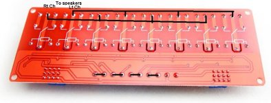
I'm not sure where to post this as I think it's one of a kind. Let me know or move it where it should be posted.
I've searched for a while and could not find a selector that lets one set of speakers and one line level input source, (pre-amp...ect) be the source for, as this one was built, up to "4" two channel amplifiers. I built it so I could hear differences between two channel amplifiers that I've built without having to connect and disconnect them every time. It's straight forward and easy to build. I jump connections across the negative speaker terminals. I used the 5v selection from the line level control board to feed and control the speaker board. Again I jumped the 5v input of the speaker board to select two at a time instead of one. Please Modify to your liking.
Hear is a list of materials.
Scott
Other items are stand-offs, screws...ect.


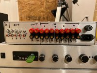
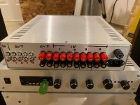
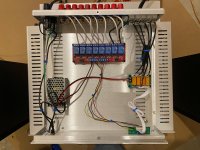
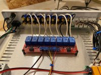
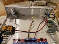
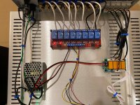
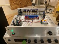


I've searched for a while and could not find a selector that lets one set of speakers and one line level input source, (pre-amp...ect) be the source for, as this one was built, up to "4" two channel amplifiers. I built it so I could hear differences between two channel amplifiers that I've built without having to connect and disconnect them every time. It's straight forward and easy to build. I jump connections across the negative speaker terminals. I used the 5v selection from the line level control board to feed and control the speaker board. Again I jumped the 5v input of the speaker board to select two at a time instead of one. Please Modify to your liking.
Hear is a list of materials.
Scott
HiLetgo 5V 8 Channel Relay Module with OPTO-Isolated Support High and Low Level Trigger
DIY Switching Board 4 Way Signal Selector Amplifier Relay Audio Input Switch Module
Banana Plugs for Speaker Wire (6 Pairs, 12 Pieces), 4mm Pin Plug Screw Type, 24K Gold Plated Connectors Insulated (Support 12 AWG to 20 AWG Wires) Two sets...
RCA M/M Stereo Audio Cable... As many as you need.
MEAN WELL RS-15-5 AC to DC Power Supply Single Output, 5V 3 Amp 15W
HiFi DIY Audio amp chassis / table top enclosure / Instrument Case 20-12123N from Pi Metal Products Inc.Other items are stand-offs, screws...ect.


Attachments
Last edited:
No need for relays. The simplest way is to get a 4 pole 2 trough switch and use each section for any of the stereo channels. If you have 5.1 units, you will need more switch sections.
A more beautifull selector may be using a pushbutton, a debouncing net, a counter (may be a 4017) and from its output a MOSFET 2N7000 driving the relays for each speaker. Also you can add a led or a digit via a 4511 to read directly the number of amplifier in use. The #4° output may reset the 4016 to return output #0.
A more beautifull selector may be using a pushbutton, a debouncing net, a counter (may be a 4017) and from its output a MOSFET 2N7000 driving the relays for each speaker. Also you can add a led or a digit via a 4511 to read directly the number of amplifier in use. The #4° output may reset the 4016 to return output #0.
If one was produced and for sale, I would have purchased one. What you would build would be fantastic!!!No need for relays. The simplest way is to get a 4 pole 2 trough switch and use each section for any of the stereo channels. If you have 5.1 units, you will need more switch sections.
A more beautifull selector may be using a pushbutton, a debouncing net, a counter (may be a 4017) and from its output a MOSFET 2N7000 driving the relays for each speaker. Also you can add a led or a digit via a 4511 to read directly the number of amplifier in use. The #4° output may reset the 4016 to return output #0.
Can I double like it?I'm not sure where to post this as I think it's one of a kind. Let me know or move it where it should be posted.
I've searched for a while and could not find a selector that lets one set of speakers and one line level input source, (pre-amp...ect) be the source for, as this one was built, up to "4" two channel amplifiers. I built it so I could hear differences between two channel amplifiers that I've built without having to connect and disconnect them every time. It's straight forward and easy to build. I jump connections across the negative speaker terminals. I used the 5v selection from the line level control board to feed and control the speaker board. Again I jumped the 5v input of the speaker board to select two at a time instead of one. Please Modify to your liking.
Hear is a list of materials.
Scott
HiLetgo 5V 8 Channel Relay Module with OPTO-Isolated Support High and Low Level Trigger
DIY Switching Board 4 Way Signal Selector Amplifier Relay Audio Input Switch Module
Banana Plugs for Speaker Wire (6 Pairs, 12 Pieces), 4mm Pin Plug Screw Type, 24K Gold Plated Connectors Insulated (Support 12 AWG to 20 AWG Wires) Two sets...
RCA M/M Stereo Audio Cable... As many as you need.
MEAN WELL RS-15-5 AC to DC Power Supply Single Output, 5V 3 Amp 15W
HiFi DIY Audio amp chassis / table top enclosure / Instrument Case 20-12123N from Pi Metal Products Inc.
Other items are stand-offs, screws...ect.
View attachment 1114048View attachment 1114048View attachment 1114050View attachment 1114051View attachment 1114052View attachment 1114053View attachment 1114054View attachment 1114056View attachment 1114055View attachment 1114054View attachment 1114053
View attachment 1114048
Actual building beats talking 100:1 👍 👍 👍
I suggest to add a 470R to 1K resistor on each input. If one or more of the amps is capacitively coupled to the load, you will ear a loud POP when switching this kind of amp into the speaker as the cap is charged to its steady voltage.
Also some vintage design with discrete transistors take the bootstrap voltage diverting the class A driver current directly across the voice coil. This kind of amps dislikes being without load because no proper bias on the output transistor is established. That's an example.
Also some vintage design with discrete transistors take the bootstrap voltage diverting the class A driver current directly across the voice coil. This kind of amps dislikes being without load because no proper bias on the output transistor is established. That's an example.
Attachments
Last edited:
I jump connections across the negative speaker terminals.
IMO, it's better to switch both positive and negative speaker terminals. Some amplifier (i.e. BTL) will not work or can be damaged if both left and right negative speaker terminals are connected together.
My suggestion is add another 8 channel relay module for negative speaker terminals switching.
I did something similar, but using larger relays... 6 amplifiers and 4 sets of speakers. Nixies for indication. 12V instead of 5V, and both negative and positive switched. I connect all nine of my amplifiers' inputs in parallel instead of switching the source from one amp to the next.
https://www.diyaudio.com/community/threads/tube-amp-with-no-spk-load.392468/post-7181669
https://www.diyaudio.com/community/threads/tube-amp-with-no-spk-load.392468/post-7181669
Good point! Did not think of that! I'm going to use double pole double throw 5vdc relay's on a separate board and feed them from this board. Of course I will remove the original relays from the circuit. Thanks for that.IMO, it's better to switch both positive and negative speaker terminals. Some amplifier (i.e. BTL) will not work or can be damaged if both left and right negative speaker terminals are connected together.
My suggestion is add another 8 channel relay module for negative speaker terminals switching.
I ended up getting one more relay board, they are inexpensive so what the heck. I'll just stack it on top of the other with standoffs. Thanks for the info about separating the Neg side. Will post picks when finished.Good point! Did not think of that! I'm going to use double pole double throw 5vdc relay's on a separate board and feed them from this board. Of course I will remove the original relays from the circuit. Thanks for that.
- Home
- Amplifiers
- Solid State
- Amplifier selector


