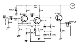
I'm curious about this phono preamp design, and wonder if anyone can do a 'spice' investigation of its design.
Namely to find out it's accuracy (%) at adhering to the standard RIAA curve.
And what a common 3.5mV cartridge would be amplifed to a final level after the Emitter follower 'booster' transistor.

Namely to find out it's accuracy (%) at adhering to the standard RIAA curve.
And what a common 3.5mV cartridge would be amplifed to a final level after the Emitter follower 'booster' transistor.
Attachments
Last edited:
Not to offend you, and sorry to ask, but why don't you do the LTspice yourself? .... the Y in DIY ")
LTSpice is not that hard to use and you'll learn a lot about the circuit.
Seems like a bit old and rudimentary circuit for a new build .... the effort will be the same, as going for something more "modern"
LTSpice is not that hard to use and you'll learn a lot about the circuit.
Seems like a bit old and rudimentary circuit for a new build .... the effort will be the same, as going for something more "modern"
Not to offend you either..... but referring to your nick and posts elsewhere,I'm curious about this phono preamp design, and wonder if anyone can do a 'spice' investigation of its design.
Namely to find out it's accuracy (%) at adhering to the standard RIAA curve.
And what a common 3.5mV cartridge would be amplifed to a final level after the cathode follower 'booster' transistor.
View attachment 1164975
you should know the name "emitter follower" (unless, it was a joke)
When I was in the computer industry, there was some on-stick regulator circuit for the memory. It had been used for so long and was so widespread, there wasnt a designer anywhere who wasnt afraid to touch it. As in "Let's do this instead"...Perfect example of "If it works, don´t fix it".
Yes.Not to offend you either..... but referring to your nick and posts elsewhere,
you should know the name "emitter follower" (unless, it was a joke)
I mistakenly used the wrong term, thanks for pointing that out.
However, as a human, I do make an occasional mistake.
LTSpice is not that hard to use and you'll learn a lot about the circuit.
I think that's a great idea tbh. You really would learn a lot. I desperately wanted to learn how to simulate circuits years ago and it was all thanks to Bob Cordell's book that I was able to find a way into LTspice. Before that I was staring at the workspace and wondering what the heck you needed to do.
I've simulated your preamp
but lets leave it for you to run it and see what it looks like.Here is the file. All you do is click the file and it will open all ready to run.
Click my signature line to see how to install LTspice and here is the link for LTspice. The thread details a lot about where LT installs stuff. To use it just install and click and run using the defaults:
https://www.analog.com/en/design-center/design-tools-and-calculators/ltspice-simulator.html
Here is the preamp file attached below...
Attachments
Sure, fully agree, and maybe you could take the circuit to even better performance with slightly better smd components and a few improvements to the circuit@Baldin...... right, but if your aim is to make a $20 riaa just for the fun of it, it´s quite OK.
Remember Bang & Olufsen?? They got away with using the same 2-transistor riaa in all their products......... for decades
Perfect example of "If it works, don´t fix it".
... but then we are into spending some engineering time Then again ... just ran the sim ... 3. harmonic only 35 db down!
..... so I stick to my first comment
Thanks Mooly, But that program is confusing enough to me.I think that's a great idea tbh. You really would learn a lot. I desperately wanted to learn how to simulate circuits years ago and it was all thanks to Bob Cordell's book that I was able to find a way into LTspice. Before that I was staring at the workspace and wondering what the heck you needed to do.
I've simulated your preamp
Here is the file. All you do is click the file and it will open all ready to run.
Click my signature line to see how to install LTspice and here is the link for LTspice. The thread details a lot about where LT installs stuff. To use it just install and click and run using the defaults:
https://www.analog.com/en/design-center/design-tools-and-calculators/ltspice-simulator.html
Here is the preamp file attached below...
View attachment 1165008
I only wanted a bit of help from someone who could take a moment to run it though and give me an idea of how accurate this design is, and if I should or could make any tweaks to bring it within say, a 1% accuracy of RIAA.
This is already on a thru-hole board, and to my ears sounds fine when compared to other commercially built preamps.
BTW, the output cap you used is wrong - it's a 1uF, and loaded by a 47K resistor in the amp.
Well, that gives me some idea of its performance.Here is the frequency response plot. At 1 kHz the gain is 46.88 and there is a greater than 4dB rise at low frequencies which would aggravate rumble. It would take some adjustment of the feedback components to flatten the response.
View attachment 1165025
That 'crest' from 70-15 Hz is fixable?
Seems the rest of the response to 20K is pretty linear.
Many moons ago, somebody came to me with an "esoteric" ($$$) preamp and asked me if I could improve it.
The circuit is kind of like yours, typically late 60's early 70's, before we really figured out how these transistor thingies work. And the RIAA was way off, like yours.
I fixed the EQ to about 1dB or better, gave it back to the guy. He came back later and said the sound was "woody" (his word) and he didn't like it a bit.
I think this is a case where one flaw masks another, and removing one can reveal others, and make the whole thing worse.
The moral is: don't do it.
Thanx Bill. Ya, I was thinking it needs a RIAA source. Do we need to build it out with a typical cart impedance? Besides a simple 47K resistor? LOL, you know I don't care beans about vinyl, but the simulation is interesting.Here is the frequency response plot. At 1 kHz the gain is 46.88 and there is a greater than 4dB rise at low frequencies which would aggravate rumble. It would take some adjustment of the feedback components to flatten the response.
View attachment 1165025
That's how it was for meThanks Mooly, But that program is confusing enough to me.
Anyhow, if you ever want a play its there (and you can always ask here if you are stuck)Adding an inverse RIAA at the output could be interesting as a check on accuracy.
- Home
- Source & Line
- Analogue Source
- An RIAA phono preamp