Hi guys,
i bought old Adcom GFA 555 mkI.
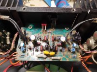
It must be cleaned, so i did, replaced electrolytics on PCB.
With service manual bias is set to 16-18mA.
But on left channel i have full DC +76V.
I measured with RLC meter all transistors of amplifier and i didnt find faulty one. I pulled out and measure one by one.
Right channel is working fine.
I could measure and compare channels.
Could anyone give me some help tips?
i bought old Adcom GFA 555 mkI.
It must be cleaned, so i did, replaced electrolytics on PCB.
With service manual bias is set to 16-18mA.
But on left channel i have full DC +76V.
I measured with RLC meter all transistors of amplifier and i didnt find faulty one. I pulled out and measure one by one.
Right channel is working fine.
I could measure and compare channels.
Could anyone give me some help tips?
Attachments
more info
Hi guys,
i bought old Adcom GFA 555 mkI.
It must be cleaned, so i did, replaced electrolytics on PCB.
With service manual bias is set to 16-18mA.
But on left channel i have full DC +76V.
I measured with RLC meter all transistors of amplifier and i didnt find faulty one. I pulled out and measure one by one.
Right channel is working fine.
I could measure and compare channels.
Could anyone give me some help tips?
Attachments

I am no engineer someone can correct me if I am wrong but 74v bias on Q621/623 base seems very high- looking at TP near R633 I would expect ~1v. Luckily diodes D611/613 may have saved the precious outputs but if I am correct Q621/623 probably shorted open. Compare against working channel please to confirm.
Since there maybe a short, it may be wise to build and power up the unit next time on a dim bulb tester. Also check if correct fuse is installed.
Since there maybe a short, it may be wise to build and power up the unit next time on a dim bulb tester. Also check if correct fuse is installed.
I am no engineer someone can correct me if I am wrong but 74v bias on Q621/623 base seems very high- looking at TP near R633 I would expect ~1v. Luckily diodes D611/613 may have saved the precious outputs but if I am correct Q621/623 probably shorted open. Compare against working channel please to confirm.
Since there maybe a short, it may be wise to build and power up the unit next time on a dim bulb tester. Also check if correct fuse is installed.
Hi,
thank you for reply 🙂
i compare Q621/623 to working R channel it looks identical.
I used ohm meter and it is almost identical readings. No shorts to ground.
Checking also diodes D611/613 on both channel identical.
All fuses are 5A/250V. Only one fuse is filled with sand on non-working L channel.
Any idea more?
More novice advice 🙂
-Examine for broken solder joints in problem channel, reflowing isnt a bad idea.
-Test for action on the bias control adjusting variable resistor, or pull and check resistance.
-Check test points provided in service manual around diff. inputs 601/603.
I am from reading this long 555 thread stating that the early units were shipped with lower rated driver transistors that are a weak link and there is a factory authorized upgraded driver.
Am i reading the same schematic as you?
http://www.civilwarmedicalbooks.com/bias/hfe_adcom_gfa-555_schematics.pdf
I see 6A fuses for F601-604. Are fuses suppose to be filled with sand? haha
More novice advice 🙂
-Examine for broken solder joints in problem channel, reflowing isnt a bad idea.
-Test for action on the bias control adjusting variable resistor, or pull and check resistance.
-Check test points provided in service manual around diff. inputs 601/603.
I am from reading this long 555 thread stating that the early units were shipped with lower rated driver transistors that are a weak link and there is a factory authorized upgraded driver.
Am i reading the same schematic as you?
http://www.civilwarmedicalbooks.com/bias/hfe_adcom_gfa-555_schematics.pdf
I see 6A fuses for F601-604. Are fuses suppose to be filled with sand? haha
Hi,
since i have very little time for repairing last months, i gave amplifier to experienced guy, who is repairing electronic stuff.
We will see what he will say.
Later i can upgrade with more realiable drivers. And as he suggested output protection for speakers also.