Hi all,
Another thread on this Vfet amp – this one was known to be deceased from when bought from E-bay. However, through a well-trodden tale of woe, I have a set of V-fets for it, just a case of figuring out what caused a problem in the first place,
First of all – service manual, I have refurbed a TA5650 previously and you can download plenty of V-fet information readily. You may have to have several goes before you find a really clear copy, but you are looking for the service manual and any bulletin you can find, either for the TA4650 or the TA5650.
Second of all it arrived! Since the seller gave no useful information on what or why it wasn’t working I figured check Vfets – heck I MIGHT be lucky
Yeah, I wasn’t 🙄
Not 100% sure that they, the V-Fets hadn’t been disturbed, for all I know at this point the amp was bought to salvage a set of transistors, as otherwise the internals are ( I’m 99% sure) completely un-touched and a reminder that more people smoked in the 80’s. Nothing burned and no obvious failures like a bulged cap or burnt resistor.
I'm intending to write this up as I go for information. This tale might not have a happy ending. But I have a dead 5650 and a dead 4650 to go at as well as what seems to be a set of V-fets
All the gear and no idea
Step 1 then: where does this fit on the Sony development cycle? These amps had at least one major update it seems, to try and reduce their propensity for self immolation. This example will need the fitted 1.5k, ¼ watt resistors R313, R314, R363 and R364 exchanging for 3.3k on the Power amp (F) board. DC bias was probably set at 75mv too but that’s irrelevant as it’ll be re-set later.
OK Party time at RS components, or your preferred parts peddler. £$£$£ add .gif of throwing cash...
I’ll take each board in turn at this stage, but my rules of engagement are:
Cap values – same, I believe the V-fet amps have to wake up in a certain ‘order’ from what I’ve read so I’m sticking with Sony’s values. Plus it’s nice to know that the character of the amp will be preserved. The only real gripe is that the power supply caps on the TA-4650 are 4700uF whereas on the substantially similar TA5640 they are a whopping 10,000uf. I had planned to split the difference with 6800uF but ultimately I bottled it – your first explicit invitation for “Comments Please”
Cap voltages – a variable; I figure that capacitor technology must have improved since this was built and I’m not trying to save every penny so if it fits and is a bigger voltage I’m ok with that – to a point eg a 10v cap might become a 25v cap of the same value.
Cap Types
Frankly, 0.47uf is not a value I associate with electrolytic capacitors and even 3.3uF is a push so these are going to be switched to polyester types. Same for C351 and C301 (10uF/16V) as they sit I the audio path. Equally, where available I prefer polymer types over electrolytic. That is MY preference your science may vary. Don't grumble, whatever, 40 year old etc...
Resistors
Just normal ¼ watt types nothing fancy, nothing fancy coming out nothing fancy going in. But they are checked if it says 3.3k it better measure that before soldering.
Final disclaimer, any specific components referenced are my choice, and probably based on the flimsiest of logic..
Sooooooo…..
Board 1 – power amp board (AKA the F board)
Pre-power on aims:
FIRST replace the so-called ‘death diodes’ VD1221 with 2x 1N4148 there are three on the Power amp board D414, D352 and D302. The latter are thermally mated to the transistors next to them, I’ve read both, that it’s worth doing, and it’s not worth doing. Sony did it, and it would have been another step in manufacturing; ergo, why not?
As a side note I’ve not yet come across a bust VD1221, maybe if they got this far they’re ok? I'm four amps in at this point
All Electrolytics will be replaced. Come on, this thing is more than 40 years old. Let’s just assume a component with a rated hours life time is past its best! (As I am slightly older than the amp, let’s also give thanks that this logic doesn’t extend any further, Oh hang on a minute…)
Not many capacitors really:
TA-4650 - F board
Qty old Value voltage New Value Voltage RS
C417 1 0.47uF 50v 0.47uF 63v 108-2429
C301. C351 2 10 uF 16v 4.7 uF 63v 171-9241
C306, C356 2 10 uF 16v 10 uF 25v 714-9622
C307, C357 2 10 uF 16v 10 uF 25v 714-9622
C303. C353 2 100 uF 10v 100 uF 16v 839-2341
C305, C355 2 220 uF 6.3v 220 uF 25v 839-2180
C418 1 10 uF 25v 10 uF 35v 839-2316
C420. C421 2 100 uF 50v 100 uF 100v 571-650
Cap count: 14
Note especially C301 and C351, are the electrolytics in the signal path!! So changing to ‘not that’ makes me feel better. The 4.7uf value doubles (?) the L.F. cut-off point but it seems that Sony buried it in the dirt to begin with, sub 1.5 Hz still feels OK, but we haven’t listened yet 😀
At this point there are no guarantees that this will actually work, come power up, but since these mods will happen anyway my logic is to simply remove variables before that point. Less likely a problem will be a bad cap if it’s a new cap!
Bias resistors RT301 and RT351 won’t have moved in years and again there’s [STILL] that smell of tobacco so I picture a thin film of Marlboro in the resistive layer – and goodbye. To be replaced with your favourite VR no doubt, but in this case I chose Bourns 2.2K multi turn trimmer 3296Y-1-222LF or RS no 785-9767.
Interestingly measured resistances on the old pots were close to mid-range (bagged and tagged for later examination if needed)
R423 which forms part of what appears to be a filter network has got hot at some point, at least enough to burn the markings. On removal it measured 1.4k rather than the 1k value it’s supposed to be. So I’ve swapped out for a ½ w 1k. Hopefully that was the right thing to do… Worryingly it’s a resistor that will see some pain if transistors fail on the input side
Pretty happy with the amp (F) board at this point, just a little nearer powering up.
To be continued....
Attachments

PT 2 followed very quickly
Power board…
On the TA4650 this is all one lump on top of the main power supply capacitors. The 5650 arrangement is much more elegant IMHO.
I must add as this board sits horizontally the GOOP that came off it after a good spray with isopropyl alcohol was spectacular #yellow
So "to remove, or not to remove". Aall of the following is possible without un-wire wrapping anything. Ultimately I chose to pull the board, as I felt I was doing more damage to the wiring through repeatedly moving it than was ideal.
Still amused by Sony’s decision to hard wire in the power bulb but NOT the power amplifier (to be clear, I wasn’t there and do actually respect the designers choices)
First real problem on this board – main PSU capacitors, I appreciate there is an argument that says leave well alone but in my experience removing OLD caps in this position makes and immediate audible impact. I’ve had some old gear where, although still functioning these capacitors actually rattled. So not even a debate here. The old Nichicon ones are out even though they measure good – sleep well my friends….
In any case, the old Nichicon (4700uf/50v) caps are an odd diameter and have an odd lead pitching, at least today - so that’s nice. I chose a near equivalent (if you squint a bit) Kemet 4700uf /63V (PEH200MA4470MU2). These are; #1 expensive, #2 Still expensive # 3 and don’t entirely fit…. So, again, “winning!” However, a 3D printed adaptor, and some massaging of the board later and we’re back in this century. Again if someone has input on increasing the capacitance here, I have at least one ear open. AFIK getting new caps in here is the most difficult part of the whole job so manage it as best you can, given local supply.
So re-capping (heh heh)
TA-4650 - G board
Qty Value voltage Value Voltage NEW RS
C401 1 4700 uf 50v 4700uf 189-765
C412 1 4700 uf 50v 4700uf 189-765
C413, C414, C415 3 47 uf 50v 47 uF 63v 739-5415
C403, C404, C406 3 47 uf 50v 47 uF 63v 739-5415
C407 1 3.3 uf 100v 3.3 uF 63v 185-4072
C409 1 100 uf 10v 100 uf 16v 839-2225
C405 1 100 uf 100v 100 uf 100v 839-4990
C402 1 100 uf 100v 100 uf 100v 839-4990
Cap count: 12
And then we need to deal with D403, or rather the lack of 403a. There is plenty of internet information about this but summarising diode 403 should be split in two and coupled to ground to prevent the voltages becoming offset. Even to my limited understanding of the circuit, this seems rational
Diodes around caps; there is at least one post “on the internet” suggesting that the charge pump capacitors should be reverse coupled to diodes, I don’t get this at all, seems that a direct short across a reverse biased electrolytic is worse than the original problem? Looking at you C403, C404 & C406. So, not happening here without further info. (again, comments please)
On the TA4650 the earth line runs under D403 so a simple clean and drill of that line gives the midpoint, so far so easy.
Diodes here are a 10E-2, Not available, thanks again to progress, so I took what can only be described as a parts bin decision – they were swapped for a Philips BYV95C, they had me at ‘fast soft-recovery’ <sigh>
Polymer caps for the 47uf at 50v and some chunky 100uf at 100V. As before capacitor technology has moved on and choice is limited for bigger diameters, I’m happy with the Wurth caps fitted, although I did buy ‘tall boy’ Panasonic FC’s before having second thoughts.
Lastly the VR for setting voltages - This time I've settled for a Bourns single turn pot - directly equivalent to the unit that came out (less nicotine) with accessibility once the amp is built
Again here we are at the end of this board
Attachments


Get the Dutch service update
Hi,
I have recently recommissioned a TA-5650. Best place to start is with the Dutch service update from Hifiengine ( under the TA-5650 page).
There were a number of component substitutions on the PA board, plus a lower bias setting (45mV vs 70mV). This was done to extend the life of the v-fets.
Reading your plan, it seems logical and replacing the suicide diodes is good security. I would also look at the PSU board mod to make it symmetrical, isa very easy fix.
Measure the main filter caps to see if they are still ok. Mine were fine. They are not directly replaceable as the terminal spacing and heights of substitutes are different.
Replace the output relay, this will be suspect by now.
Mine was also Nicotine stained and like yours, ran golden when sprayed with IPA..
I replaced the output terminals with 4mm binding posts.
I did manage to locate a couple of sets of V-FETs from around the globe (USA and AUS) but they are getting very difficult to find know good ones with the correct rankings (some of the Chinese ones may be real 18/60 but the rankings are unknown, so they just print kz-55 on them)
Clean the switches and pots, don’t use deoxit though, it gums them up.
They are great sounding amps, the Phono stage is supposed to be something special ( sk77). I am just listening to mine now.
What ranking are your v-fets? I know a couple of folk restoring 5650 and 8650 that may want to swap rankings to get correct ones ( matched per channel).
Oh, before you do power up, don’t put the vfets in, follow the service guides for power up, measure voltages, adjust, re-set bias for max g-s before installing vfets. Use Dim-Bulb but NOT a variac.
Let me know if you need help or service guides etc.
Good luck,
Jon
Last edited:
@Jonboylaw - Thanks for the info, I already changed the resistors per the Dutch service bulletin. S/N for the amp is 403612 and you can tell from the style of resistors it's fairly early
Today's job was the board with the output relay [RL901] (the E-Board) However, due to some bad internet advice or my plain lazyness in not thinking for myself. I ended up with a 24VAC relay In any case faced with this Sunday setback, I thought'd I'd have proper look at what I had. So relay out of the board and since I've now actually thoroughly examined the contacts on the newer relay - everything is almost as new I'm OK keeping it. This took FAR longer than replacing it so that's still best practice I'd think
In all this fun, I also discovered that the TA5650 has extra components here 😱 . Specifically filtering the output - C901 and C951 and associated resistors. So I've ended up taking the output board from a TA5650 and I'll use that, it's *far* cleaner, and the board is otherwise identical.
More photos attached.
Andy
Today's job was the board with the output relay [RL901] (the E-Board) However, due to some bad internet advice or my plain lazyness in not thinking for myself. I ended up with a 24VAC relay
In any case faced with this Sunday setback, I thought'd I'd have proper look at what I had. So relay out of the board and since I've now actually thoroughly examined the contacts on the newer relay - everything is almost as new I'm OK keeping it. This took FAR longer than replacing it so that's still best practice I'd thinkIn all this fun, I also discovered that the TA5650 has extra components here 😱 . Specifically filtering the output - C901 and C951 and associated resistors. So I've ended up taking the output board from a TA5650 and I'll use that, it's *far* cleaner, and the board is otherwise identical.
More photos attached.
Andy
Attachments


I replaced the output terminals with 4mm binding posts.
What posts did you use for the speakers, I'm having some difficulty finding some at the right price to quality ratio, having slightly fallen out with what I've used previously. But agree banana plugs are the way to go, those sprung connections are yucky
Also listening to my 5650 now, knowing full well I could have been even more thorough when I refurbished it, its being fed from an equally vintage Teac Z500, Good times. 😀
Andy
Hi Andy,
I had an input pannel from an old 70s Sony tuner that is the same size and lug spacing as the amp output boards. I removed the ancient RCAs and used some decent quality binding posts. You can use 2mm acrylic sheet and make your own easy enough.
Good news on the relay being good.
I noted on my output board, a couple of the resistors were a bit burnt.
How funny, I also have a z500, but in this case is a dual TDA1541A CD player. I assume yours is the cassette deck.
Btw, I have a spare 4650 PA board if yours is damaged. I did take the vfet sockets and thermistor, but the rest is original untouched.
Jon
Last edited:
Todays update
For anyone watching, this 'writing it up' business is definitely keeping me honest.
So volume board out, surprised to find that the wire wrapping just unpeeled, not surprised by MORE yellow goop
I do appreciate that the sensible thing here is to put it all back together and fix what's possibly bust. But it's too good an opportunity, while its looking like the worlds worst electronic postmortem, to delve further. As a result I find myself pouring over the schematics, and it looks like there are three electrolytics in the signal path on the Pre-amp side 😱 The horror 😀
Pic attached but:
A - Easy 'fix' I actually have some film caps of the same value. Probably will never use the Phono amp anyway so 'Meh'
B - OK always positively biased, AFAIK the 10k resistance of the pot means it Needs to be 10uF+, so I guess I'm stuck with a new polymer type at best?
C - Again if I've got it right the 100k resistance mans a 4.7uf film type can be substituted? Probably unnecessary as the caps always correctly biased but
Comments please 🙂 the fundamentals of Solid state amps are vague to me and I'll happily be put straight.
Andy
How funny, I also have a z500, but in this case is a dual TDA1541A CD player. I assume yours is the cassette deck.
Nope same dual DAC CD player, but that's a whole different tale, as that too had upgrades.
Mention a TDA1541a, and the world gets all weird quickly 😀 I may not have used the appropriate capacitors in the decoupling section and so on... Its very musical though

Best
Andy
Andy, no images on the post ..
Yeah, I also changed the decoupling caps on my z500 and like the look and weight, but am running an Arcam Alpha5 with home made 6n1P SRRP output stage grafted on with the op amps removed.
May tube the z500 for balanced out out as well, when time permits.
Yeah, I also changed the decoupling caps on my z500 and like the look and weight, but am running an Arcam Alpha5 with home made 6n1P SRRP output stage grafted on with the op amps removed.
May tube the z500 for balanced out out as well, when time permits.
@jonboylaw: If at first you don't succeed - perhaps skydiving is not the hobby for you.
So schematic attached
Does occur that there is a VERY esoteric 'tube' mod involving V-fets, might have to think about that one! Non-OS TDA1541a with V-fet output stage? Different day & different thread that one 😀
Cheers
Andy
So schematic attached
Does occur that there is a VERY esoteric 'tube' mod involving V-fets, might have to think about that one! Non-OS TDA1541a with V-fet output stage? Different day & different thread that one 😀
Cheers
Andy
Attachments

What's for dinner
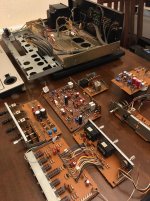
And so the trouble really starts here 😀
All boards cleaned - I moved to Q-tips and IPA - Isopropyl alcohol rather than the more enjoyable IPA sadly... Also contact cleanered any switch I could find🙂
SO where are we:
Still broken amp (more so actually ).
).
Caps changed as described.
Diodes modded as recommended - PSU and VD1221's
All boards should work (they won't) so now I'll put it all back together and see what the next problem is.
Andy
And so the trouble really starts here 😀
All boards cleaned - I moved to Q-tips and IPA - Isopropyl alcohol rather than the more enjoyable IPA sadly... Also contact cleanered any switch I could find🙂
SO where are we:
Still broken amp (more so actually
).Caps changed as described.
Diodes modded as recommended - PSU and VD1221's
All boards should work (they won't) so now I'll put it all back together and see what the next problem is.
Andy
Attachments

Top work on the output boards. They look super.
What is the problem with the amp boards. What symptoms. What is your test procedure.
What is the problem with the amp boards. What symptoms. What is your test procedure.
@jonboylaw - That's part 2 I guess,
To be clear, all I've done so far is replace old bits with new ones and clean a *ton* of grime.
Plan is to get it all back together and work through it (V-fets out first of course)
I suppose I should take the boring approach of fettling the pre-amp as job one, Even though the power amp is where the real interest is.
This amp was sold as broken so I'm not expecting an easy ride, maybe transistors, maybe nothing. We shall see.
It's one of the reasons I'm talking (mostly) to myself here. I really find it useful to document the process - makes me actually think about it, is that weird? 😕
Ah the joys of 40 yr old amps..
My 5650 was sold to me with an intermittent channel. I cleaned all the switched with servisol, did the diodes and mods and followed to bias procedure anit it has not missed a beat. If the vfets are ok, then it should be fixable.
I did change some of the input transistors to set the offset to below 10mV.
Think of it as a journey.
The tatty bits
OK so I don’t NEED to do any of this before we start but I’ve apparently been watching too much youtube to not launch into something spectacularly unnecessary before getting to the good stuff like powering it up
There’s more boards to clean and fettle.
This is mostly for my benefit as I’d like to hope DIYAudio isn’t going away so a good way of archiving what I did and sharing. So I’m going through this 'board by board' as a record for my own checking later…
The Power and Amp Boards are covered earlier but photo's!
Note the power height fix, the new Kemet caps were 5mm taller than previously. One M3 x 5mm stand off later and "tah-Dahhh". That worked very well. 😀
Andy
Attachments


A Board
A board - Phono Amp
The other V-Fet board, this was apparently so important it’s annotated as “A board”
(OK so given the vintage it’s fair that records were likely the only source beyond FM radio this amp might see but I’m not planning on getting a turntable)
On the TA4650 it shares real estate with the selector circuit – Which is actually more sensible in operation IMHO than the TA5650
There are just six Electrolytics to worry about
C101, C151 – 3.3uf / 25v replaced with 3.3uf/63v film
C107. C157 – 470uf/10v replaced with 470uf/25v
C103, C153 – 3.3uf /100v replaced with same
And this board needed a proper clean, all switches are open to one degree or another
Andy
Attachments


- Home
- Amplifiers
- Solid State
- Another Sony TA 4650 V-fet thread