Hello ! I have 2 Behringer amplifiers with below problems:
Behringer EP 4000 EUROPOWER - no.1 - premature clipping
It enters clipping too early (red LED clipping on), at around 15W, it starts to distort, if I reduce the potentiometer the red LED still stays on for a few seconds and still distorts - after a few seconds the red LED goes out and no more distortion , but only at low signal.
There is no DC on output and no idle current.
DIP_SWITCH does not change the premature clipping behavior.
Behringer EP 4000 EUROPOWER - no.2 - distortions
The left channel distorts strongly
Transistors checked as diodes = ok. Currently, some of the diodes checked = ok. I'll check the rest.
There is idle current - 0.5 A and DC on 3.5V output, without the possibility of adjustment from the 3 semi-adjustable.
If I turn on the load, the DC output drops to 0.05V and I have an audio signal on the X21 / pin 7.
No load, no audio signal on X21 / pin 7.
As you rotate the VR4 upward, the distortion disappears for a second as if the transient mode were to ensure proper polarization.
Attachments

C12 or C14 could be bad. They are not just bypass caps - but needed to boot strap the op amp supply with large signal swings. I’ve had several QSC amps that did this.
Failure mode #2 looks like it needs more digging.
Failure mode #2 looks like it needs more digging.
Regarding fault number one. I also recently had a QSC showing the same symptoms. I finally traced it to a high resistance pin on the socket for IC48, I think it was one of the supply pins.
That could be too - anything that reduces the op amp’s current capability. If it’s supply collapses, it can’t drive the MJE15030,15031 pair properly.
Each channel has its own independent power supply. It can’t be done from a common supply. The channels are likely labeled A and B, so they are not “volt” or “amp” labels - just to distinguish between channels.
Has anyone noticed that circuit diagram shows the main rails as 110A, 55A ?? erm...
It is normal for a class H amplifier.
It is abnormal that channel A has part of channel B on it's board (± 15V controller) and vice-versa, channel B has clipping for channel A on it's board. Difficult to isolate and work one them separately, to protect the working one, during powered tests.
If channel A fails, only channel B could work standalone. Not otherwise.
C12 or C14 could be bad. They are not just bypass caps - but needed to boot strap the op amp supply with large signal swings. I’ve had several QSC amps that did this.
Failure mode #2 looks like it needs more digging.
Yes, you have right, but I'm still checking channel A standalone - supposed could be a failuire on it that trigger earlier clipping.
C12 - C14 and all around clipping controller is on channel B board.
Step 2, as you said, is to make measurements on channel B - around IC4 and IC5.
In QSC-rmx_2450 (the genuine amplifier, Behringer it's a clone) service manual I've found some recommendations for earlier clipping on this model but it's strange that they omitted the outputs condition and 0.22 ohms resistors in troubleshooting scheme.
On the other hand, something is strange:
_No clipping if no load or high impedance load
_Clipping exists , no matter of DIP SW position
_clipping LED is triggered by IC4 outputs, IC4 outputs depends on (SPEAKER BUS - AFTER FUSE) -> R46-> pin 5 IC4 combined to pin 6 IC4 (gain output)
_clipping is controlled via R139->T34->IC5A but clipping no matter T34 emitter is grounded or not and the problem here is not the clipping is controlled (reducing gain) , but is "stated" / trigerred earlier
Question: Where is here - in this schematic - the comparision between output signal - positive or negative peak value reached by the monitored signal comparative to ± rails, to state a "clipping" situation ?
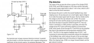

There is no “comparison” between input and output to detect clipping. It takes a volt or two from the op amp to get it to full output normally, which won’t turn on the “clip” LED or produce any voltage across R128. When the op amp’s output goes beyond that trying to drive T15 or T17 harder, the voltage across R128 rises indicating clipping. That activates the compressor circuit in the front end.
So, as I supposed, it is not a really clipping situation (some DC on output or high rail voltage on output etc) , seems to be a false clipping - and signal reduction is working as in real situation.
Clipping on 10W, not 1000W.
I'll do further checkings, It is still not clear to me that is a low (at clipping controller group level) or high voltage situation (at outputs level).
Maybe I will ground the base of T34 to isolate IC5 and see further. With all precautions, of course.
Thanks.
Clipping on 10W, not 1000W.
I'll do further checkings, It is still not clear to me that is a low (at clipping controller group level) or high voltage situation (at outputs level).
Maybe I will ground the base of T34 to isolate IC5 and see further. With all precautions, of course.
Thanks.
Working on it I've found all 8 emitter resistors burn. This is the reason only 10 W and clipping on output. I think this one it is a chinese Behringer, not an USA one. I'll revert with relevant pictures. A lot of difference between boards.
If all 8 emitter resistors are burnt out, are all the output transistors shorted?

Each channel has its own independent power supply. It can’t be done from a common supply. The channels are likely labeled A and B, so they are not “volt” or “amp” labels - just to distinguish between channels.
Yuk, I guess, but should be V+A, V++A, etc etc - names start with a letter, values with a digit, and 55A is 55 amps always, otherwise its just a shambles.
Thinking about it some more its clear the schematic was probable authored by non-English speaker, as the 0R22 reference
designator is incorrectly 0E22. Probably some other confusions in there too.
Last edited:
Question: Where is here - in this schematic - the comparision between output signal - positive or negative peak value reached by the monitored signal comparative to ± rails, to state a "clipping" situation ?
I think its just that when the feedback loop loses lock the LED conducts - in that situation the opamp can drive to its rails.
The emitter resistors may be just bad quality. I have seen this before.
Anyway, check the rails and transistors if possible. If there are rail fuses
insert resistors at first if you are not sure about the output devices. 10 ..
30 ohms will be fine and if they get hot during switch on you have some
additional problems.
Anyway, check the rails and transistors if possible. If there are rail fuses
insert resistors at first if you are not sure about the output devices. 10 ..
30 ohms will be fine and if they get hot during switch on you have some
additional problems.
If all 8 emitter resistors are burnt out, are all the output transistors shorted?
No, if outputs burnt - the speaker fuse should be burnt also due triac.
Fuse and outputs happily in good order. Pre-outputs and everything is on heater - ok Everything else also seems to be ok.
This is the main advantage on chinese clones - resistors are so bad that cease ahead of outputs 🙂.
It was a fortunate situation. Rare, also.
Tomorrow I'll buy new 0.22 ohms due I have none at 3W.
Still remain the crossover distorstion on Behringer no.2 - that gave me a lot of headache - due everythinng seems to be ok there, nothing burnt.
Attachments


Yuk, I guess, but should be V+A, V++A, etc etc - names start with a letter, values with a digit, and 55A is 55 amps always, otherwise its just a shambles.
Thinking about it some more its clear the schematic was probable authored by non-English speaker, as the 0R22 reference
designator is incorrectly 0E22. Probably some other confusions in there too.
It is 55 volts on A rail, not amps. It is H class amplifier, dual stage powered. 55V and if everything is ok and needed, 110V.
Schematics are genuine american beeing copied from QSC by Behringer.
The units itselves, not the diagrams, one is chinese - I suppose, one is american.
The emitter resistors may be just bad quality. I have seen this before.
Anyway, check the rails and transistors if possible. If there are rail fuses
insert resistors at first if you are not sure about the output devices. 10 ..
30 ohms will be fine and if they get hot during switch on you have some
additional problems.
I have already on my bench 2x220V lamps serial to 110V and 2x48V lamps serial to 55 V.
Never I connect directly during tests.
Sometimes using these lamps are not ok - I had several time situation that lamps obstructed the correct general voltage arrangement - but generally serve the purpose.
The emitter resistors may be just bad quality. I have seen this before.
Fusible resistors, intended to burn out when severely overloaded.
Its an old post but i’ll try my luck anyway.
My behringer ep 2000 has a short on all transistors on channel 2. Fuse on the rectifier burns instantly.
What can i start diagnosing? What would cause everything to be shorted?
Nothing unusual if i look at it, no burns or anything.
When you mention burned emitter resistors @wg_ski, would it be expected for everything to be shorted? Also how do i know if they are burned? They look fine in mine, and test the same as the working channel pcb.
Anyone have a clue?
Thanks
- Home
- Amplifiers
- Solid State
- Behringer EP 4000 EUROPOWER - clipping too early