This is new thread for Beta Nirvana derivative of Alpha Nirvana amp originally designed by Hugh Dean (AKSA).
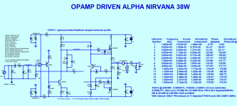
I was just playing with Alpha Nirvana schematic, and decided to try to use JFET op-amp as the input stage.
I actually have never seen class A amp driven by an op-amp, but here it is")
Cheap TL071 op-amp can be used here. This versions seems to be doing fine at 1kHz and 20kHz, and shows
much better sim results than discrete amp.
This is just a proof of concept. Speed, and stability have not been tested, but quick testing in spice so far looks promising.
Hugh, do you think this may work? Besides the fact that some "purists" may be put off by the op-amp...
The VAS transistor seems to be much more stable temperature-wise, than our previous attempt..
Edit: Actually I've seen class A amp driven by op-amp: Calor amp by Bora Jagodic.
Practical advantages of replacing LTP input stage with Jfet op-amp is that we are getting matched and thermally coupled Jfet LTP practically for free.
Any op-amp's input LTP (even in the cheapest op-amps) will be of better quality than discrete LTP.
TL071 op-amp was $1 (at Digikey) last time I ordered it, and there is nothing to adjust/measure (no trimmers).
DC output offset should be very close to zero without any extra effort.
Using op-amp allows for high gain loop, and more NFB, which leads to lower distortions.
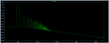
Values of (optional) R10/C6 allow to slightly modify shape of the FFT profile and harmonics behavior, feel free to experiment.
a) the latest schematics for 27V (Hugh) are in post #114
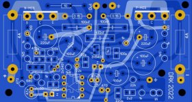
b) the latest PCB design is in post #57 and post #75
1st PCB is not very DIY friendly, it's dual layer, small (80mm x 43mm) and dense (used for my build)
2nd PCB is bigger, single layer, more DIY friendly version of the board.
As of 30 Mar 2022:
a) 'official' schematic of 27V rails version, blessed by Hugh (post #114):
- https://www.diyaudio.com/community/threads/beta-nirvana-class-a-new-amp.383431/post-6960222
b) two amps have been built:
- mell0wman (27V rails) - https://www.diyaudio.com/community/threads/beta-nirvana-class-a-new-amp.383431/post-6973593
- minek123 (20V rails) - https://www.diyaudio.com/community/threads/beta-nirvana-class-a-new-amp.383431/post-6980352
and https://www.diyaudio.com/community/threads/beta-nirvana-class-a-new-amp.383431/post-6984242
c) mell0wman designed his own PCB, see post #137
20V rails version:
Phase Margin: 88 degrees
Gain Margin: 24 dB
Thd at 1kHz (full power): 0.00035 %
Thd at 20kHz (full power): 0.0869 %
Idle current: 2.36A
Dissipation per Mosfet: 46W
DC offset: not higher than 8mV
27V rails version:
Phase Margin: 88 degrees
Gain Margin: 24 dB
Thd at 1kHz (full power): 0.00892 %
Thd at 20kHz (full power): 0.0540 %
Idle current: 1.7A
Dissipation per Mosfet: 45W
DC offset: not higher than 10mV
I was just playing with Alpha Nirvana schematic, and decided to try to use JFET op-amp as the input stage.
I actually have never seen class A amp driven by an op-amp, but here it is
Cheap TL071 op-amp can be used here. This versions seems to be doing fine at 1kHz and 20kHz, and shows
much better sim results than discrete amp.
This is just a proof of concept. Speed, and stability have not been tested, but quick testing in spice so far looks promising.
Hugh, do you think this may work? Besides the fact that some "purists" may be put off by the op-amp...
The VAS transistor seems to be much more stable temperature-wise, than our previous attempt..
Edit: Actually I've seen class A amp driven by op-amp: Calor amp by Bora Jagodic.
Practical advantages of replacing LTP input stage with Jfet op-amp is that we are getting matched and thermally coupled Jfet LTP practically for free.
Any op-amp's input LTP (even in the cheapest op-amps) will be of better quality than discrete LTP.
TL071 op-amp was $1 (at Digikey) last time I ordered it, and there is nothing to adjust/measure (no trimmers).
DC output offset should be very close to zero without any extra effort.
Using op-amp allows for high gain loop, and more NFB, which leads to lower distortions.
Values of (optional) R10/C6 allow to slightly modify shape of the FFT profile and harmonics behavior, feel free to experiment.
a) the latest schematics for 27V (Hugh) are in post #114
b) the latest PCB design is in post #57 and post #75
1st PCB is not very DIY friendly, it's dual layer, small (80mm x 43mm) and dense (used for my build)
2nd PCB is bigger, single layer, more DIY friendly version of the board.
As of 30 Mar 2022:
a) 'official' schematic of 27V rails version, blessed by Hugh (post #114):
- https://www.diyaudio.com/community/threads/beta-nirvana-class-a-new-amp.383431/post-6960222
b) two amps have been built:
- mell0wman (27V rails) - https://www.diyaudio.com/community/threads/beta-nirvana-class-a-new-amp.383431/post-6973593
- minek123 (20V rails) - https://www.diyaudio.com/community/threads/beta-nirvana-class-a-new-amp.383431/post-6980352
and https://www.diyaudio.com/community/threads/beta-nirvana-class-a-new-amp.383431/post-6984242
c) mell0wman designed his own PCB, see post #137
20V rails version:
Phase Margin: 88 degrees
Gain Margin: 24 dB
Thd at 1kHz (full power): 0.00035 %
Thd at 20kHz (full power): 0.0869 %
Idle current: 2.36A
Dissipation per Mosfet: 46W
DC offset: not higher than 8mV
27V rails version:
Phase Margin: 88 degrees
Gain Margin: 24 dB
Thd at 1kHz (full power): 0.00892 %
Thd at 20kHz (full power): 0.0540 %
Idle current: 1.7A
Dissipation per Mosfet: 45W
DC offset: not higher than 10mV
Attachments
-
 olg_simple_method.png30.9 KB · Views: 524
 -
 fft2_2.png8.4 KB · Views: 281
 -
 thd_follower1.png13.7 KB · Views: 645
 -
 beta_nirvana.20v.mcd.04Mar2022.png27.3 KB · Views: 428
 -
beta_nirvana.20v.mcd.04Mar2022.asc10.6 KB · Views: 75
-
 hugh_beta_nirvana_29march2022.png44.1 KB · Views: 424
 -
beta_nirvana.27v.mcd.05Mar2022.asc10.3 KB · Views: 68
Last edited:
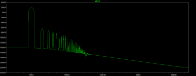
Here is slightly different harmonics profile with R6=150k (instead of original 200k).
We're working on it. The numbers are OK, but there is room for improvement. Need to sim the old AN and compare them.
Also Hugh is spending time improving this thing.
Overall parameters won't change much. I experimented with plethora of different op-amps when building other amps (E.g. in Unusual Amp thread),
and different amps may required slightly different values for compensation networks. Faster op-amps are more difficult to make amp stable.
So generally speaking, don't expect easy swap, without tweaking some RC values.
See this example from one of the previous amps..
Now, AN topology in general does not produce very fast amp (as far as slew rate is concerned), so using the fastest op-amps is rather counter productive here, especially since op-amp does not act as VAS here. Good old TL071 will do just fine.
Yes, this is good mod that we should do.
I'm also thinking of getting rid of source resistors, and moving current sensing/limiting (Q4) to the drain of the upper Fet.
This should solve Rallyfinnen issue, and lower Thd and output impedance further. Single pair of HexFets does not really need source resistors; they are needed here only as current sensors.
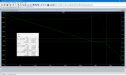
Could you post some loop gain plots? I'm guessing it's pretty high? See any issues stabilizing it?
We're working on it. The numbers are OK, but there is room for improvement. Need to sim the old AN and compare them.
Also Hugh is spending time improving this thing.
I'm guessing it could differ a lot depending on the op-amp, so swapping op-amps could be tricky?
Overall parameters won't change much. I experimented with plethora of different op-amps when building other amps (E.g. in Unusual Amp thread),
and different amps may required slightly different values for compensation networks. Faster op-amps are more difficult to make amp stable.
So generally speaking, don't expect easy swap, without tweaking some RC values.
See this example from one of the previous amps..
Now, AN topology in general does not produce very fast amp (as far as slew rate is concerned), so using the fastest op-amps is rather counter productive here, especially since op-amp does not act as VAS here. Good old TL071 will do just fine.
One thing you could do if you design a new PCB is to make an option to connect C7 to M1 drain?
I think that was an improvement on my AN, so maybe you want to try it? (lower output impedance)
Rallyfinnen makes a good point on the take up point of the bootstrap cap. He found much better bass with the cap taken to the source of the nmos.
Yes, this is good mod that we should do.
I'm also thinking of getting rid of source resistors, and moving current sensing/limiting (Q4) to the drain of the upper Fet.
This should solve Rallyfinnen issue, and lower Thd and output impedance further. Single pair of HexFets does not really need source resistors; they are needed here only as current sensors.
Attachments

Last edited:
I'll be designing my own PCB (and I'll publish it), but most likely it will be double sided.
I'm planing to re-use existing pre-drilled chassis from another amp, so the shape of my PCB (it's going to be small) might not be optimal for other builders...
I have a PCB prototype, but it is as described above. Not backward compatible with AN PCB, and not single sided.
Based on my original PCB for AN.
Once we have final version of the schematic ready, I'll publish it.
If there is enough interest, we can design backward compatible PCB later on.
Attachments
https://www.diyaudio.com/community/attachments/alfa-4r-37w-v2-jpg.987110/Good results. However, to be sure it's 'better' you must build both versions, standard your enhanced version, and then carefully audition it.
It is not sufficient to produce simulations to assess an amp; there is the psychoacoustic aspect, and you MUST audition it.
Good techniques to reduce distortion, looks good, but BUILD IT rather than proclaiming it superior to the original. Then tell the forum how it compares!
HD
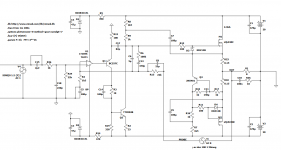
Hi guys. With this scheme, the parameters are better.
Attachments
Hi guys. With this scheme, the parameters are better.
Will try to sim your asc file.
There is many ways of making it better. My approach was to replace all these transistors you added in the front end, with an op-amp.
And since I've built original AN, I'll definitely try to compare new one with old one
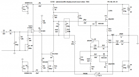
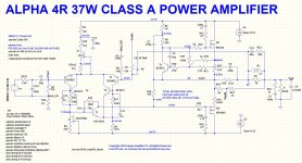
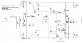
Here is next iteration of the Beta Nirvana.
Slightly different arrangement of the op-amp output. a follower used instead of cascode.
Much better results, including Thd, Phase and Gain margins.
This version is stable enough to warrant a prototype..
Phase Margin: 49 degrees, Gain Margin: 11 dB.
Thd within full power bandwidth: 0.006%
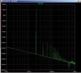
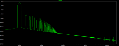
Two different FFT profiles shown, one with R6=100k and one with R6=150k.
Slightly different arrangement of the op-amp output. a follower used instead of cascode.
Much better results, including Thd, Phase and Gain margins.
This version is stable enough to warrant a prototype..
Phase Margin: 49 degrees, Gain Margin: 11 dB.
Thd within full power bandwidth: 0.006%
Two different FFT profiles shown, one with R6=100k and one with R6=150k.
Attachments
For now I'm testing 20V rails, because that's how my build gonna be. Once 20V version is finalized, we can do 27V.Hi Minek,
I might have missed this tidbit of information, are you planning to run the +/-27v rails for 39W@8R of the current Alpha Nirvana? Or the 20v on your schematic?
The only changes should be idle current adjustment (and I would like to have a pot for it), and gain adjustement.
I'm also thinking about having a pot for R6, so we can adjust the "profile" on the run
The possibility to switch between class A and AB ?The only changes should be idle current adjustment (and I would like to have a pot for it), and gain adjustement.
I think I have almost 'final' version for the schematic. I was trying to optimize both: cascode and follower versions (from post #1 and #6).
Both ended up with similar results, but follower won (in my mind) having lower Thd, and all the other characteristics the same or very close to the other version.
The biggest change is the relocation of the RC profile shaping circuit (which is optional - only for hard core A class listeners ).
This move allows for better stability and improves the shape of gain plots. Also, surprisingly, square wave handling is better.
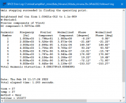
Simulated Thd numbers shown at full power. FFT "profile" remains the same as before.
Hugh, if you have some time, could you verify if this version is any good, and add your final touches ?
Once we have this schematic finalized, we can try to come up with 27V version (and 4 Ohm version?).
Edit: R5 should be of course the same as R14 (470 Ohm).
Both ended up with similar results, but follower won (in my mind) having lower Thd, and all the other characteristics the same or very close to the other version.
The biggest change is the relocation of the RC profile shaping circuit (which is optional - only for hard core A class listeners
).This move allows for better stability and improves the shape of gain plots. Also, surprisingly, square wave handling is better.
Simulated Thd numbers shown at full power. FFT "profile" remains the same as before.
Hugh, if you have some time, could you verify if this version is any good, and add your final touches ?
Once we have this schematic finalized, we can try to come up with 27V version (and 4 Ohm version?).
Edit: R5 should be of course the same as R14 (470 Ohm).
Attachments
Until recently in numerous previous versions the feedback loop was to the non-inverting op.amp input rather than the inverting input. I queried this in the thread from which this one is an offshoot and on that point a U-turn has been made. This is equally as important as the op.amp output connection and should not have been overlooked.Here is next iteration of the Beta Nirvana.
Slightly different arrangement of the op-amp output. a follower used instead of cascode.
Much better results, including Thd, Phase and Gain margins.
This version is stable enough to warrant a prototype..
Phase Margin: 49 degrees, Gain Margin: 11 dB.
Thd within full power bandwidth: 0.006%
Two different FFT profiles shown, one with R6=100k and one with R6=150k.
There is always a compromise between THD and stability, in my view it is better to err towards the latter and I think before building a prototype you would need to increase the simulated stability margins.
Completely agree.There is always a compromise between THD and stability, in my view it is better to err towards the latter
Until recently in numerous previous versions the feedback loop was to the non-inverting op.amp input rather than the inverting input.
If VAS is inverting, then op-amp should be inverting too.
If VAS is not inverting, then op-amp should be not inverting.
So if we change the type of VAS (as we did), from inverting to non-inverting (or vice-versa), op-amp arrangement of input and feedback points also has to change.
Both inputs of the op-amp are working the same way, except for inverting, and it should not make any difference in overall stability.
Agree with the invert/non-invert statements. Always best to have the opamp operating in non-inverting mode, for which it's designed......
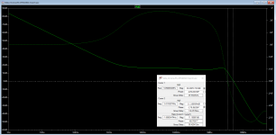
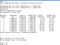
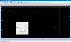
Not that impressed with the stability, Minek. Here are the figures from the Tian probe which reveal only 5dB GM and 34 degrees of PM.
This is not enough, though distortion and profile are excellent. But needs more reworking!
HD

Not that impressed with the stability, Minek. Here are the figures from the Tian probe which reveal only 5dB GM and 34 degrees of PM.
This is not enough, though distortion and profile are excellent. But needs more reworking!
HD
Hugh, wonder why your Tian probe results are so different than mine....
Shape is the same, just different levels.. I can't see the component values in your image (resolution is too low).
I know that in your schematics you are using different AC input level (I use 1.2V, and you 635mV ?), and, as a consequence different gain.
Also,I definitely see that feedback compensation is done differently - my schematic differs from yours.
Another difference - you have RL network at the output - before the probe is connected, this will also affect results.
I also see different values for bootsrap caps. Different compensation on the CCS - I'm using the original RC network from AN.
My guess is that you are also using different models, right?
Also, just noticed - you are using 27V rails.
So we are not comparing apples to apples. Not even close
My plot shows PM: 114 and GM: 9.
I guess I can try using Tian probe, but speaking historically, it was always pain in the neck...
Was never able to get results that were making any sense.
Last edited:
I have slightly changed the IC output circuit, so it takes power from the +15V rail and thereby uses a much larger emitter resistor. Current is unchanged at 3mA, so VAS is unchanged. C9 can be reduced ten times, and this profoundly changes the Bode plot and now GM is 25dB and PM 98 degrees. The 20KHz distortion is not as good (THD is 0.071%) but the profile is unchanged and H2 is easily dominant (-65dB, still much less than a SE tube at -45dB) so this should sound particularly sweet, with very punchy bass below 100Hz.
Minek, I work at a suggested 1 in the AC box for the Tian probe, and yes, my figures are different - one of us is wrong, for sure!
But I'm happy with this, I like your R10/C8 addition and suggest you publish!

Minek, I work at a suggested 1 in the AC box for the Tian probe, and yes, my figures are different - one of us is wrong, for sure!
But I'm happy with this, I like your R10/C8 addition and suggest you publish!
- Home
- Amplifiers
- Solid State
- Beta Nirvana Class A New Amp